

Page 1

®
®
®
®
®
TWO-SIDED GRILLS
MODEL
CG10IT4
GR10IT4
GR14ITTC-240
Installation and
Operation
Instructions
2M-Z7885 Rev. E 11/18/09
GR10IT4
1
Page 2

2
These symbols are intended to alert the user to the presence of
important operating and maintenance instructions in the manual
accompanying the appliance.
RETAIN THIS MANUAL FOR FUTURE REFERENCE
NOTICE
Using any part other than genuine Star factory supplied parts relieves the
manufacturer of all liability.
Star reserves the right to change specications and product design without
notice. Such revisions do not entitle the buyer to corresponding changes,
improvements, additions or replacements for previously purchased
equipment.
Due to periodic changes in designs, methods, procedures, policies and
regulations, the specications contained in this sheet are subject to change
without notice. While Star International Holdings Inc., Company exercises
good faith efforts to provide information that is accurate, we are not
responsible for errors or omissions in information provided or conclusions
reached as a result of using the specications. By using the information
provided, the user assumes all risks in connection with such use.
MAINTENANCE AND REPAIRS
Contact your local authorized service agent for service or required maintenance.
Please record the model number, serial number, voltage and purchase date in the area below and have it ready when
you call to ensure a faster service.
SAFETY SYMBOL
Model No.
Serial No.
Voltage
Purchase Date
Business 8:00 am to 4:30 p.m. Central Standard Time
Hours:
Telephone: (314) 678-6303
Fax: (314) 781-2714
E-mail Parts@star-mfg.com
Service@star-mfg.com
Warranty@star-mfg.com
Website: www.star-mfg.com
Service Help Desk
Authorized Service Agent Listing
Reference the listing provided with the unit
or
for an updated listing go to:
Website: www.star-mfg.com
E-mail Service@star-mfg.com
Mailing Address: Star International Holdings Inc., Company
10 Sunnen Drive
St. Louis, MO 63143
U.S.A
2
Page 3
ELECTRICAL SPECIFICATIONS
Model No. Volts Rated Wattage Amps NEMA Plug
CG10IT4-120V 120 1800 15.0 5-15P
CG10IT4-120C 120 1800 15.0 5-20P
GR10IT4-120V 120 1800 15.0 5-15P
GR10IT4-120C 120 1800 15.0 5-20P
GR14ITTC-240 240 3600 15.0 6-20P
120C = Canada
GENERAL INSTALLATION DATA
CAUTION
This equipment is designed and sold for commercial use only by personnel trained and
experienced in its operation and is not sold for consumer use in and around the home nor for
use directly by the general public in food service locations.
All shipping containers should be checked for freight damage both visible and concealed. This
unit has been tested and carefully packaged to insure delivery of your unit in perfect condition.
If equipment is received in damaged condition, either apparent or concealed, a claim must be
made with the delivering carrier.
Concealed damage or loss - if damage or loss is not apparent until after equipment is unpacked,
a request for inspection of concealed damage must be made with carrier within 15 days. Be
certain to retain all contents plus external and internal packaging materials for inspection. The
carrier will make an inspection and will supply necessary claim forms.
VENTILATION AND CLEARANCES
The installation of any components such as a vent hood, grease extractors, and/or re
extinguishing systems, must conform to their applicable nationally recognized installation
standards and/or local building codes.
ELECTRICAL CONNECTION
WARNING
Before making any electrical connection be sure to read the data plate located at the
bottom of the unit.
WARNING
CONNECT/PLUG UNIT INTO DEDICATED A.C. LINE ONLY SPECIFIED ON THE
DATA PLATE OF THE UNIT.
ELECTRICAL GROUNDING INSTRUCTIONS
WARNING
This unit is equipped with a 3-prong (grounding) plug for your protection against shock hazard
and must be plugged directly into a properly grounded 3-prong receptacle.
DO NOT CUT OR REMOVE THIS PLUG OR GROUNDING PRONG FROM THE
PLUG.
3
Page 4

INITIAL START UP
Level unit using the adjustable feet under the unit (approximately 1/2" adjustment).
Unpack the grill and put the owner's manual in a safe place for future reference. If rust is
visible on the grill, use a non-metallic scouring pad and scrub off the surface rust. Wipe down
the exterior and grilling area with a damp cloth. Take the grill to a ventilated area and turn
the thermostat to 8-9 to burn off the factory oil. The "burn off" is complete when the smoke is
gone (approximately 30 minutes). Brush any debris from the grill surfaces. Allow the grill to
cool and place it in its permanent position.
SEASONING THE COOKING SURFACES (Non-Chrome Only)
FIRST TIME SEASONING
Follow your company/corporate guidlines for seasoning cooking surfaces. or
1. Bring the grill to 300°F and leave it on while doing the next three steps.
2. Brush the cooking surfaces with a release agent. If using an aerosol agent,
rst apply into a cup and then brush onto cooking surface.
3. Let sit for 20 minutes, and then wipe clean using a warm damp cloth.
DAILY SEASONING
The grill should not require much seasoning while in use. In most cases, brush a light coating
of the baking release agent in the morning and occasionally throughtout the day will be enough
to prevent any sticking. It is not necessary to spray before grilling each item.
SETTING THE TEMPERATURE
The thermostat control knob is used to set the temperature to your requirements. The maximum
set point is 550°F (288°C), the minimum set point is 175°F (79°C).
Knob Position Approx. Temp
1-2 175°F / 79°C
3 200°F / 93°C
4 250°F / 121°C
5 300°F / 148°C
6 350°F / 176°C
7 400°F / 204°C
8 450°F / 232°C
9 500°F / 260°C
10 550°F / 287°C
PROGRAMMING THE TIMER
The timer may be factory pre-set. If changes are required follow these steps:
1. Press and hold the PGM button located on the left side of the display.
2. Press and hold one of the buttons (1 through 4) that needs to be programmed. After
approximately 1 second, the display window will show "_ _ _." When this is displayed, let
go of the buttons.
3. Enter the 3-digit security code. As the digits are entered, the corresponding horizontal bar
will move from the bottom to the center. The security code will not be displayed. Once
the correct security code is entered, the display will be the current time of the selected
button.
4. Change the time by pressing and holding the
button to increase the time or the button to decrease the time.
5. Once the correct time is displayed, press the PGM button to save the time.
6. One can now change the time by pressing another button and repeating steps 3 and 4.
7. When programming is complete, exit the programming mode by not pressing any buttons
for 15 seconds.
4
Page 5

ON/OFF/ON TOGGLE SWITCH (CG10IT & GR10IT ONLY)
The switch turns the unit on and off. The switch has three positions:
With the switch in this position, both top and bottom platens will heat.
With the switch in this position, neither platen will heat; the unit is OFF.
With the switch in this position only the bottom platen will heat.
DAILY OPERATION
Make sure the unit is plugged into the proper voltage and amp specied on the nameplate.
1. Turn the electrical power of the unit ON by placing the switch in either the up or down
position. IMPORTANT: The heat will not start until the thermostat is also turned to the
heating position, approximately 2 or higher on the dial.
2. To start heating, turn the temperature knob to the desired setting.
Initial start-up heating time is approximately 30 minutes.
3. Place product(s) on the bottom cooking surface.
4. Close the lid if the top if also ON. If the top is OFF, the unit can be operated similar to a
griddle.
5. Press the desired button (1 through 4) on the timer.
The timer countdown will begin regardless of what button is pressed.
6. When the countdown reaches 0:00, the display will ash and the unit will beep.
To turn off the beeping, press the same button (1 through 4) used to start the
countdown.
NOTE: If one wants to end a countdown, the same button (1 through 4) can be
pressed at any time in the countdown cycle. The display will return to the programmed
time for that button.
7. Raise the lid to the open position and remove the product(s).
8. For best performance, keep the lid closed when products are not being cooked.
OPERATING HINTS AND SAFETY
Disconnect power to the unit with the switch at the end of each day of operation. Do not leave
the unit in operation without an attendant.
Turn the thermostat down to 200°F (93°C) during idle periods. It will take only a few minutes
to regain operating temperature. Use a spatula to push excess grease into the grease drawer
after each load of food is cooked. This will reduce smoking of hot grease and carbonizing.
Do not leave the unit at high temperatures when not in use or during idle periods.
This will cause food particles and grease lm to carbonize.
"Season" cooking surfaces with non-salted vegetable oil to reduce product sticking.
MONTHLY LUBRICATION/INSPECTION
Apply two (2) drops of non-toxic mineral or vegetable oil to counter balance shoulder rivets
and plastic spacers.
Check and clean rollers to make sure they are rolling and not sliding on the cam surfaces of
the counterbalance. Check the bolts, screws and nuts; tighten if necessary.
5
Page 6

CLEANING
Begin cleaning procedure by using the operating procedures within your organization, or follow
the steps below:
1. If particles adhere to the cooking surface during the day, scrape them off with a spatula.
NOTE: It is best not to let food cook onto the grill, as food build-up on the grill will increase
sticking and smoking. In addition, carbon may build up on the grill surface and reduce the
cooking efciency.
CARBON BUILDUP:
is a combination of: releasing agents, oils, food particles etc. that has cooked itself to the
surface. After a period of time without cleaning, this will reduce performance and material
may start aking off. When that happens, follow the "Carbon Cleaning" procedures.
2. At the end of the day, wipe down all surfaces with a warm, damp cloth and mild detergent,
then dry.
A black matter that forms on or near the cooking surface. Generally this
CARBON CLEANING
When carbon build up occurs, use a carbon removal agent according to the instructions provided
with the cleaner. When this process is complete, you must re-season the grill according to your
company/corporate guidelines, or the seasoning instructions in this manual.
CAUTION
DO NOT IMMERSE OR LET THE UNIT STAND IN WATER.
DO NOT HOSE DOWN THE UNIT OR THE TABLE/COUNTER ON WHICH THE UNIT
IS LOCATED.
KEEP AWAY FROM RUNNING WATER.
CAUTION
DO NOT USE SHARP OBJECTS TO REMOVE CARBON BUILD-UP.
BEFORE CLEANING MAKE SURE POWER IS TURNED OFF, UNIT IS UNPLUGGED
AND IS NOT TOO HOT.
While holding top lid with one hand, apply only cleaners which are safe for aluminum and iron
surfaces. Wipe with clean sponge or towel until unit is clean.
CAUTION
DO NOT SPLASH FRONT CONTROL PANEL!
DO NOT SPLASH THE FLEX CONDUIT CONNECTING THE TOP AND BOTTOM
OF THE UNIT.
Remove and empty the grease catcher drawer, to clean using mild detergent and water.
CAUTION
Do not use ice or cold water to clean the cooking surfaces when the unit is hot.
The surfaces are cast aluminum or cast iron and may crack or deform under the
shock of rapid temperature change.
6
Page 7

OPERATION TROUBLESHOOTING
A. Unit is not heating.
1. Check if the unit is plugged into the correct receptacle.
2. Check the incoming power line.
3. Check that the switch is in the correct position.
4. Check that the thermostat is set to the proper temperature.
B. The top platen is not heating.
1. Check that the switch is in the correct position.
C. The counter balance roller is not rolling.
1. Clean the rollers.
If the unit still does not operate, contact the factory, one of its authorized representatives,
or a local service company for service or required maintenance.
7
Page 8

2M-4497-2 10/2010
The foregoing warranty is in lieu of any and all other warranties expressed or implied and constitutes the entire warranty.
FOR ASSISTANCE
Should you need any assistance regarding the Operation or Maintenance of any Star equipment; write, phone, fax or email our Service Department.
In all correspondence mention the Model number and the Serial number of your unit, and the voltage or type of gas you are using.
ALL:
* Pop-Up Toasters
* Butter Dispensers
* Pretzel Merchandisers
(Model 16PD-A Only)
* Pastry Display Cabinets
* Nacho Chip Merchandisers
* Accessories of any kind
* Sneeze Guards
* Pizza Ovens
(Model PO12 Only)
* Heat Lamps
* Pumps-Manual
Visit our Website at: www.star-mfg.com Email: service@star-mfg.com
THOROUGHLY INSPECT YOUR UNIT ON ARRIVAL
This unit has been tested for proper operation before leaving our plant to insure delivery of your unit in perfect condition. However, there are instances in
which the unit may be damaged in transit. In the event you discover any type of damage to your product upon receipt, you must immediately contact the
transportation company who delivered the item to you and initiate your claim with same. If this procedure is not followed, it may affect the warranty status of
the unit.
LIMITED EQUIPMENT WARRANTY
All workmanship and material in Star products have a one (1) year limited warranty on parts & labor in the United States and Canada. Such warranty is limited
to the original purchaser only and shall be effective from the date the equipment is placed in service. Star's obligation under this warranty is limited to the repair
of defects without charge, by the factory authorized service agency or one of its sub-agencies. Models that are considered portable (see below) should be taken
to the closest Star service agency, transportation prepaid.
> Star will not assume any responsibility for loss of revenue.
> On all shipments outside the United States and Canada, see International Warranty.
* The warranty period for the JetStar six (6) ounce & Super JetStar eight (8) ounce series popcorn machines is two (2) years.
* The warranty period for the Chrome-Max Griddles is ve (5) years on the griddle surface. See detailed warranty provided with unit.
* The warranty period for Teon/Dura-Tec coatings is one year under normal use and reasonable care. This warranty does not apply if damage occurs to
Teon/Dura-Tec coatings from improper cleaning, maintenance, use of metallic utensils, or abrasive cleaners, abrasive pads, product identiers and
point-of-sale attachments, or any other non-food object tha comes in continuous contact with the roller coating. This warranty does not apply to the
“non-stick” properties of such materials.
> This warranty does not apply to "Special Products" but to regular catalog items only. Star's warranty on "Special Products" is six (6) months on parts
and ninety (90) days on labor.
> This warranty does not apply to any item that is disassembled or tampered with for any purpose other than repair by a Star Authorized Service Center or
the Service Center's sub-agency.
> This warranty does not apply if damage occurs from improper installation, misuse, wrong voltage, wrong gas or operated contrary to the Installation and
Operating instructions.
> This warranty is not valid on Conveyor Ovens unless a "start-up/check-out" has been performed by a Factory Authorized Technician.
PARTS WARRANTY
Parts that are sold to repair out of warranty equipment are warranted for ninety (90) days. The part only is warranted. Labor to replace the part is chargeable to
the customer.
SERVICES NOT COVERED BY WARRANTY
PORTABLE EQUIPMENT
Star will not honor service bills that include travel time and mileage charges for servicing any products considered "Portable" including items listed below.
These products should be taken to the Service Agency for repair:
1. Travel time and mileage rendered beyond the 50 mile radius limit
2. Mileage and travel time on portable equipment (see below)
3. Labor to replace such items that can be replaced easily during a daily cleaning
routine, ie; removable kettles on fryers, knobs, grease drawers on griddles, etc.
4. Installation of equipment
5. Damages due to improper installation
6. Damages from abuse or misuse
7. Operated contrary to the Operating and Installation Instructions
8. Cleaning of equipment
9. Seasoning of griddle plates
10. Voltage conversions
11. Gas conversions
12. Pilot light adjustment
13. Miscellaneous adjustments
14. Thermostat calibration and by-pass adjustment
15. Resetting of circuit breakers or safety controls or reset buttons
16. Replacement of bulbs
17. Replacement of fuses
18. Repair of damage created during transit, delivery, &
installation OR created by acts of God
* The Model 510FD Fryer.
* The Model 526TOA Toaster Oven.
* The Model J4R, 4 oz. Popcorn Machine.
* The Model 518CMA & 526CMA Cheese Melter.
* The Model 12MC & 15MC & 18MCP Hot Food Merchandisers.
* The Model 12NCPW & 15NCPW Nacho Chip/Popcorn Warmer.
* All Hot Dog Equipment except Roller Grills & Drawer Bun Warmers.
* All Nacho Cheese Warmers except Model 11WLA Series Nacho Cheese Warmer.
* All Condiment Dispensers except the Model HPD & SPD Series Dispenser.
* All Specialty Food Warmers except Model 130R, 11RW Series, and 11WSA Series.
* All QCS/RCS Series Toasters except Model QCS3 & RCS3 Series.
* All Fast Steamer Models except Direct Connect Series.
8
Page 9
STAR MANUFACTURING INTERNATIONAL, INC.
MODEL: SEE ABOVE
SK2001 Rev. B 6/13/2005
CERTAIN INSTANCES MAY NOT BE AVAILABLE
ILLUSTRATIVE PURPOSES ONLY AND IN
SOME ITEMS ARE INCLUDED FOR
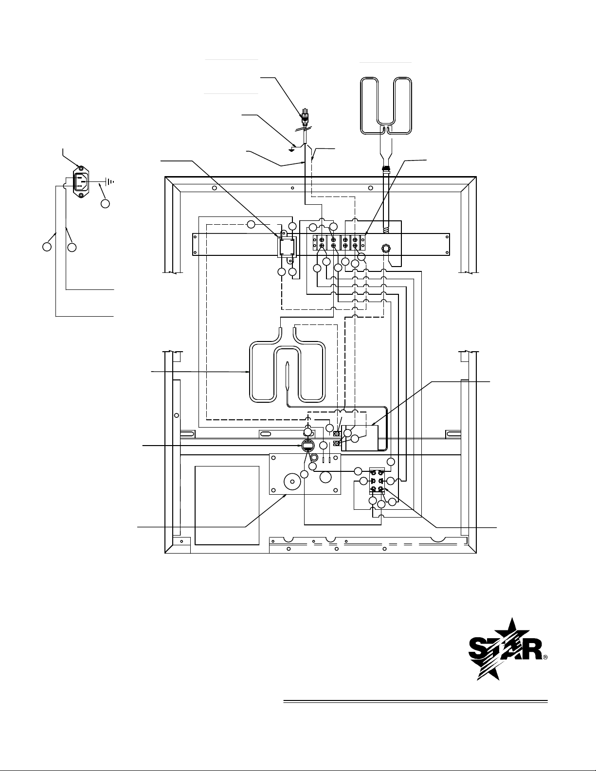
WIRE DIAGRAM, CG/GR, 10/14, 120V/230/240V, WITH TIMER
B
A
C
D
GREEN
BLACK
WHITE
15 AMP PLUG
NEMA 5-15P ON ALL STD 120V UNITS.
NEMA 5-20P ON ALL 120V CANADA UNITS.
NEMA 6-15P ON 240V, 1,800 WATT UNITS.
20 AMP PLUG
NEMA 6-20P ON 240V, 3,600 WATT UNITS.
TOP ELEMENT
TRANSFORMER
TERMINAL BLOCK
FOR REFERENCE
WIRING DIAGRAM IS SHOWN AS UNIT IS ASSEMBLED
WITH THE BOTTOM PLATE REMOVED. ITEMS ARE IN
GENERAL LOCATION BUT MAY BE RELOCATED OR SCALED
FOR CLARITY.
3
E2 E1
8
8
1
1
11
12
12
11
5
2
52
4
4
10
10
9
9
13
3
3
7
6
6
7
INDICATOR LIGHT
(POWER ON)
TIMER BOARD
SWITCH
THERMOSTAT
BOTTOM ELEMENT
230V UNITS
INLET IEC 320 16A
20
19
18
L
N
G
13
9
Page 10

10
Page 11

35
34
14
PELIGRO
SUPERIFICIE
FAVOR NO TOCAR
CALIENT
E
HOT SURFACE.
DONOT TOUCH
Donot hose down.
Keep away from
running water.
PRECAUCION
Maintengaselejos de
manguera.
No rocia con
corriente de ag
ua
.
o dejar que la base este
estancada sobre
agua
Favorde no s
umergir
DANGER
Do not immerseor let
CAUTION
base standinwater.
Keep away from
running
water.
DANGER
HOT SURFACE.
DONOT TO
UCH
PELIGRO
corriente de
agua.
SUPERIFICIE
FAVOR NO TOCAR
CALIENTE
PRECAUCION
Maintengasele
jos de
manguera.
No rocia con
o dejar que la base est
e
estanc
ada sobre agua
Favorde no s
umer
gir
Do not hose dow
n
.
Do no
t imm
erseor let
CAUTION
base s
tandinwate
r.
11
13
10
9
12
1
43
5
40
7
2
4
42
8
18
19
39
20
21
22
44
23
24
25
26
37
49
33
27
27
29
30
31
3
6
41
17
52
51
46
45
50
47
48
NAMEPLATE
STAR MANUFACTURING INTERNATIONAL, INC.
CERTAIN INSTANCES MAY NOT BE AVAILABLE
ILLUSTRATIVE PURPOSES ONLY AND IN
SOME ITEMS ARE INCLUDED FOR
MODEL: GR10IT4
SK2082 REV. A
No reproduction or disclosure of its
to Star Manufacturing International, Inc.
This drawing contains information confidential
contents is permitted.
52
11
Page 12

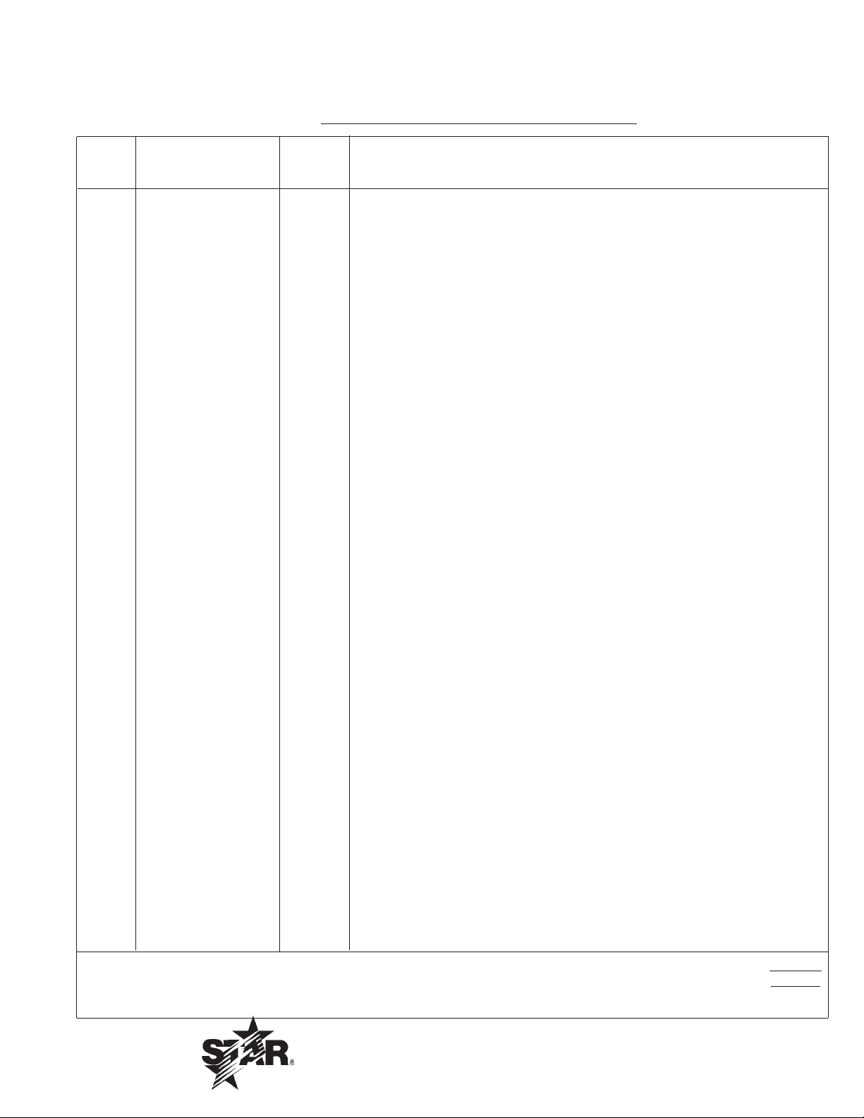
PARTS LIST November 18, 2009, Rev E
Star Two-Sided Grill
CG10IT4, GR10IT4-120V
MODEL
Key
Number
1 2M-Z7667 1 OVERLAY W/TIMER - 10"
2 2J-Z7668 1 TIMER CONTROL
3 2K-Z1971 4 SPACER
4 2E-Z6863 1 SWITCH - 3 POSITION
5 2R-Z4621 1 KNOB - CONTROL
6 2T-6447 1 THERMOSTAT 118V-236V
7 D9-GR0234 1 FACEPLATE ASSEMBLY - 10" WITH TIMER
8 D9-GR0062 1 BODY ASSEMBLY - 10"
9 D9-GR0034 1 GREASE CABINET ASSEMBLY
10 D9-GR0517 1 GREASE DRAWER ASSEMBLY
11 2A-Z11501 4 FOOT - 1" ADJUSTABLE
12 D9-Z2711 1 BASE BOTTOM - 10"
13 2E-Z2935 1 CORD, SJTO 14/3 NEMA 5-15P 120V
2E-Z4118 1 CORD, POWER 12/3 5-20P 120C
14 2K-Y3240 1 BUSHING HEYCO SR 17-2
17 2A-Z6484 2 PLATE - COUNTER BALANCE MOUNT
18 D9-GR0053 1 REAR LINER ASSEMBLY - 10" BOTTOM
19 2E-Z2894 1 TERMINAL BLOCK
20 2E-05-07-0351 1 TRANSFORMER 115/10V 6VA
21 2R-Z2907 1 COUNTER BALANCE - 10" IRON
22 D9-Z2774 1 BOTTOM INSULATION RETAINING PLATE - 10"
23 D9-Z2908 1 INSULATION - 10"
24 D9-Z2773 1 BOTTOM ELEMENT RETAINING PLATE - 10"
25 2N-Z1979 1 ELEMENT - HEATING 1000W/120V (BOTTOM)
26 PS-GR0360 1 KIT, 2F-Z1933 CASTING - SMOOTH BOTTOM - 10" IRON
PS-GR0358 1 KIT, 2F-Z1935 MACH-CAST GR BOTTOM 10" IRON (CG MODEL)
27 D9-Z2772 1 TOP ELEMENT - INSULATED PLATE - 10"
28 D9-GR0084 1 TOP RETAINING PLATE ASSEMBLY - 10"
29 B9-04-WB-0046 1 CLAMP WIRE SUPPORT
30 PS-Z1978 1 ELEMENT - HEATING 800W/120V (TOP)
31 PS-GR0349 1 KIT, 2F-Z1932 CASTING - SMOOTH TOP - 10" IRON
PS-GR0347 1 KIT, 2F-Z1934 MACHINE-CAST GR TOP-IRON 10" (CG MODEL)
33 2C-Z3200 2 PIN - TOP HOUSING
34 2B-Z2988 2 ARM - 10"
35 2V-Z2990 1 HANDLE - 10"
37 2M-Z2620 1 LABEL - CAUTION (BI-LINGUAL)
39 2V-Z3252 1 ROD - TOP HOUSING LATCH
40 2A-Z3026 1 HALF CLIP .437
41 D9-Z3071 4 BRACKET - HANDLE
42 2V-Z3072 2 HANDLE - SIDE
43 2I-05-07-0013 1 BOOT - SWITCH
44 2A-Z6604 8 SPACER - INSULATION PLATE
45 2I-Z3380 2 THERMOSTAT SEAL WASHER
46 2I-Z3379 1 GROMMET - THERMOSTAT
47 2C-Z2899 2 5/16-18 UNC LOCKNUT
48 1O-E1500 0.33 SLEEVING #4 .208ID GLASS
49 D9-GR0203 1 TOP HOUSING AND CONDUIT ASSEMBLY
50 2E-Z3768 1 LOCKNUT, CONDUIT, 1/2 INCH
51 2J-Y6689 1 PILOT LIGHT 120V
52 2C-08-07-0285 8 STUD, SELF TAPPING
Part
Number
Number
Per
Unit
Description
1
IMPORTANT: WHEN ORDERING, SPECIFY VOLTAGE OR TYPE GAS DESIRED PAGE
1
INCLUDE MODEL AND SERIAL NUMBER OF
Some items are included for illustrative purposes only and in certain instances may not be available.
Star Manufacturing International, Inc.
12
Page 13

STAR MANUFACTURING INTERNATIONAL, INC.
GR14,GR14I, GR14ITTC,CG14,CG14I,CG14IGT
SK1687 REV. E 6/22/09
TOP &
ON
POWER
TIME
START
STOP
35
22
23
38
12
31
50
16
51
52
53
2
3
7
6
11
27
26
25
24
FAVOR NO TO
CAR
PELIGRO
SUPERIFICIE
CALIENTE
CAUTION
running water.
Keep away from
Do not hose down.
base stand in water.
Do not immerse or
let
corriente de agua
.
No rocia con
manguera.
Maintengase
lejos
de
DO NOT TOUCH
DANGER
HOT SURFACE.
PRECAUCION
Favordeno sumergir
estancada sobreagua
o dejar quela base este
30
21
20
49
33
32
29
BOTTOM
OFF
BOTTOM
ON ( I )
POWER ON
PRO-MAX
14
15
16
18
19
17
17
46
58
59
56
57
This drawing contains information confidential
to Star Manufacturing International, Inc.
No reproduction or disclosure of its
CERTAIN INSTANCES MAY NOT BE AVAILABLE
ILLUSTRATIVE PURPOSES ONLY AND IN
SOME ITEMS ARE INCLUDED FOR
contents is permitted.
MODEL GR10I,CG10I,
8
19
4
5
1
28
13
10
34
39
40
41
42
45
44
47
54
55
37
48
9
54
Hinge Mech.
13
Page 14

PARTS LIST November 18, 2009, Rev E
Star Two-Sided Grill
GR14ITTC GRILL,SANDWICH,14"W/TIMER
MODEL
Key
Number
1 2C-Z2992 2 SCREW, HANDLE
2 2V-Z2989 1 HANDLE - 14”
3 2B-Z3336 2 ARM
4 2C-08-07-0040 4 NUT
4 2C-08-07-0262 4 WASHER
5 2C-Z2992 4 SCREW, ARM TO BRACKET
6 D9-Z2036 1 HOUSING-TOP-14”
7 2C-Z3200 2 PIN - TOP HOUSING
8 2C-08-07-0040 2 RETAINER RING
9 2C-Z2899 2 1/4” NUT, USE PART NUMBER 2C-Z2820
10 2A-Z3827 1 CONDUIT KEEPER PLATE
11 2C-Z3780 2 CONDUIT RETAINER
12 2E-Z2898 1 CONDUIT ASSY. - PTFE
13 2E-Z3768 1 CONDUIT LOCKNUT
14 D9-04-GR-0166 1 WIRE MOUNT
15 D9-GR0079 1 TOP RETAINING PLATE AY/14
16 D9-Z2888 2 INSULATION - 14”
17 2A-Z6604 8 SPACER - INSULATED PLATE
18 D9-Z2075 1 TOP ELEMENT/INS. PLATE/14
19 2C-08-07-0285 8 SCREW, ELEMENT RET. PLATE
20 PS-Z2391 1 TOP ELEMENT, HEATING, 1800W/240
21 PS-GR0352 1 CASTING, SM. TOP, IRON-14”
22 2K-Y6764 1 BUSHING
23 2E-Z2905 1 CORD SJTO 12/2 NEMA 6-20P
24 2M-Z2620 1 LABEL CAUTION, BI-LINGUAL
25 2E-05-07-0350 1 TRANSFORMER 230V/10V 6VA
26 2E-Z2894 1 TERMINAL BLOCK
27 D9-GR0080 1 REAR LINER ASSY. - 14”/REAR
28 2C-1512 2 SCREW - PIN ASSY
29 2V-Z3252 1 PIN ASSY - TOP HOUSING STOP
30 2R-Z2896 1 COUNTERBALANCE -14”-IRON
31 2A-Z6484 2 TORQUE BOX ASSY.
32 D9-Z3071 4 BRACKET-HANDLE
33 2V-Z3072 2 HANDLE - SIDE
34 D9-GR0150 1 GREASE CABINET ASSY.
35 D9-GR0518 1 GREASE DRAWER ASSY.
37 D9-Z3259 1 BASE BOTTOM - 14”
38 2A-Z11500 4 4" NON SKID FOOT BASE
39 D9-GR0184 1 BODY ASSY
40 2J-Z7668 1 TIMER CONTROL
41 2K-Z1971 4 SPACER
43 D9-GR0390 1 FACEPLATE ASSY. - 14” NO TIMER
44 2E-Z3808 1 SWITCH(EATON)-30A@120V,SPST
45 2M-Z11267 1 OVERLAY
46 2I-05-07-0013 1 RUBBER BOOT, SWITCH
47 2R-Z4621 1 KNOB-CONTROL
48 2T-6447 1 THERMOSTAT 118V-236V
49 2A-Z3026 1 HALF CLIP
50 D9-Z8082 1 BTM. INSULATION RET. PLT. 14”
51 D9-Z8082 1 BTM ELEMENT RET. PLATE 14”
52 2N-Z2392 1 BTM ELEMENT, HEATING, 1800W/240V
53 PS-Z1949 1 CASTING, SM. BOT., IRON-14”
54 2C-Z5883 8 SCREW 10-24X1/2 FZA
55 PS-GR134 2 ROLLER BEARING KIT
56 D9-Z11283 1 COUNTER BALANCE STOP,BASE
Part
Number
Number
Per
Unit
Description
1
IMPORTANT: WHEN ORDERING, SPECIFY VOLTAGE OR TYPE GAS DESIRED PAGE
2
INCLUDE MODEL AND SERIAL NUMBER OF
Some items are included for illustrative purposes only and in certain instances may not be available.
Star Manufacturing International, Inc.
14
Page 15
PARTS LIST November 18, 2009, Rev E
Star Two-Sided Grill
GR14ITTC GRILL,SANDWICH,14"W/TIMER
MODEL
Key
Number
57 D9-Z11284 1 COUNTER BALANCE STOP,BRKT
58 2M-12-07-0038 1 LABEL ON & OFF
59 Z1-70-07-0343 1 SWITCH GUARD
NI 2V-Z3027 2 CROSS SUPPORT (NOT SHOWN)
NI D9-Z9516 2 SIDE SUPPORT
Part
Number
Number
Per
Unit
Description
2
IMPORTANT: WHEN ORDERING, SPECIFY VOLTAGE OR TYPE GAS DESIRED PAGE
2
INCLUDE MODEL AND SERIAL NUMBER OF
Some items are included for illustrative purposes only and in certain instances may not be available.
Star Manufacturing International, Inc.
15
Page 16

STAR INTERNATIONAL HOLDINGS INC. COMPANY
Star - Holman - Lang - Wells - Bloomeld - Toastmaster
10 Sunnen Drive, St. Louis, MO 63143 U.S.A.
(314) 678-6303
www.star-mfg.com
 Loading...