

Page 1
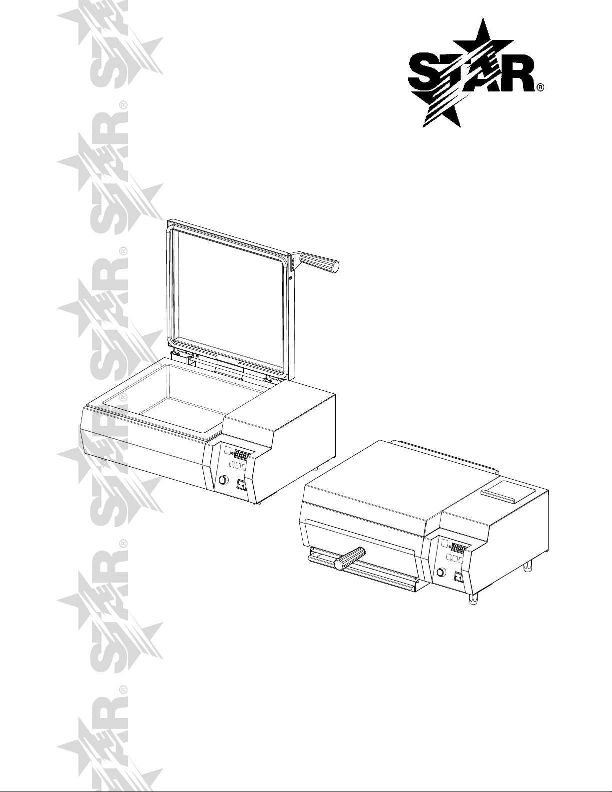
FAST
STEAMER
MODEL
FS1R, FS1D, FS1RT, FS1DT
FS2R, FS2D, FS2RT, FS2DT
FSFR, FSFD, FSFRT, FSFDT
Installation and
Operation
Instructions
2M-Z10887 Rev. E 10/24/2011
FS2DT
FSFRT
1
Page 2

SAFETY SYMBOL
Using any part other than genuine Star factory supplied parts relieves the
manufacturer of all liability.
Star reserves the right to change specications and product design without
notice. Such revisions do not entitle the buyer to corresponding changes,
improvements, additions or replacements for previously purchased
equipment.
Due to periodic changes in designs, methods, procedures, policies and
regulations, the specications contained in this sheet are subject to change
without notice. While Star International Holdings Inc., Company exercises
good faith efforts to provide information that is accurate, we are not
responsible for errors or omissions in information provided or conclusions
reached as a result of using the specications. By using the information
provided, the user assumes all risks in connection with such use.
These symbols are intended to alert the user to the presence of
important operating and maintenance instructions in the manual
accompanying the appliance.
RETAIN THIS MANUAL FOR FUTURE REFERENCE
NOTICE
MAINTENANCE AND REPAIRS
Contact your local authorized service agent for service or required maintenance.
Please record the model number, serial number, voltage and purchase date in the area below and have it ready when
you call to ensure a faster service.
Authorized Service Agent Listing
Model No.
Serial No.
Voltage
Purchase Date
Reference the listing provided with the unit
or
for an updated listing go to:
Website: www.star-mfg.com
E-mail Service@star-mfg.com
Service Help Desk
Business 8:00 am to 4:30 p.m. Central Standard Time
Hours:
Telephone: (314) 678-6303
Fax: (314) 781-2714
E-mail Parts@star-mfg.com
Service@star-mfg.com
Warranty@star-mfg.com
Website: www.star-mfg.com
Mailing Address: Star International Holdings Inc., Company
10 Sunnen Drive
St. Louis, MO 63143
U.S.A
2
2
2M-Z10887 Owners Manual Fast Steamers
Page 3
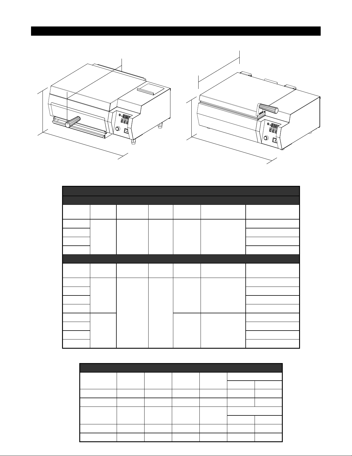
SPECIFICATIONS
C
C
B
A
B
IL1361
A
FRONT LOADING TOP LOADING
FAST STEAMERS SPECIFICATIONS
FRONT LOADING
Model No.
“A” Width
Inches/CM
FSFR
FSFD D
FSFRT R
23in. /
58.4cm
FSFDT D
Model No.
“A” Width
Inches/CM
FS1R
FS1D D
FS1RT R
18.8in /
47.8cm
FS1DT D
FS2R
FS2D D
FS2RT R
22.4in /
56.9cm
FS2DT D
“B” Height
Inches/CM
9.5in / 24.1c,
“B” Height
Inches/CM
10.5in /
26.7cm
“C” Depth
Inches/CM
Approx. Shp
21.5in /
54.4cm
TOP LOADING
“C” Depth
Inches/CM
Approx. Shp
17.2in /
43.7cm
Weight
48lbs /
21.8kg
Weight
48lbs /
21.8kg
58lbs /
26.4kg
Capacity (inches)
W_x_D_x_H
13.75” x 13.75” x 3”
Pan Size
1/2
2/3
Direct Connect (D)
Water Reservoir (R)
R
Direct Connect(D)
Water Reservoir (R)
R
R
2M-Z10887 Owners Manual Fast Steamers
Front Loading
Model No. Voltage Wattage Amps Nema Plug
FSF 208V 3,300 15.9 6-20P X X
FSF 240V 3,600 15 6-20P X X
Top Loading
Model No. Voltage Wattage Amps Nema Plug
FS1/FS2 120V 1,800 15 5-15P X -
FS1/FS2 120VC 1,800 15 5-20P X X
ELECTRICAL SPECIFICATIONS
Certication
UL CUL
Certication
UL CUL
3
Page 4

CAUTION
WARNING
GENERAL INFORMATION
This equipment is designed and sold for commercial use only by personnel trained and experienced
in its operation and is not sold for consumer use in and around the home nor for use directly by the
general public in food service locations.
Before using your new equipment read and understand all the instructions & labels associated with
the unit prior to putting it into operation. Make sure all people associated with its use understand the
units operation & safety before they use the unit.
All shipping containers should be checked for freight damage both visible and concealed. This
unit has been tested and carefully packaged to insure delivery of your unit in perfect condition. If
equipment is received in damaged condition, either apparent or concealed, a claim must be made
with the delivering carrier.
Concealed damage or loss - if damage or loss is not apparent until after equipment is unpacked, a
request for inspection of concealed damage must be made with carrier within 15 days. Be certain to
retain all contents plus external and internal packaging materials for inspection. The carrier will make
an inspection and will supply necessary claim forms.
These models are equipped for the voltage and wattage indicated on the nameplate. These units
are designed to operate on alternating current (A.C.), two wire single phase service only and are
equipped with an approved lead in cord set with a three prong grounding type plug.
DO NOT CONNECT TO DIRECT CURRENT (D.C.).
UNPACKING
Carefully remove the steamer from the shipping and packing & protective material. Remove all
removable parts and clean with hot water and mild detergent. Wipe the unit using damp cloth. Never
hose down the unit with water, this steamer has
Unit should also contain:
• Operations manual & Authorized Service Agent Listing Packet
• Inlet Hose Assembly (non-reservoir units only)
• Spatula tray (front loading units only)
Purchasers Responsibility
• To see that the electric & water services for the unit are installed on site in accordance with
the manufacturer's specications and municipal codes.
• A water pressure regulator must be used, failure to operate this unit without a regulator will
result in situations that will damage the unit.
2M-Z10887 Owners Manual Fast Steamers
4
Page 5

WARNING
CAUTION
INSTALLATION
ELECTRICAL CONNECTION
For your protection, we recommend that a qualied electrician install this appliance.
The electrician should be familiar with electrical installations and your local electrical requirements.
Proper connections and power supply are essential for efcient performance. The supply circuit should
be properly fused as required by local electrical code.
Before making any electrical connection be sure to read data plate which is located on the rear
of the unit.
Electrical Grounding Instructions
This unit is equipped with a 3-prong (grounded) plug for your protection against shock hazard and must
be plugged directly into a properly grounded 3-prong receptacle.
DO NOT CUT OR REMOVE THIS PLUG OR GROUNDED PRONG FROM THE
PLUG.
CONNECT/PLUG UNIT INTO DEDICATED A.C. LINE ONLY SPECIFIED ON THE
DATA PLATE OF THE UNIT.
PRESET TIME
If adjustments are required, please refer to the time programming section in this manual.
°F/°C CONVERSION
To change the temperature display from °F to °C or from °C to °F, hold the TEMP button while the
unit is turned off. While holding the TEMP button, turn the unit on. The display will be the changed
temperature mode. To change back, repeat the procedure.
2M-Z10887 Owners Manual Fast Steamers
5
Page 6
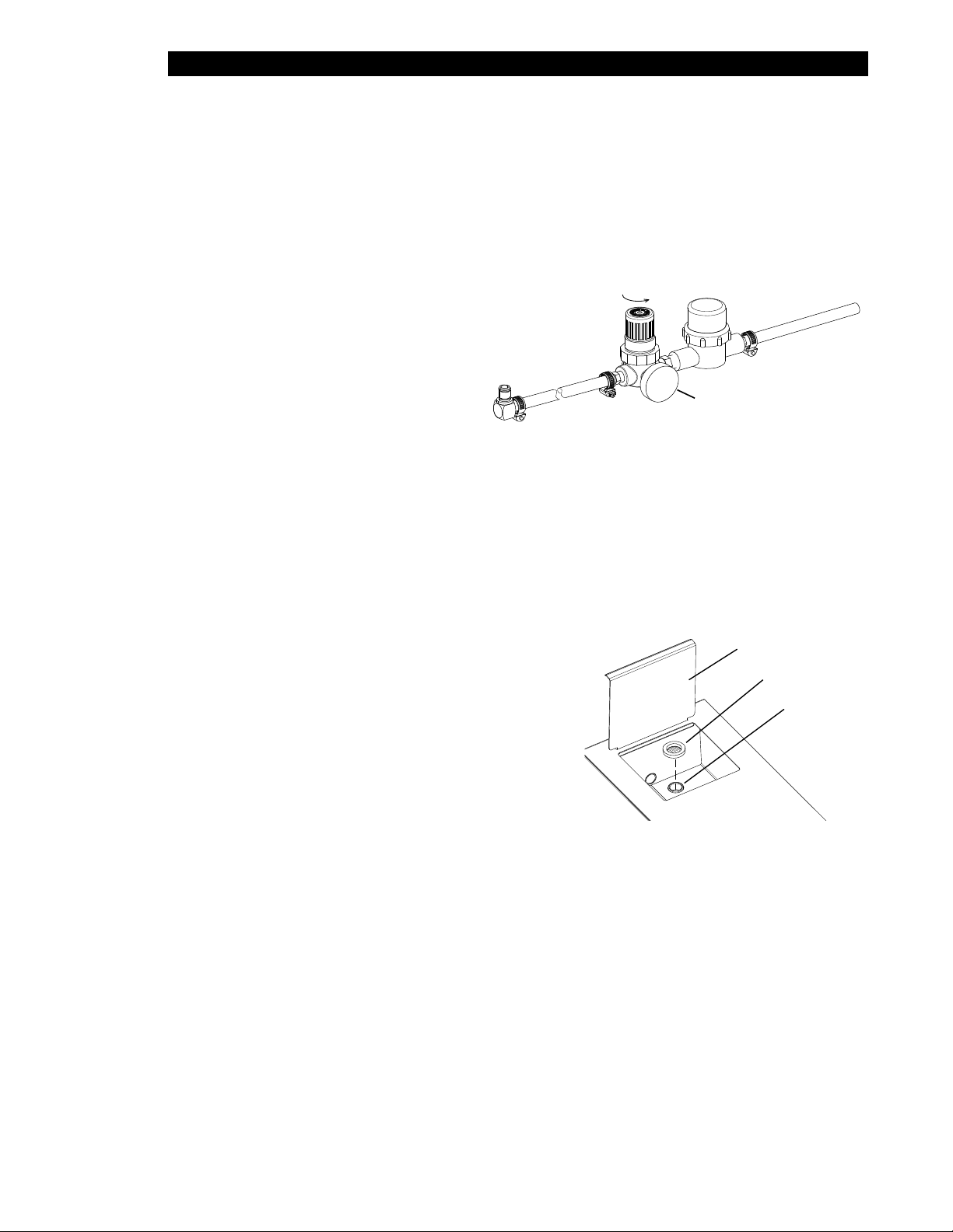
INSTALLATION continued
Filter
Regulator
To Steamer
Guage
Water
Source
26 psi
IL1532
Lid
WATER CONNECTION
These units come equipped with either a direct connect, rear mounted quick disconnect uid control
valve, or a 12 cup water tank with tank drain and supply pump. It is vital that all water supply lines be
thoroughly ushed with clean water before being connected to the steamer.
The Star Fast-Steamer has a water injection system, to ensure your new equipment works at its
premium, we recommend that a water softener is used in areas where hard water is present. Contact
your local water equipment system provider to assist you in determining your specic water quality, or
contact Star Technical support for assistance, 314-678-6303.
Direct Connect Water Supply Installation
1. Make certain the water valve that
will be suppling the unit is turned
off.
2. Connect the 1/4" I.D. exible
tubing to the outlet side of the water
source and secure with clamps
provided.
3. Holding the end opposite end
over a bucket, turn the water valve on until there is a good consistent supply of water
(this removes any air from the system and ushes it of any particles that may be present).
4. Turn off the water valve.
5. Push the check valve tting into the water inlet located on the rear of the unit.
Make certain the connection is securely attached by lightly tugging on it.
6. Turn on water valve, Turn the knob on the regulator until the guage reads 26 psi.
Check for leaks.
Reservoir Water Units
1. With unit in nal position, open reservoir lid.
2. Check and make sure the reservoir is free of debris
and material that may interfere with its operation.
3. The unit comes with a washer strainer which ts
over the water inlet (see illustration), verify this is
correctly in position. Periodically check strainer and
clean and replace as often as necessary.
4. Pour tap water into reservoir until the water level is
1/4" from the top.
5. Closed lid.
6. Check water level during daily operation and ll as needed.
Strainer
Water Inlet
IL1537
2M-Z10887 Owners Manual Fast Steamers
6
Page 7

CAUTION
OPERATING PROCEDURE
Connect your unit to a wall outlet which will supply the unit with the proper voltage specied on the
data plate. If you have a reservoir unit, verify the water level, add if water is low.
KEEP HANDS AND FACE AWAY FROM THE UNIT WHEN OPENING OR
REMOVING THE SPATULA FROM THE UNIT. STEAM ESCAPING IS VERY HOT.
MANUAL CONTROL
• Turn unit on
Wait 20 - 30 minutes for the unit to reach its operating temperature before using.
Note: The Temperature Set Point is factory xed at 400°F (204°C) and is not adjustable.
• Place product in cooking chamber and hit the Steam Shot button to steam the product.
Steam Shot: Pressing the Green Steam Shot Green Button will release water in to the steam
generator and will instantly produce steam. Water will only stop when the button is released.
Flooding of the steam generator may occur if the Steam Shot button, or the SST is set to high. When
this occurs wait for the unit to work through the water before applying more water to the steam
generator.
ELECTRONIC CONTROL
• Turn unit on
Current Temperature will Flash on LED, PRESS the
TEMP button to see current temperature
TCT will FLASH until TSP (Temperature Set Point) is reached,
Alarm will sound 3-times when TSP is reached.
Note: The Temperature Set Point is factory xed at 400°F (204°C) and is not adjustable.
• Place product in cooking chamber and choose one of the 4 pre-determined programmed
settings, or hit the Steam Shot steam button to steam the product.
• When program timing is completed, an alarm will sound.
PROGRAMMING DEFINITIONS
TCT Total Cook Time
SIT Shot Interval Time
SST Steam Shot Time
TSP Temp Set Point
Steam Shot: Pressing the Green Steam Shot Button will release water in to the steam generator
and will instantly produce steam. Water will only stop when the button is released. Flooding of the
steam generator may occur if the Steam Shot button, or the SST is set to high. When this occurs wait
for the unit to vaporize all of the water before applying more water to the steam generator.
TIMER & STEAMER CONTROLLER OPERATION SPECIFICATIONS
Startup:
1. The preset time will ash until the operating temperature is reached.
2. When the control reaches preset temperature, time display, "Heat On" indicator and program
indicator will stop ashing and the alarm will beep three times.
Temperature:
1. To view the actual steam generator temperature, press and hold "Temp Button."
2M-Z10887 Owners Manual Fast Steamers
7
Page 8
OPERATION continued
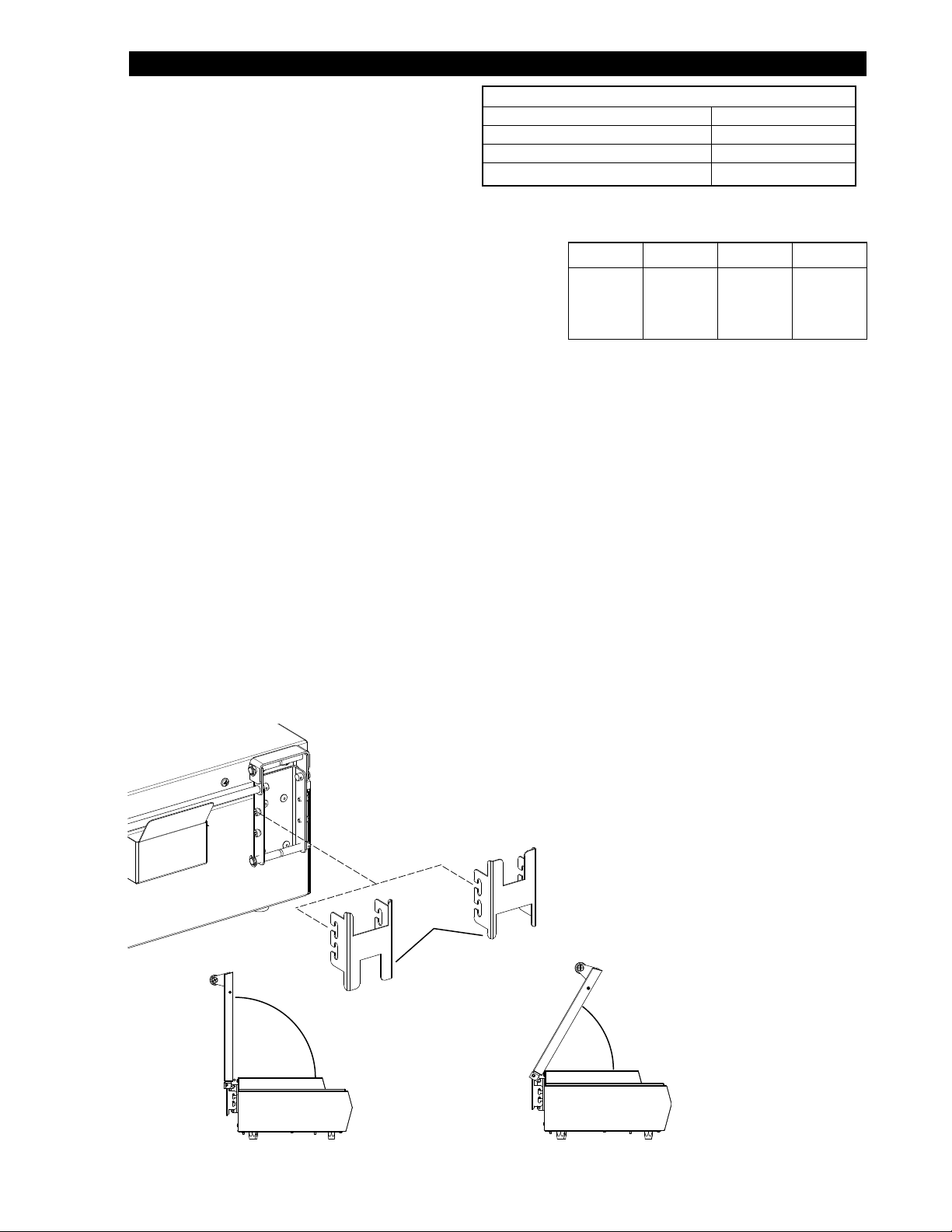
90 degrees
60 degrees
Cover
Stop
IL1366
To Program Time:
The program buttons factory pre-set are listed below.
If changes are required follow these simple steps.
Note, any changes to these settings are stored in
the units memory until changed. Returning to the
PROGRAMMING SPECIFICATIONS / RANGE
TCT Total Cook Time 0 to 99.59 minutes
SIT Shot Interval Time .5sec to 10 minutes
SST Steam Shot Time .1 sec to 5.minutes
TSP Temp Set Point
factory pre-sets is not available automatically.
1. Press and hold "TEMP"
(actual temperature displays).
2. While holding "TEMP," press and hold any
program button for one second, to begin
programming
3. TCT (Total Cook Time) will display, adjust
TCT 20 sec 40 sec 1 min 1.30 min
SIT 20 sec 40 sec 40 sec 40 sec
SST .5 sec .5 sec .5 sec .5 sec
Program Button Factory Presets
1 2 3 4
time with the "3 or 4" buttons.
• Press the #1 button to move to between minutes and seconds.
• Press the #1 button to move to SIT.
4. SIT (Shot Interval Time) will display, adjust time with the "3 or 4" buttons.
• Press the #1 button to move to between minutes and seconds.
• Press the #1 button to move to SST.
5. SST (Steam Shot Time) will display, adjust time with the "3 or 4" buttons.
• Press the #1 button to move to seconds.
6. Press the "TEMP" button to save time settings and to exit programming mode for this
program. Your program will not be saved if this step is not done within 10 seconds.
7. Repeat process to program for additional programming
Hi-Limit Reset
A hi-limit reset monitors the temperature of the steam generator and will turn the power off to the unit to
prevent it from overheating. If this occurs, the unit will automatically reset when it has had enough time to
cool prior to returning to operation. If this occurs on a regular basis it may be a sign of a larger problem,
call your service agent or Star Manufacturing at
314-678-6303.
TOP LOADING COVER STOP
SETTINGS
Top Loading Fast Steamer models (FS1 &
FS2) are designed with adjustable cover
stops located on the back of the units. As
shown here you can adjust your unit's
top cover between an opening of 60°
- 90°.
2M-Z10887 Owners Manual Fast Steamers
8
Page 9

CLEANING
DO NOT USE CAUSTIC CLEANERS,
CAUTION
WARNING
CAUTION
USE A MILD DETERGENT TO WIPE DOWN EXTERIOR SURFACES, CLEAN
WITH DAMP CLOTH
Daily
1. Turn the unit OFF & unplug the unit from its power source before proceeding with any service
or cleaning procedure.
2. Remove and clean the removable items listed on the maintenance components illustration for
your specic model. Clean using warm water and mild detergent. DRY parts completely.
3. Wipe the exterior or the steamer with a damp cloth, then wipe dry. Note: drying all pieces
after cleaning will protect your nish from discoloration, any discoloration as a result from not
drying the equipment is not covered under warranty
4. Reinstall the unit, beginning with the Steam Vent.
Monthly
The Star Fast Steamer generates instant steam by means of its open generator, however the mineral
deposits in the water are left behind. A certain amount of deposits are needed for proper operation,
but a build-up of calcium & mineral deposits may cause poor performance. It is important to properly
maintain you steamer to ensure quality operation. Depending on your specic water conditions and
possibly any water ltration systems, you may need to clean your steamer more or less frequently.
DO NOT IMMERSE OR LET THE UNIT STAND IN WATER. DO NOT HOSE
DOWNTHE UNIT. KEEP THE UNIT AWAY FROM RUNNING WATER.
DO NOT SPLASH THE CONTROL HOUSING
CERTAIN WATER CONDITIONS MAY REQUIRE MORE FREQUENT CLEANING.
BEFORE CLEANING MAKE SURE POWER IS TURNED OFF AND UNIT IS
WARNING
UNPLUGGED.
IF A CHEMICAL CLEANER / DELIMER IS USED, BE CERTAIN IS IT SAFE FOR
CAST ALUMINUM. FOLLOW PROCEDURES, PRECAUTIONS PROVIDED WITH
CAUTION
2M-Z10887 Owners Manual Fast Steamers
THAT SPECIFIC PRODUCT.
9
Page 10

Steam Generator
Cleaning Steam Generator
1. Turn the unit OFF & unplug the unit from its
power source.
2. Remove and clean the removable items
listed on the maintenance components
illustration for your specic model. Clean
using warm water and mild detergent.
DRY parts completely.
3. With the steam generator cool, use a wire
brush or scrapper to loosen the mineral/
calcium deposits on the generator surface
and steam ports. Remove the loose builtup particles from the surface and wipe area
clean with damp cloth and reassemble the
unit.
NOTE: A certain amount of calcium deposits
are needed on the steam generator to ensure
proper steaming characteristics. If during
cleaning, the surface becomes free of all
calcium/mineral deposits, add tap water to the
generator surface and allow it to boil off. In
soft water conditions, a small amount of
lime will season it. (Seasoning Mixture,
.75 oz. baking soda, .75 oz. lime, 1 quart
water), use enough to cover bottom of the
steam generator, turn unit on and allow to
evaporate.
Excessive Mineral Build-up
4. Use a delimer solution, which is safe
for cast aluminum, on the steam
generator surface. Follow the
instruction provide with the delimer
solution.
5. Use a dry towel or sponge to remove
the delimer solution, then rinse with
clean water.
6. Install the diffuser, generator cover
secure with the wing nut as shown
here.
6. Plug the steamer power cord into
the power supply, and turn unit on.
7. Allow unit to reach operating
temperature.
Wing Nut
Generator
Cover
Diffuser
Steam Ports
Water Inlet
IL1359
Above: Inspect these area making sure they are
clean of deposits.
Below: Reinstall these parts before foperating the
steam feature during the cleaning procedure.
IL1377
CAUTION
KEEP HANDS AND FACE AWAY
FROM THE UNIT WHEN OPERATING THE UNIT. STEAM ESCAPING IS VERY
HOT.
8. Push the Green "Steam Shot" button several times to operate the steamer.
This removes any delimer solution from the generator surface.
9. Turn unit off, reinstall all remaining parts and return unit to operation.
10
2M-Z10887 Owners Manual Fast Steamers
Page 11

CLEANING FRONT LOADING STEAMER COMPONENTS ILLUSTRATION
Top Cover
Wing Nut
Generator Cover
Steam Generator
Food Compartment
Liner
Steam Vent
Diffuser
Steam Ports
IL1352
Rack
Spatula
2M-Z10887 Owners Manual Fast Steamers
Drip Pan
Typical Front Loading Steamer Shown
11
Page 12

OPERATION TROUBLESHOOTING
DIAGNOSTICS FOR ELECTRONIC CONTROL STEAMERS
Shorted Temperature Probe
Open-Circuit Temperature Probe
No Heat/No Steam
Relay Malfunction
Heat / No Steam Temperature To Cool
Less than 50 Ohms of resistance, if
a temperature probe is detected, the
output power will be shut-off to all relays.
if a temperature probe is detected, the
output power will be shut-off to all relays.
If relay malfunction is detected when the
temperature is below 150°F (66°C) for
30 minutes or reaches 500°F (260°C).
The output power will be shut-off to both
relays unit the error no longer occurs.
Probe Temperature is 200°F (93°C) less
than the programmed set point.
Press the “TEMP” switch,
the LED will display
“PrOB”
Press the “TEMP” switch,
the LED will display
“PrOB”
The display will blink
“rELY”
Program & Heat Indicator
Light will Flash.
If unit still does not operate contact the factory or one of its representatives or a local service
company for service or required maintenance.
12
Page 13

Visit our Website at: www.star-mfg.com Email: service@star-mfg.com
This unit has been tested for proper operation before leaving our plant to insure delivery of your unit in perfect condition. However, there are instances in which
the unit may be damaged in transit. In the event you discover any type of damage to your product upon receipt, you must immediately contact the transportation
company who delivered the item to you and initiate your claim with same. If this procedure is not followed, it may affect the warranty status of the unit.
All workmanship and material in Star products have a one (1) year limited warranty on parts & labor in the United States and Canada. Such warranty is limited
to the original purchaser only and shall be effective from the date the equipment is placed in service. Star's obligation under this warranty is limited to the repair
of defects without charge, by the factory authorized service agency or one of its sub-agencies. Models that are considered portable (see below) should be taken
to the closest Star service agency, transportation prepaid.
THOROUGHLY INSPECT YOUR UNIT ON ARRIVAL
LIMITED EQUIPMENT WARRANTY
> Star will not assume any responsibility for loss of revenue.
> On all shipments outside the United States and Canada, see International Warranty.
* The warranty period for the Ultra-Max, Hot Plates, Griddles, Charbroilers is (3) years parts & labor.
* The warranty period for the Star-Max, Charbroilers, Griddles, Hot Plates, Fryers & Finishing Oven is (2) years parts & labor.
* The warranty period for the JetStar six (6) ounce & Super JetStar eight (8) ounce series popcorn machines is two (2) years.
* ThewarrantyperiodfortheChrome-MaxGriddlesisve(5)yearsonthegriddlesurface.Seedetailedwarrantyprovidedwithunit.
* The warranty period for Dura-Tec coatings is one year under normal use and reasonable care. This warranty does not apply if damage occurs to
Dura-Teccoatingsfromimpropercleaning,maintenance,useofmetallicutensils,orabrasivecleaners,abrasivepads,productidentiersand
point-of-sale attachments, or any other non-food object tha comes in continuous contact with the roller coating. This warranty does not apply to the
“non-stick” properties of such materials.
> This warranty does not apply to "Special Products" but to regular catalog items only. Star's warranty on "Special Products" is six (6) months on parts
and ninety (90) days on labor.
> This warranty does not apply to any item that is disassembled or tampered with for any purpose other than repair by a Star Authorized Service Center or
the Service Center's sub-agency.
> This warranty does not apply if damage occurs from improper installation, misuse, wrong voltage, wrong gas or operated contrary to the Installation and
Operating instructions.
> This warranty is not valid on Conveyor Ovens unless a "start-up/check-out" has been performed by a Factory Authorized Technician.
Parts that are sold to repair out of warranty equipment are warranted for ninety (90) days. The part only is warranted, the labor to replace the part is NOT warranted.
SERVICES NOT COVERED BY WARRANTY
1. Traveltimeandmileagerenderedbeyondthe50mileradiuslimit
2. Mileage and travel time on portable equipment (see below)
3. Labor to replace such items that can be replaced easily during a daily cleaning
routine, ie; removable kettles on fryers, knobs, grease drawers on griddles, etc.
4. Installation of equipment
5. Damagesduetoimproperinstallation
6. Damages from abuse or misuse
7. Operated contrary to the Operating and Installation Instructions
8. Cleaning of equipment
9. Seasoning of griddle plates
Star will not honor service bills that include travel time and mileage charges for servicing any products considered "Portable" including items listed below.
These products should be taken to the Service Agency for repair:
* TheModel510FD,510FFFryer.
* TheModel526TOAToasterOven.
* TheModelJ4R,4oz.PopcornMachine.
*TheModel518CMA&526CMACheeseMelter.
* TheModel12MC&15MC&18MCPHotFoodMerchandisers.
* TheModel12NCPW&15NCPWNachoChip/PopcornWarmer.
* All Hot Dog Equipment except Roller Grills & Drawer Bun Warmers.
* All Nacho Cheese Warmers except Model 11WLA Series Nacho Cheese Warmer.
* All Condiment Dispensers except the Model HPD & SPD Series Dispenser.
* All Specialty Food Warmers except Model 130R, 11RW Series, and 11WSA Series.
* AllQCS/RCSSeriesToastersexcept Model QCS3 & RCS3 Series.
* All Fast Steamer Models except Direct Connect Series.
The foregoing warranty is in lieu of any and all other warranties expressed or implied and constitutes the entire warranty.
Should you need any assistance regarding the Operation or Maintenance of any Star equipment; write, phone, fax or email our Service Department.
In all correspondence mention the Model number and the Serial number of your unit, and the voltage or type of gas you are using.
PARTS WARRANTY
10. Voltage conversions
11. Gas conversions
12. Pilot light adjustment
13. Miscellaneous adjustments
14. Thermostat calibration and by-pass adjustment
15. Resettingofcircuitbreakersorsafetycontrolsorresetbuttons
16. Replacementofbulbs
17. Replacementoffuses
18. Repairofdamagecreatedduringtransit,delivery,&
PORTABLE EQUIPMENT
FOR ASSISTANCE
installationORcreatedbyactsofGod
ALL:
* Pop-Up Toasters
* Butter Dispensers
* Pretzel Merchandisers
(Model 16PD-A Only)
* Pastry Display Cabinets
* Nacho Chip Merchandisers
* Accessories of any kind
* Sneeze Guards
* Pizza Ovens
(Model PO12 Only)
* Heat Lamps
* Pumps-Manual
13
2M-4497-2 11/21/14
Page 14

SK2250 Rev. C 8/30/2007
Sheet 1 of 8
WIRING DIAGRAM
FS1DT & FS2DT
COMPLETE
A
4
2
E11
E12E1E2
E3
E4
E7 E6 E5
RTD PROBE
1
NC3
N02
COM
6
5
2
7
3
3
3
7
8
B
B
A
3
8
9
1
1
1
2
2
1
2
6
5
ELECTRONIC
CONTROL
(BACK SIDE)
PUSH BUTTON
POWER
SWITCH
HEATER RELAY
HIGH LIMIT
THERMOSTAT
TRANSFORMER
120V/10V
120V
SOLENOID
CONTROL BOX
MOUNTING PLATE
CONTROL PANEL
MOUNTING PLATE
HEATING
ELEMENT
4
BLACK WIRE (TYP)
WHITE WIRE (TYP)
SOLENOID
RELAY
10
10
10
10
CORDSET
120V: NEMA 5-15P
(SHOWN)
120VC: NEMA 5-20P
(NOT SHOWN)
B
BLACK WIRE (TYP)
WHITE WIRE (TYP)
CORDSET
120V: NEMA 5-15P
(SHOWN)
120VC: NEMA 5-20P
(NOT SHOWN)
B
HIGH LIMIT
THERMOSTAT
CONTROL PANEL
MOUNTING PLATE
ELECTRONIC
CONTROL
(BACK SIDE)
POWER
SWITCH
2
10
10
E4
E3
E11
E12E1E2
8
B
B
3
E7 E6 E5
3
1
1
2
2
2
5
1
6
2
7
3
5
6
10
10
PUSH BUTTON
NC3
N02
COM
TRANSFORMER
120V/10V
RTD PROBE
WIRING DIAGRAM
FS1RT & FS2RT
COMPLETE
PUMP
RELAY
2
DIODE AND WIRE
PART OF PUMP
MOUNTING PLATE
8
1
CONTROL BOX
9
Sheet 2 of 8
1
3
7
2M-Z10887 Owners Manual Fast Steamers
HEATER RELAY
120V PUMP
HEATING
ELEMENT
SK2250 Rev. C 8/30/2007
14
Page 15

CONTROL PANEL
BLACK WIRE (TYP)
WHITE WIRE (TYP)
CORDSET
120V: NEMA 5-15P
(SHOWN)
120VC: NEMA 5-20P
(NOT SHOWN)
WIRING DIAGRAM
FS1D & FS2D
MOUNTING PLATE
A
HIGH LIMIT
C
THERMOSTAT
POWER
SWITCH
2
4
CONTROL BOX
MOUNTING PLATE
B
120V SOLENOID
(SHOWN ON SIDE)
B
A
1
1
2
2
1
3
Sheet 3 of 8
PUSH BUTTON
NC3
N02
4
COM
1
2
3
STEAM GENERATOR
THERMOSTAT
HEATING
ELEMENT
C
SK2250 Rev. C 8/30/2007
CONTROL PANEL
MOUNTING PLATE
POWER
1
SWITCH
3
BLACK WIRE (TYP)
WHITE WIRE (TYP)
CORDSET
120V: NEMA 5-15P
(SHOWN)
120VC: NEMA 5-20P
(NOT SHOWN)
STEAM GENERATOR THERMOSTAT
STD MOUNTED ABOVE HIGH LIMIT
STEAM GENERATOER HIGH LIMIT THERMOSTAT
STD MOUNTING BELOW THERMOSTAT
2M-Z10887 Owners Manual Fast Steamers
CONTROL BOX
MOUNTING PLATE
PUSH BUTTON
1
1
B
B
2
2
2
2
3
NC3
N02
COM
1
HEATING
ELEMENT
WIRING DIAGRAM
FS1R & FS2R
Sheet 4 of 8
SK2250 Rev. C 8/30/2007
15
Page 16

SK2250 Rev. C 8/30/2007
WIRING DIAGRAM
FSFDT Sheet 5 of 8
NEMA 6-20P
CORDSET
FOR 208/240V
E11
E12E1E2
E3
E4
E7 E6 E5
RTD PROBE
NC3
N02
COM
6
5
2
7
3
3
3
7
8
B
3
8
9
1
1
1
2
2
2
6
5
ELECTRONIC
CONTROL
(BACK SIDE)
PUSH BUTTON
POWER
SWITCH
HEATER RELAY
TRANSFORMER
230V/10V
CONTROL BOX
MOUNTING PLATE
CONTROL PANEL
MOUNTING PLATE
1
5
5
6
HEATING
ELEMENT
SOLENOID
STD
MOUNTING
POSITION
(SHOWN ON
SIDE).
4
4
A
B
A
SOLENOID
RELAY
12 V
SOLENOID
HIGH LIMIT
THERMOSTAT
BLACK WIRE (TYP)
WHITE WIRE (TYP)
10
10
10
10
CONTROL PANEL
BLACK WIRE (TYP)
WHITE WIRE (TYP)
CORDSET FOR
208/240V
NEMA 6-20P
MOUNTING PLATE
POWER
SWITCH
5
A
B
6
1
1
2
2
4
2
2
6
PUSH BUTTON
5
4
NC3
N02
COM
WIRING DIAGRAM
FSFD
12 V SOLENOID
(SHOWN ON SIDE)
C
HIGH LIMIT
THERMOSTAT
CONTROL BOX
MOUNTING PLATE
B
A
Sheet 6 of 8
3
1
3
STEAM GENERATOR
THERMOSTAT
2M-Z10887 Owners Manual Fast Steamers
HEATING
ELEMENT
C
SK2250 Rev. C 8/30/2007
16
Page 17

CONTROL PANEL
BLACK WIRE (TYP)
10
WIRING DIAGRAM
FSFR
SK2250 Rev. C 8/30/2007
Sheet 8 of 8
NEMA 6-20P
1
1
2
2
NC3
N02
COM
PUSH BUTTON
CORDSET FOR
208/240V
B
2
3
CONTROL BOX
MOUNTING PLATE
STEAM GENERATOR THERMOSTAT
STD MOUNTED ABOVE HIGH LIMIT
HEATING
ELEMENT
POWER
SWITCH
CONTROL PANEL
MOUNTING PLATE
3
1
B
STEAM GENERATOER HIGH LIMIT THERMOSTAT
STD MOUNTING BELOW THERMOSTAT
2
SEE
DETAIL
A
1
DIODE AND WIRE
PART OF PUMP
INLINE FUSEHOLDER
W/4AMP FUSE
12 V PUMP
BLACK WIRE (TYP)
WHITE WIRE (TYP)
A & B - 1/4" MALE
W/BLACK WIRE LEADS
C & D - 3/16" MALE
W/WHITE WIRE LEADS
DETAIL A
TRANSFORMER
B
WHITE WIRE (TYP)
CORDSET
FOR 208/240V
NEMA 6-20P
HIGH LIMIT
THERMOSTAT
MOUNTING PLATE
ELECTRONIC
CONTROL
(BACK SIDE)
POWER
SWITCH
10
E4
E3
E11
E12E1E2
E7 E6 E5
8
B
B
5
6
6
3
2
2
DETAIL
2
SEE
3
1
1
1
2
A
5
5
6
7
3
PUSH BUTTON
10
10
NC3
N02
COM
INLINE FUSEHOLDER
W/4AMP FUSE
TRANSFORMER
40 VA 230V/12V
RTD PROBE
WIRING DIAGRAM
FSFRT
DIODE AND WIRE
PART OF PUMP
8
PUMP
RELAY
6
CONTROL BOX
MOUNTING PLATE
9
5
1
3
7
HEATER RELAY
12V PUMP
A & B - 1/4" MALE
W/BLACK WIRE LEADS
Sheet 7 of 8
DETAIL A
TRANSFORMER
HEATING
ELEMENT
C & D - 3/16" MALE
W/WHITE WIRE LEADS
SK2250 Rev. A 8/3/2007
2M-Z10887 Owners Manual Fast Steamers
17
Page 18

1
2
3
19
18
17
16
20
21
22
4
5
6
8
9
10
11
7
12
13
11
14
MODEL: FSF
Front Loading Steamer Main Body Assembly
15
2M-Z10887 Owners Manual Fast Steamers
STAR MANUFACTURING INTERNATIONAL, INC.
Rev. B 1/18/13SK2276
18
Page 19

PARTS LIST August 31, 2009, Rev. E
MODEL: FSFR, FSFD, FSFRT, FSFDT, Front Loading Fast Steamer Main Body
Fig NO Part Number Qty Description Application
1 C9-Z10101 1 TOP FRONT LOADING
2 2C-Z10133 2 NUT, WING 10-24 SS FRONT LOADING
3 C9-Z10095 1 COVER, CASTING FRONT LOADING
4 C9-Z10096 1 DISPERSER FRONT LOADING
5 2C-08-07-0285 1 SCREW 10-24X3/4X3/8 TYPE 2 HEX DBL END STL FRONT LOADING
6 C9-Z10069 1 RACK, WIRE STEAMER FRONT LOADING
6 C9-FS0313 1 LINER ASSEMBLY FSF STEAMER FRONT LOADING
7 C9-FS0373 1 SPATULA ASSEMBLY FRONT LOADING
8 2B-Z10069 1 SPATULA WIRE ASSY FRONT LOADING
9 2C-Z11259 1 BOLT CARRIAGE 3/8-16X1” SS FRONT LOADING
10 2A-Z11257 1 SPATULA HANDLE TUBE FRONT LOADING
11 2A-Z11258 2 SPATULA ANGLED WASHER FRONT LOADING
12 C9-Z10103 1 SPATULA FRONT LOADING
13 C9-Z9990 1 SPATULA FRONT FRONT LOADING
14 2R-09-WB-0027 1 HANDLE-BLK 3/8-16 HD698 FRONT LOADING
15 C9-Z10105 1 DRIP TRAY FRONT LOADING
16 2C-Z6925 6 SCREW,#8 X.5 TEK HW SS FRONT LOADING
17 C9-Z11250 1 DRIP TRAY SUPPORT FSF FRONT LOADING
18 2A-Z9989 4 FOOT, 2” STEAMER FRONT LOADING
19 2c-200015 2 SCREW, 8-32 X 3/8 KNURLED BR FRONT LOADING
20 C9-FS0301 1 VENT ASSEMBLY FRONT LOADING
21 C9-FS0344 1 FSF CASTING ASSEMBLY 208V FRONT LOADING 208V
21 C9-FS0345 1 FSF CASTING ASSEMBLY 230V FRONT LOADING 230/240V
22 2C-3033 12 SCREW-MACH 8-32X3/4 NPST FRONT LOADING
2M-Z10887 Owners Manual Fast Steamers
IMPORTANT: WHEN ORDERING, SPECIFY VOLTAGE OR TYPE GAS DESIRED PAGE 1
INCLUDE MODEL AND SERIAL NUMBER OF 1
Some items are included for illustrative purposes only and in certain instances may not be available.
Star Manufacturing International, Inc.
19
Page 20

23
21
2
1
3
4
5
6
7
8
9
18
21
20
16
17
16
19
15
22
24
10
11
12
13
14
MODEL FS1 & FS2
Main Body Assembly
2M-Z10887 Owners Manual Fast Steamers
STAR MANUFACTURING INTERNATIONAL, INC.
Rev. A 10/25/11SK2281
20
Page 21

PARTS LIST October 25, 2011, Rev. E
Model: FS1R, FS1D, FS1RT, FS1DT, FS2R, FS2D, FS2RT, FS2DT, Top Loading Fast Steamer Main Body
Fig No Part Number Qty Description Application
1 2C-4063 AR SCREW 10-24X1/2 SS THP FS1 & FS2
2
3 2C-Z9982 1 SCREW 3/8-16X1 PHFHMS SS FS1 & FS2
4 2A-Z9955 1 HANDLE MOUNTING BLOCK FS1 & FS2
5 2R-09-WB-0027 1 HANDLE-BLK 3/8-16X1 PHFHMS SS FS1 & FS2
6 2C-9042 3 SCREW 10-24X.75 FH SS FS1 & FS2
7
8
9
10
11 2C-Z4251 2 SCREW 8-32X3/8 RHP SS FS1 & FS2
12 C9-Z9987 1
13 C9-Z10488 1 PROBE HOLDER FS1/FS2 E/C - FS1RT, FS2RT, FS1DT, FS2DT
14 2C-1487 1 SCREW 6-32X1/4 RHP STL NP FS1RT, FS2RT, FS1DT, FS2DT
15
16
17 2A-Z3828 4 1” SOLID LEG FS1 & FS2
18
19 2C-Z2893 4 NUT 10-24 HEX STL ZP 9/16 WASHER FS1 & FS2
20 C9-Z10153 2 STEAM GENERATOR SUPPORT FS1 FS2 FS1 & FS2
21
22 2A-Z6604 4 SPACER, INSULATION PLATE FS1 & FS2
23
24
C9-FS0364
C9-FS0365 FS2
C9-FS0315
C9-FS0316 INSIDE COVER INSERT FS1 FS1
2I-Z10033
2I-Z10034 FS1
2B-Z10067
2B-Z5847 BUN RACK (SMALL) FS2
2D-Z10054
2D-Z10241 PAN, 2/3 PERFORATED FS2
C9-Z10174
C9-Z10175 BOTTOM FS1 FS1
2C-Z6925 14 SCREW #8 X 1/2 HEX WB SS FS1 & FS2
2C-Z6925 10 SCREW,#8 X.5 TEK HW SS FS2
C9-Z10482
C9-Z10483 ELEMENT INSULATION FS2 FS2D, FS2DT, FS2R, FS2RT
C9-Z10336
C9-Z10337 ELEMENT RETAINER FS2 FS2
2N-Z9983 1 ELEMENT FS1 120V 1800W FS1-120V
2N-Z9984 1 ELEMENT FS2 120V 1800W FS2-120V
C9-FS0378
C9-FS0397 FS2, WATER SPREADER ASSY FS2
1 COVER SKIN ASSY
INSIDE COVER INSERT FS2 FS2
1
1 FS2 COVER GASKET W/CLIPS
BOTTOM GRATE FOR 1/2 PAN FS1
1
1/2 PAN 2.5DP PERF SIDES - FS1
1
COVER DRIP CATCH FS1/2
BOTTOM FS2 FS2
1
ELEMENT INSULATION FS1 FS1D, FS1DT, FS1R, FS1RT
1
ELEMENT RETAINER FS1 FS1
2
FS1, WATER SPREADER ASSY FS1
1
FS1
FS2
FS1 & FS2
2M-Z10887 Owners Manual Fast Steamers
IMPORTANT: WHEN ORDERING, SPECIFY VOLTAGE OR TYPE GAS DESIRED PAGE 1
INCLUDE MODEL AND SERIAL NUMBER OF 1
Some items are included for illustrative purposes only and in certain instances may not be available.
Star Manufacturing International, Inc.
21
Page 22

32
31
32
33
37
28
Top Loading
40
12
36
13
33
28
Front Loading
14
15
16
1
2
3
28
30
7
8
29
4
28
5
6
1
1
9
10
11
Electronic Controls
12
40
11
13
Manual Controls
MODEL Fast Steamer
Control Box Assemblies
Direct Connect Water Supply
22
24
16
23
STAR MANUFACTURING INTERNATIONAL, INC.
Rev. B 6/21/12SK2277
2M-Z10887 Owners Manual Fast Steamers
22
Page 23

17
36
Top Loading
33
32
31
32
Front Loading
34
35
38
33
2
21
20
30
28
28
3
7
5
39
29
27
1
26
8
3
1
19
10
40
15
16
11
14
40
12
13
11
Electronic Controls
2M-Z10887 Owners Manual Fast Steamers
MODEL Fast Steamer
Control Box Assemblies
Reservoir Water Supply
12
13
Manual Controls
STAR MANUFACTURING INTERNATIONAL, INC.
6
22
24
23
16
Rev. A 6/21/12SK2385
23
Page 24

PARTS LIST May 29, 2013, Rev. E
Top & Front Loading Fast Steamer Control Box Assemblies
Fig No Part Number Qty Description Application
1 2C-Z4063 AR
C9-FS0300
2
C9-FS0305
3 2E-Z10158 2 RELAY, DPST-NO SEALED
2V-Z9981
4
2V-Z9988 SOLENOID VALVE 12V FSFD-208/240V FSFDT-208/240V
2T-Z10248
5
2T-Z10839 HL THERMOSTAT CAP-570 FSFD-208V
6 2T-Z10839 1 HL THERMOSTAT CAP-570 ALL
2E-05-07-0350
7
2E-05-07-0351 TRANSFORMER 115/10V 6VA FS1RT-120V, FS2RT-120V, FS1DT-120V, FS2DT-120V
2E-Z10170 TRANSFORMER, 40V 12V 115/230 FSFRT-208/240V, FSFR-208/240V
C9-FS0317
C9-FS0335 CB BTM ASSY FS1/2 DC MAN FS1D-120V, FS2D-120V
C9-FS0339 CB BTM ASSY FS1/2 DC EC FS1DT, FS2DT
C9-FS0341 CB BTM ASSY FS1/2 R EC FS1RT, FS2RT
8
C9-FS0343 CB BTM ASSY FS1/2 R MAN FS1R, FS2R
C9-FS0351 CB BTM ASSY FSF DC MAN FSFD-208/240V
C9-FS0352 CB BTM ASSY FSF R EC FSFRT-208/240V
C9-FS0360 CB BTM ASSY R MAN FSFR-208/240V
9 2K-Z10080 1 Q-D FEMALE/3/8 HOSE PANEL
C9-FS0311
10
C9-FS0314 CB BACK PNL ASSY DC
11 2E-Z1858 1 SWITCH-LIGHTED ALL
2M-Z10244
12
2M-Z10245 CONTROL PANEL LABEL MANUAL FS1D-120V, FS2D-120V, FSFD-208/240V, FS1R-120V, FS2R-120V, FSFR-208/240V
C9-FS0320
13
C9-FS0334 CONTROL PANEL ASSY M/C FS1D-120V, FS2D-120V, FSFD-208/240V, FS1R-120V, FS2R-120V, FSFR-208/240V
14 2K-Z1971 4 SPACER .257X.75X.25 NYLON
15 2J-Z9794 1 STEAMER CONTROL BOARD
16 2E-Z9991 1 SNAP PUSHBUTTON ASSY ALL
17 C9-Z10486 1 TANK LID FSF FS1/2 STEAMER
19 A3-35219 1 CAP & CHAIN
20 2C-Z2893 1 NUT 10-24 HEX STL ZP 9/16 WASHER FSFD-208/240V, FSFDT-208/240V, FSFR-208/240V, FSFRT-208/240V
21 C9-Z10481 1 PROBE/BULD HOLD DOWN BRKT FSFD-208/240V, FSFDT-208/240V, FSFR-208/240V, FSFRT-208/240V
SCREW 10-24X1/2 SS THP 18-8 OR 300
SERIES
CB COVER ASSEMBLY DC DIRECT CONNECT
1
CONTROL BOX COVER ASSY STEAMER
W/RESERVIOR
SOLENOID VALVE 120V STMR FS1DT-120V, FS2DT-120V, FS1D-120V, FS2D-120V
1
THERMOSTAT, 122F-483F FS1D, FS2D, FSFD, FS1R, FS2R, FSFR
1
TRANSFORMER 230V/10V 6VA FSFD-208/240V, FSFDT-208/240V
1
CB BTM ASSY FSF DC EC FSFDT-208/240V
1
CONTROL BOX BACK ASSY
1
CONTROL PANEL LABEL E/C
1
CONTROL PANEL ASSY E/C
1
FS1DT-120V,FS2DT-120V, FSFDT-208/240V, FS1D-120V, FS2D-120V, FSFD208/240V
FS1RT-120V, FS2RT-120V, FSFRT-208/240V, FS1R-120V, FS2R-120V, FSFR208/240V
FS1DT-120V, FS2DT-120V, FSFDT-208/240V, FS1RT-120V, FS2RT-120V, FSFRT208/240V
FS1DT-120V,FS2DT-120V, FSFDT-208/240V, FS1D-120V, FS2D-120V, FSFD208/240V
FS1RT-120V, FS2RT-120V, FSFRT-208/240V, FS1R-120V, FS2R-120V, FSFR208/240V
FS1DT-120V,FS2DT-120V, FSFDT-208/240V, FS1D-120V, FS2D-120V, FSFD208/240V
FS1DT-120V, FS2DT-120V, FSFDT-208/240V, FS1RT-120V, FS2RT-120V, FSFRT208/240V
FS1DT-120V, FS2DT-120V, FSFDT-208/240V, FS1RT-120V, FS2RT-120V, FSFRT208/240V
FS1DT-120V, FS2DT-120V, FSFDT-208/240V, FS1RT-120V, FS2RT-120V, FSFRT208/240V
FS1DT-120V, FS2DT-120V, FSFDT-208/240V, FS1RT-120V, FS2RT-120V, FSFRT208/240V
FS1RT-120V, FS2RT-120V, FSFRT-208/240V, FS1R-120V, FS2R-120V, FSFR208/240V
FS1RT-120V, FS2RT-120V, FSFRT-208/240V, FS1R-120V, FS2R-120V, FSFR208/240V
IMPORTANT: WHEN ORDERING, SPECIFY VOLTAGE OR TYPE GAS DESIRED PAGE
INCLUDE MODEL AND SERIAL NUMBER OF
Some items are included for illustrative purposes only and in certain instances may not be available.
Star Manufacturing International, Inc.
24
2M-Z10887 Owners Manual Fast Steamers
1
2
Page 25

PARTS LIST May 29, 2013, Rev. E
Top & Front Loading Fast Steamer Control Box Assemblies
A5-RG2036
22
C9-FS0357 CORD SET 120VCSA 120VC
C9-FS0362 CORD SET 12/3 6-20 6’ , 208/240V 208/240V
2K-Z2895
23
2K-Y6764 BUSHING - STRAIN RELIEF FSFD, FSFDT, FSFR, FSFRT
C9-FS0359
24
C9-Z10457 CORDSET MTG PLATE .88X.77
C9-Z10458 CORDSET MTG PLATE .88X.844 FSFD-208240V, FSFDT-208/240V, FSFR-208/240V, FSFRT-208/240V
26 C9-Z10220 2 PUMP MOUNTING STRAP
2U-Z10070
2U-Z9980
27
2U-Z12875
28 2C-Z10240
C9-Z10237
29
C9-Z10246 SOLENOID INLET HOSE FS1DT-
C9-Z10238
30
C9-Z10247 FS1/FS2 OUTLET HOSE FS1/FS2
C9-Z10456 FSF SOK OUT / TEE OUT HOSE FSFD, FSFDT
31 2K-Z9986 1
32 C9-Z10456
33 2A-Z9972 2 NIPPLE, PTFE 5.5” FSFD, FSFDT, FSFR, FSFRT
34 2E-Z10855 1 FUSE 4AMP .25X1.25 FSFRT-208/240V, FSFR-208/240V
C9-FS0308
35
C9-FS0330 FUSEHOLDER WIRE ASSY M/F FSFR-208/240V
36 2K-Z9978 1 HALF NIPPLE 1/8X2.5 FS1D, FS1DT, FS1R, FS1RT, FS2D, FS2DT, FS2R, FS2RT
37 2V-Z10448 1 STEAMER WATER SUPPLY HOSE
38 2E-Z3278 1 RTD PROBE - 48” LONG WIRE FS1DT, FS2DT, FS1RT, FS2RT, FSFDT, FSFRT
39 2I-Z11785 1 STRAINER, WASHER
40 2I-Z11291 1 SWITCH-BOOT ALL
CORD SET 120V W/TERMINALS, 120V
1
BUSHING HEYCO OCB-500 FS1D, FS1DT, FS1R, FS1RT, FS2D, FS2DT, FS2R, FS2RT
1
CORD SET 14/3 5-20P 6FT 120V-CUL
1
PUMP, OSCILLATING-12V FSFRT-208/240V, FSFR-208/240V
PUMP, OSCILLATING-115V, 22AMPS,
1
(mfg before 6/16/09)
PUMP, OSCILLATING-115V,38AMPS,
(mfg after 6/16/09)
4
CLAMP, HOSE 7/16-25/32
8 FSFD-208/240V, FSFDT-208/240V, FSFR-208/240V, FSFRT-208/240V
PUMP INLET HOSE FS1R, FS1RT, FS2R, FS2RT, FSFR, FSFRT
1
FSF PUMP OUTLET HOSE FSF STEAMER FSFRT-208/240V, FSFR-208/240V
1
UNION TEE, 3/8 SLIP-ON DOUBLE HOSE
BARB-STEAMER
2
FSF SOL OUT/TEE OUT HOSE FSF STEAMER
1 FSFR-208/240V, FSFRT-208/240V
FUSEHOLDER WIRE ASSY F/F FSFRT-208/240V
1
FS1D-120V, FS1DT-120V, FS1R-120V, FS1RT-120V, FS2D-120V, FS2DT-120V,
FS2R-120V, FS2RT-120V
FS1RT-120V, FS2RT-120V, FSFRT-208/240V, FS1R-120V, FS2R-120V, FSFR208/240V
FS1RT-120V, FS2RT-120V, FS1R-120V, FS2R-120V
FS1RT-120V, FS2RT-120V, FS1R-120V, FS2R-120V
FS1D-120V, FS1DT-120V, FS1R-120V, FS1RT-120V, FS2D-120V, FS2DT-120V,
FS2R-120V, FS2RT-120V
FSFD-208V
FSFD-208/240V, FSFDT-208/240V
FS1DT-120V, FS2DT-120V, FSFDT-208/240V, FS1D-120V, FS2D-120V, FSFD208/240V
FS1RT-120V, FS2RT-120V, FSFRT-208/240V, FS1R-120V, FS2R-120V, FSFR208/240V
2M-Z10887 Owners Manual Fast Steamers
IMPORTANT: WHEN ORDERING, SPECIFY VOLTAGE OR TYPE GAS DESIRED PAGE
INCLUDE MODEL AND SERIAL NUMBER OF
Some items are included for illustrative purposes only and in certain instances may not be available.
Star Manufacturing International, Inc.
25
2
2
Page 26

2
3
1
6
4
5
7
8
9
MODEL FS1 & FS2
Hinge Bracket Assembly
2
2M-Z10887 Owners Manual Fast Steamers
STAR MANUFACTURING INTERNATIONAL, INC.
Rev. - 8/28/07SK2315
26
Page 27

PARTS LIST October 25, 2011, Rev. E
Model: Top Loading Fast Steamer Hinge Assemblies
Fig No Part Number Qty Description Application
2A-Z10454
1
2A-Z10677 FS2
2 2A-Z10214 4 PIN, SPRING STEAMER ALL FS1 & FS2
3 C9-Z10156 2 HINGE/COVER BRACKET ALL FS1 & FS2
4 2C-Z10215 8 COTTER PIN 18-8 5/16 .059 ALL FS1 & FS2
5 2A-Z9992 2 HINGE PIN, OUTSIDE ALL FS1 & FS2
6 2C-Z4063 AR SCREW 10-24X1/2 SS THP
7 2P-Z10217 2 FS1 FS2 HINGE SPRING ALL FS1 & FS2
8 2A-Z10093 8 SCREW SHOULDER 8-32X3/16 ALL FS1 & FS2
9 C9-Z10452 2 COVER STOP FS1 FS2 ALL FS1 & FS2
1 CENTER HINGE PIN
FS1
2M-Z10887 Owners Manual Fast Steamers
Some items are included for illustrative purposes only and in certain instances may not be available.
Star Manufacturing International, Inc.
27
Page 28

STAR INTERNATIONAL HOLDINGS INC. COMPANY
Star - Holman - Lang - Wells - Bloomeld - Toastmaster
10 Sunnen Drive, St. Louis, MO 63143 U.S.A.
(314) 678-6303
www.star-mfg.com
28
 Loading...