

Page 1
CONVERTIBLE JET PUMP
QUICK REFERENCE
GUIDE
SEE INSTRUCTION
MANUAL FOR
COMPLETE DETAILS
EJECTORS
(Purchase separately)
Shallow Well Convertible Single Pipe
PIPE SIZES
1
3/4 in. Discharge
(1/2 & 3/4 HP)
1 in. Discharge
(1 & 1-1/2 HP)
1-1/4 in.
Suction
1 in.
Pressure
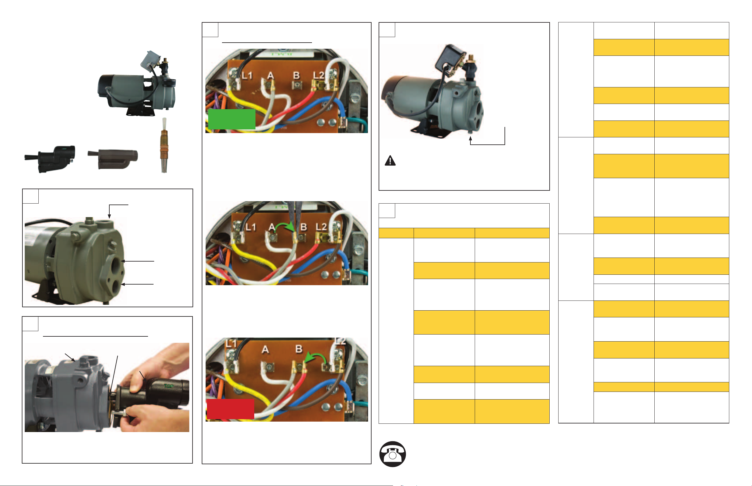
INSTALLATION
2
Shallow Well Application Only
Priming Port
Attach ejector to face of pump with two (2) bolts
and gasket provided. Venturi tube on the ejector
inserts into the top tapping of the face of the pump.
Venturi Tube
Ejector
ELECTRICAL CONNECTIONS
3
To change from 115V to 230V
115V
1. The motor of this pump is dual voltage and can
run on either 115V or 230V. In general, 230V is
more economical to run, and requires a smaller
wire size. 1/2 and 3/4 HP pumps are pre-set in
the factory to run at 115V. (Fig. 1)
2. For 230V service, change the following wires
on the terminal board:
a. Using a pair of needle nose pliers, pull the
gray wire with the female ag connector
from the “A” terminal spade post. Place it
to the right on the “B” terminal space post.
(Fig. 2a)
230V
b. Pull the red wire with the female ag
connector from the “L2” terminal. Place it to
the left on the “B” terminal space post.
(Fig. 2b)
WINTERIZING
4
PREVENT
PUMP
DAMAGE!
Remove plug
in freezing
weather
CAUTION: Drain the entire system if there
is danger of freezing. A drain plug is provided at
the bottom of the pump case for this purpose.
TROUBLESHOOTING
5
Problem Possible Cause Corrective Action
Little or no
discharge
1. Casing not
initially lled with
water
2. Suction lift too
high, or too long
3. Hole or air leak in
suction line
4. Foot valve too
small
5. Foot valve or
suction line not
submerged deep
enough in water
6. Motor wired
incorrectly
7. Casing gasket
leaking
8. Suction or
discharge line
valves closed
1. Fill pump casing
2. Move pump closer to
water source
3. Repair or replace.
Use pipe tape
and pipe sealing
compound
4. Match foot valve to
piping or install one
size larger foot valve.
5. Submerge lower in
water
6. Check wiring diagram
7. Replace
8. Open
SEE REVERSE FOR PRIMING INSTRUCTIONS
Questions? Call 1-800-742-5044
Copyright © 2011 Star Water Systems. All rights reserved.
Pump will
not deliver
water or
develop
pressure
Loss of
suction
Pump
vibrates
and/or
makes
excessive
noise
Pump will
not start or
run
BEFORE Returning Product
1. No priming water
in casing
2. Leak in suction
line
3. Discharge line
is closed and
priming air has
nowhere to go
4. Suction line (or
valve) is closed
5. Foot valve is
leaking
6. Suction screen
clogged
1. Air leak in suction
line
2. Suction lift too
high
3. Insufcient inlet
pressure or
suction head
4. Clogged foot
valve or strainer
1. Mounting plate
or foundation not
rigid enough
2. Foreign material
in pump
3. Impeller damaged 3. Replace
4. Worn motor
bearings
1. Improperly wired 1. Check wiring diagram
2. Blown fuse or
open circuit
breaker
3. Loose or broken
wiring
4. Stone or foreign
object lodged in
impeller
5. Motor shorted out 5. Replace
6. Thermal overload
has opened
circuit
1. Fill pump casing
2. Repair or replace
3. Open ball valve
4. Open
5. Replace foot valve
6. Clean or replace
1. Repair or replace
2. Lower suction lift,
install foot valve and
prime
3. Increase inlet
pressure by adding
more water to tank
or increasing back
pressure
4. Unclog
1. Reinforce
2. Disassemble pump
and clean
4. Replace
on motor
2. Replace fuse or close
circuit breaker
3. Tighten connections,
replace broken wiring
4. Disassemble pump
and remove foreign
object
6. Allow unit to cool,
restart after reason
for overload has been
determined
023539 A
Page 2
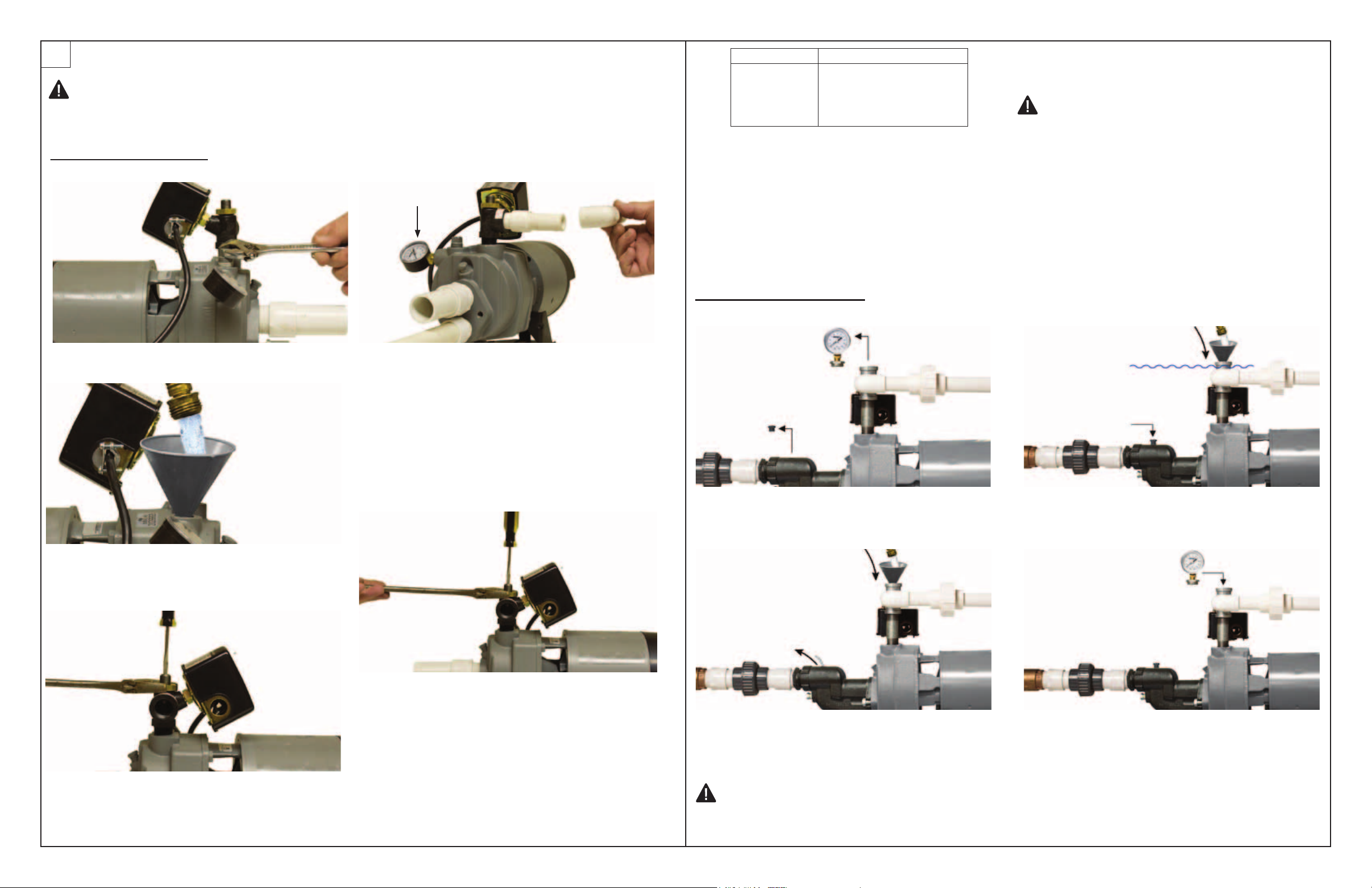
PRIMING
6
CAUTION: All pumps must be primed (lling the cavity with water) before they are rst
operated. This may take several gallons of water, as the suction line will be lled in addition to
the pump cavity.
Deep Well Application Only:
Pressure gauge
HP Pressure Setting
1/3
1/2
3/4
1
The correct control valve setting will depend on the
type of well installation and pressure switch setting
for the particular pump.
Shallow Well Application Only
24 PSI
27 PSI
38 PSI
46 PSI
NOTE: If the pump is being used for shallow well
applications, the ow control screw should be set in
the full open position.
IMPORTANT: If the pump fails to prime within
ve minutes:
Turn power off at the breaker box. Look for leaks
or a milky color in the discharged water, which
indicates an air leak. Re-prime if necessary,
following steps 1 through 5 above. Reset breaker at
the breaker box. All connections must be water and
air tight in order for pump to operate.
1. Remove the 1/2 in.priming plug. (Fig. 1)
2. Fill pump cavity with water until full and replace
priming plug. (Fig. 2)
4. If pump is properly primed, pressure will
quickly build and register on the gauge
mounted directly on the pump body. If
pressure does not build repeat priming
operation. All air must be vented from the
drive and suction pipes as well as the body
before the pump will prime. The pump body
may need to be lled several times in order to
achieve the prime. (Fig. 4)
Priming plug
with pressure
gauge
Air relief plug
1. Remove the 1/2 in. priming plug with pressure
gauge and air relief plug. (Fig. 1)
Water
level in
pump
cavity
3. Replace air relief plug and continue adding
water to pump cavity until water reaches the
top of the priming plug. (Fig. 3)
3. Tighten ow control screw completely by turning
clockwise, then loosen two turns. Now start the
pump. (Fig. 3)
5. With pump operating at high pressure, open
two or more faucets and slowly unscrew
the ow control screw until maximum ow
is obtained. This steady pressure will be
minimum operating pressure and should agree
with the pressure shown below. The ow
control screw diverts the proper amount of
water to operate the ejector. (Fig. 5)
2. Slowly ll pump cavity until water comes out of
air relief hole on top of the pump. (Fig. 2)
IMPORTANT: If the pump hums instead of pumping or turns off repeatedly, shut pump off immediately.
Check voltage. Make sure your incoming voltage matches the pump wiring voltage. See wiring guide in the
instructions.
4. Thread in priming plug and then open optional
ball valve if installed (see page 5) by turning
handle to line up with the pipe. (Fig. 4)
5. Turn on breaker to start pump
Copyright © 2011 Star Water Systems. All rights reserved.
 Loading...