

Page 1

®
®
®
®
®
TWO-SIDED
GRILLS
MODEL
CG10, GR10
CG14 & GR14
Installation and
Operation
Instructions
2M-Z2906 Rev. O 10/03/2014
14 x 14 Grooved Grill
Page 2

SAFETY SYMBOL
These symbols are intended to alert the user to the presence of
important operating and maintenance instructions in the manual
accompanying the appliance.
RETAIN THIS MANUAL FOR FUTURE REFERENCE
NOTICE
Using any part other than genuine Star factory supplied parts relieves the
manufacturer of all liability.
Star reserves the right to change specications and product design without
notice. Such revisions do not entitle the buyer to corresponding changes,
improvements, additions or replacements for previously purchased
equipment.
Due to periodic changes in designs, methods, procedures, policies and
regulations, the specications contained in this sheet are subject to change
without notice. While Star International Holdings Inc., Company exercises
good faith efforts to provide information that is accurate, we are not
responsible for errors or omissions in information provided or conclusions
reached as a result of using the specications. By using the information
provided, the user assumes all risks in connection with such use.
MAINTENANCE AND REPAIRS
Contact your local authorized service agent for service or required maintenance.
Please record the model number, serial number, voltage and purchase date in the area below and have it ready when
you call to ensure a faster service.
Model No.
Serial No.
Voltage
Purchase Date
Authorized Service Agent Listing
Reference the listing provided with the unit
or
for an updated listing go to:
Website: www.star-mfg.com
E-mail Service@star-mfg.com
Service Help Desk
Business 8:00 am to 4:30 p.m. Central Standard Time
Hours:
Telephone: (314) 678-6303
Fax: (314) 781-2714
E-mail Parts@star-mfg.com
Service@star-mfg.com
Warranty@star-mfg.com
Website: www.star-mfg.com
Mailing Address: Star International Holdings Inc., Company
10 Sunnen Drive
St. Louis, MO 63143
U.S.A
2
2
Page 3
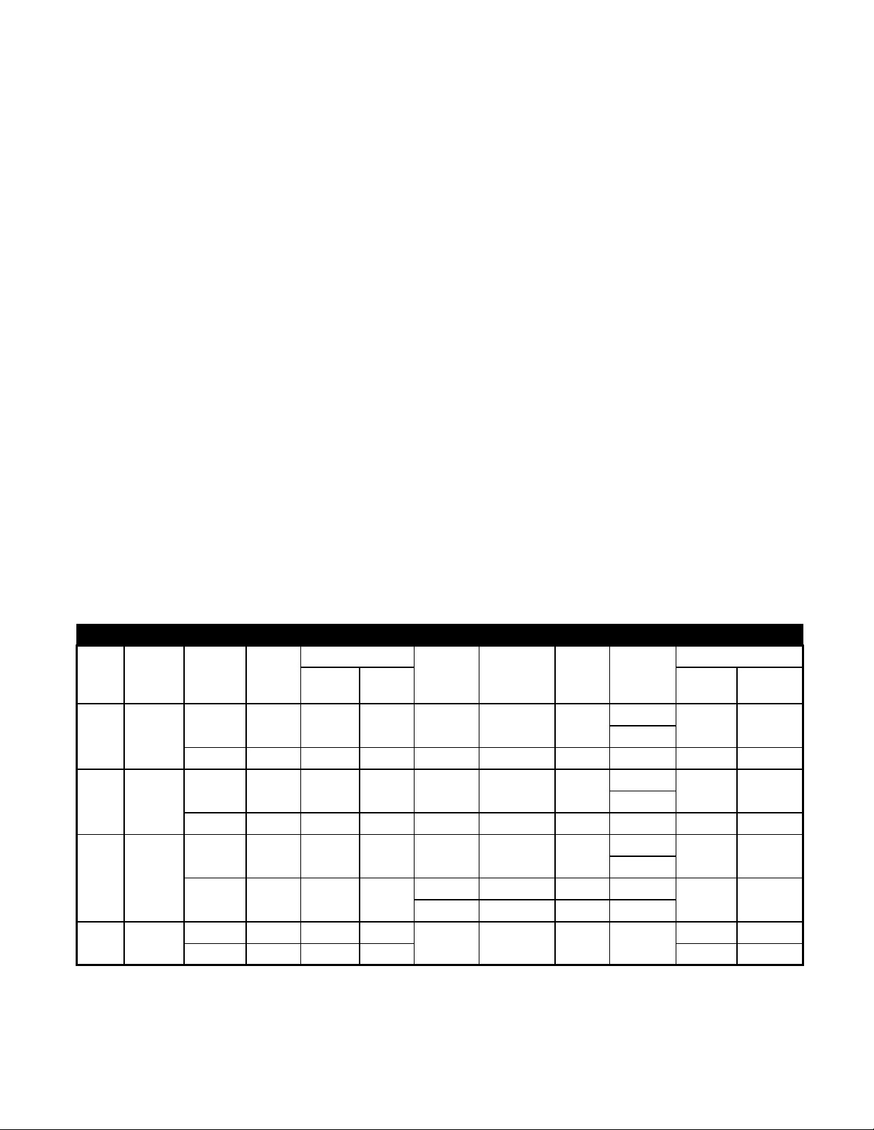
Model
No.
Grid
Surface
“A” Width “B” Depth
SPECIFICATIONS
Height
“C” Closed “D” Open Shipping Installed
Voltage Wattage Amps NEMA
Approx. Weight
GR10 Alum.
GR10I Iron
GR14 Alum.
GR14I Iron
16-1/8” 21-1/8” 14-1/4” 28-3/4” 120 1800 15
40.9 cm 53.7 cm 36.2 cm 73 cm 208/240 1350/1800 6.5/7.5 6-15P 23.6 kg 16.3 kg
16-1/8” 21-1/8” 14-1/4” 28-3/4” 120 1800 15
40.9 cm 53.7 cm 36.2 cm 73 cm 208/240 1350/1800 6.5/7.5 6-15P 30.4 kg 28.1 kg
19-5/8” 24-5/8” 14-1/4” 33” 120 1800 15
49.8 cm 62.5 cm 36.2 cm 83.2 cm
19-5/8” 24-5/8” 17-1/4” 36”
49.8 cm 62.5 cm 43.8 cm 91.4 cm 45.9 kg 39.4 kg
208/ 240 1350/1800 6.5/7.5 6-15P
230 1650 7.17 BS 1363A
208/240 2700/3600 13/15 6-20P
5-15P
5-20P*
5-15P
5-20P*
5-15P
5-20P*
52 lbs. 36 lbs.
67 lbs. 57 lbs.
67 lbs. 55 lbs
30.4 kg 24.9 kg
101 lbs. 87 lbs.
3
Page 4
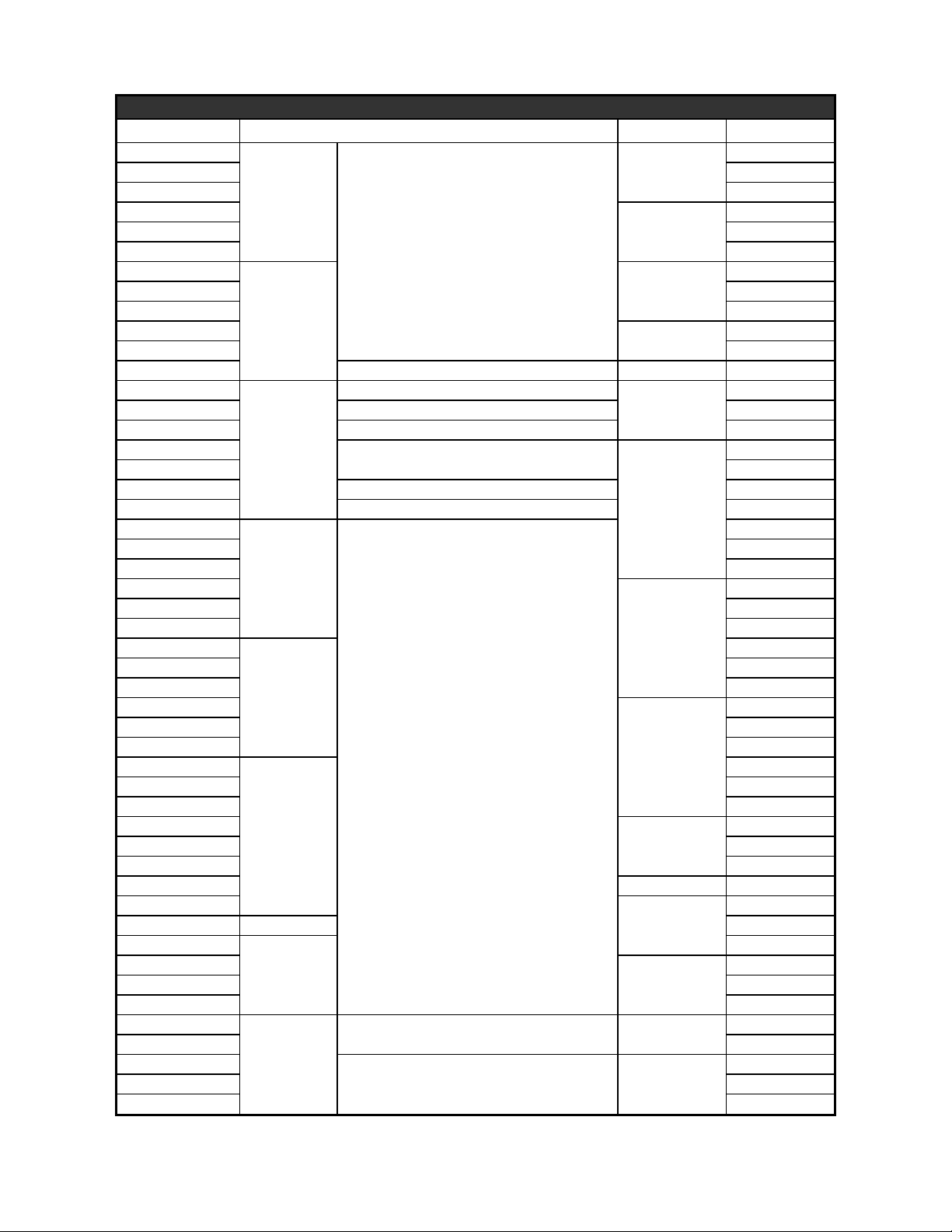
Specications
Model Platen Timer Country
CG10I-120V
without TimerCG10I-120VC Canadian
CG10I-240V
CG10IT-120V
CG10IT-240V
CG14-120V
CG14-240V
CG14-2T-120V
CG14-2T-120VC Canadian
CG14GTB-120V Smooth Bottom and Grooved Top Platens with Timer
CG14I-240V
CG14IGT-240V Grooved Top andSmooth Bottom Platens
CG14IT-120V
CG14IT-120VC Canadian
CG14IT-240V Grooved Top and Bottom Platens
CG14ITGT-240V Grooved Top andSmooth Bottom Platens
CG14T-120V
CG14T-120VC Canadian
CG14T-240V
GR10-120V
GR10-120VC Canadian
GR10-240V
GR10I-120V
GR10I-120VC Canadian
GR10I-240V
GR10IT-120V
GR10IT-120VC Canadian
GR10IT-240
GR10T-120V
GR10T-120VC Canadian
GR10T-240
GR14-120V
GR14-240V
GR14-2T-120VC with 2 Timers Canadian
GR14B-UK
GR14C-240V Chrome
GR14I-240V
GR14IT-120V
GR14ITB-120V
GR14SN-120V
GR14SN-120VC Canadian
GR14T-120V
GR14T-120VC Canadian
GR14T-240V
CastIron
Aluminum
CastIron
Aluminum
CastIron
Aluminum
CastIron
Aluminum
with TimerCG10IT-120VC Canadian
Grooved Top and Bottom Platens
without TimerCG14-120VC Canadian
with 2 Timers
Grooved Top and Bottom Platens
without TimerCG14IB-120V Grooved Top and Bottom Platens w/New Hinge
Grooved Top and Bottom
with Timer
without Timer
Grooved Top and Bottom Platens
Snub NoseSmooth Top and Bottom without Timer
Smooth Top and Bottom Platens with Timer
with Timer
without TimerGR14-120VC Canadian
without Timer
with TimerGR14IT-240V
United Kingdom
4
Page 5

CAUTION
WARNING
GENERAL INSTALLATION DATA
This equipment is designed and sold for commercial use only by personnel trained and experienced
in its operation and is not sold for consumer use in and around the home nor for use directly by the
general public in food service locations.
Before using your new equipment, read and understand all the instructions & labels associated with
the unit prior to putting it into operation. Make sure all people associated with its use understand the
units operation & safety before they use the unit.
All shipping containers should be checked for freight damage both visible and concealed.
This unit has been tested and carefully packaged to insure delivery of your unit in perfect
condition. If equipment is received in damaged condition, either apparent or concealed, a
claim must be made with the delivering carrier.
Concealed damage or loss - if damage or loss is not apparent until after equipment is
unpacked, a request for inspection of concealed damage must be made with carrier within
15 days. Be certain to retain all contents plus external and internal packaging materials for
inspection. The carrier will make an inspection and will supply necessary claim forms.
VENTILATION AND CLEARANCES
The installation of any components such as a vent hood, grease extractors, and/or re
extinguishing systems, must conform to their applicable nationally recognized installation
standards and/or local building codes.
ELECTRICAL CONNECTION
Before making any electrical connection be sure to read data plate which is located at the bottom of
the unit.
WARNING
ELECTRICAL GROUNDING INSTRUCTIONS
This unit is equipped with a 3-prong (grounding) plug for your protection against shock hazard and
must be plugged directly into a properly grounded 3-prong receptacle.
DO NOT CUT OR REMOVE THIS PLUG OR GROUNDING PRONG FROM THE PLUG.
CONNECT/PLUG UNIT INTO DEDICATED A.C LINE ONLY SPECIFIED ON THE DATA PLATE
OF THE UNIT.
5
Page 6
ELECTRICAL SPECIFICATIONS
Model No. Volts Rated Wattage Amps NEMA Plug
GR 10 120 1800 15 5-15P
GR 10 240 1800 7.5 6-15P
GR 10I 120 1800 15 5-15P
GR 10I 240 1800 7.5 6-15P
CG 10I 120 1800 15 5-15P
CG 10I 240 1800 7.5 6-15P
Note: For Canada, 120 volt units listed above have NEMA 5-20P plug.
Model No. Volts Rated Wattage Amps NEMA Plug
GR 14 120 1800 15 5-15P
GR 14 240 1800 7.5 6-15P
CG 14 120 1800 15 5-15P
CG 14 240 1800 7.5 6-15P
GR 14I 240 3600 15 6-20P
CG14I 120 1800 15 5-15P
CG 14I 240 3600 15 6-20P
CG 14IGT 240 3600 15 6-20P
GR 14C 240 3600 15 6-20P
Note: For Canada, 120 volt units listed above have NEMA 5-20P plug and 12/3 gage cord.
INITIAL START UP
Level unit using the adjustable feet under the unit (approximately 1/2" adjustment).
Before using the unit for the rst time, clean and heat for approximately 30 minutes. The grill may emit a small
amount of smoke as the cooking surfaces reach 300-350°F. Do not be alarmed, as the smoke is caused by oils
associated with the manufacturing process and will stop when the grill reaches 400°F.
SEASONING THE COOKING SURFACES (NON CHROME SURFACES)
FIRST TIME SEASONING
Follow your company/corporate guidelines for seasoning cooking surfaces. or
1. Bring the grill to 300°F and leave it on while doing the next three steps.
2. Brush the cooking surfaces with a salt free liquid vegitable oil. If using an aerosol agent, rst apply into a cup
and then brush onto cooking surface.
3. Let sit for 20 minutes, and then wipe clean using a warm damp cloth.
DAILY SEASONING
The grill should not require much seasoning while in use. In most cases, brush a light coating of a salt free liquid
vegitable oil in the morning and occasionally throughout the day will be enough to prevent any sticking. It is not
necessary to apply before grilling each item.
SETTING THE TEMPERATURE
The thermostat control knob is used to set the temperature to your requirements.
The maximum set point is 550°F (288°C), the minimum set point is 175°F (79°C).
See Knob Settings.
SETTING THE TIMER (TIMER MODELS ONLY)
(9 MIN. 59 SEC. MAX)
The timer may be factory pre-set. If changes are required follow these simple steps:
1. To increase time, press and hold the (UP) button.
The Start/Stop button can now be used to increase the cooking time.
2. To decrease time, press and hold the (DOWN) button.
The Start/Stop button can now be used to decrease cooking time.
When the timer reaches "00:00" the alarm will sound three times.
6
Page 7

KNOB SETTING
Knob Position Approx. Temp
1-2 175°F / 79°C
3 200°F / 93°C
4 250°F / 121°C
5 300°F / 148°C
6 350°F / 176°C
7 400°F / 204°C
8 450°F / 232°C
9 500°F / 260°C
10 550°F / 287°C
ON/OFF ROCKER SWITCH
(TIMER MODELS ONLY)
The switch turns the unit on and off. The switch has three positions:
With the switch in this position, both top and bottom platens will heat.
With the switch in this position, neither platen will heat.
With the switch in this position only bottom platen will heat.
DAILY OPERATION
Always allow 10-20 minutes of preheat time before loading the unit with product.
Failure to allow sufcient preheat time will result in unsatisfactory cooking of the rst load.
Check the power cord to insure that it is plugged into a proper outlet.
Check that the switch and thermostat control are turned on.
Set the unit's ON/OFF rocker switch to desired position.
Set the thermostat control knob to desired temperature.
OPERATING HINTS AND SAFETY
Disconnect power to the unit with the switch at the end of each day of operation.
Do not leave the unit in operation without an attendant.
Turn thermostat down to 200°F (93°C) during idle periods. It will take only a few minutes to regain
operating temperature.
Use spatula to push excess grease into grease drawer after each load of food is cooked. This will
reduce smoking of hot grease and carbonizing.
Do not leave the unit at high temperature when not in use or during idle periods. This will cause food
particles and grease lm to carbonize.
"Season" cooking surfaces with non-salted vegetable oil to reduce product sticking.
MONTHLY LUBRICATION/INSPECTION
Apply two (2) drops of non-toxic mineral or vegetable oil to counter balance shoulder rivets and plastic
spacers.
Check and clean brass rollers to make sure they are rolling and not sliding on the cam
surfaces of the counterbalance.
Check the bolts, screws and nuts, tighten if necessary.
7
Page 8

CLEANING (NON CHROME SURFACES)
Begin cleaning procedure by using the operating procedures within your organization, or follow the
steps below:
1. If particles adhere to the cooking surface during the day, scrape them off with a spatula.
NOTE: It is best not to let food cook onto the grill, as food build-up on the grill will increase
sticking and smoking. In addition, carbon may build up on the grill surface and reduce the cooking
efciency.
CARBON BUILDUP: A black matter that forms on or near the cooking surface. Generally this is
a combination of: releasing agents, oils, food particles etc. that has cooked itself to the surface.
After a period of time without cleaning, this will reduce performance and material may start aking
off. When that happens, follow the "Carbon Cleaning" procedures.
2. At the end of the day, wipe down all surfaces with a warm, damp cloth and mild detergent, then
dry.
CARBON CLEANING
When carbon build up occurs, use a carbon removal agent according to the instructions provided with
the cleaner. When this process is complete, you must re-season the grill according to your company/
corporate guidelines, or the seasoning instructions in this manual.
DO NOT IMMERSE OR LET THE UNIT STAND IN WATER.
CAUTION
DO NOT HOSE DOWN THE UNIT OR THE TABLE/COUNTER IF THE UNIT IS ON THE
TABLE/COUNTER.
KEEP AWAY FROM RUNNING WATER.
DO NOT USE SHARP OBJECTS TO REMOVE CARBON BUILD-UP.
BEFORE CLEANING MAKE SURE POWER IS TURNED OFF, UNIT IS UNPLUGGED AND IS
NOT TOO HOT.
While holding top lid with one hand, apply only cleaners which are safe for aluminum and
iron surfaces. Wipe with clean sponge or towel until unit is clean.
DO NOT SPLASH FRONT CONTROL PANEL!
DO NOT SPLASH FLEX CONDUIT CONNECTING TOP AND BOTTOM OF THE UNIT.
Remove and empty to clean grease catcher drawer as required using mild detergent and water.
WARNING
Do not use ice or cold water to clean the cooking surfaces when the unit is hot.
The surfaces are cast aluminum or cast iron and may crack or deform under the shock of rapid
temperature change.
CLEANING (CHROME SURFACES)
It takes very little time and effort to keep this Industrial Chromium griddle surface sparkling clean and
performing at top efciency. DO NOT allow grease to accumulate as it will carbonize and become
difcult to remove. To prevent this condition the following cleaning suggestions should be followed:
1. Remove excess grease and food regularly with a 4” (100mm) wide Razor Sharp type scraper with
rounded corners and wipe surface with a damp cloth if desired.
2. Following the scraping, for end of the day cleaning, a damp cloth and a non-silicated, non-abrasive,
non-chlorinated cleaner such as Bon-Ami may be used to wipe surface clean, followed by wiping
with a clean wet cloth.
3. Use a clean cloth and good non-abrasive cleaner to clean the (NON COOKING SURFACES)
stainless steel body of the griddle. Wipe the control panel front with a soft cloth.
4. At least once a day, remove the waste drawer and wash in the same way as an ordinary cooking
utensil. The drawer is removed by pulling forward and out.
8
Page 9

CAUTION
1. Never use pumice, griddle stones, or abrasives on a chromium surface.
2. Never strike a chromium griddle surface with a sharp instrument or spatula edge.
3. Never use steel wool.
4. Never use commercial liquid grill cleaner on the griddle surface.
5. Abusing surface voids the warranty.
CHROME SURFACE LIMITED WARRANTY EXCLUSIONS
Your Chrome Two Sided Grill has been designed to give you many years of cooking reliability and
requires minimum maintenance to keep the chrome surface in its original condition. All Chrome
surfaces are warranted for a period of 1 years against manufacturing defects to the original owner
from the date of installation. This limited warranty is void if it is determined by Star Manufacturing
International Incorporated or one of its authorized representatives that the chrome surface has been
misused or abused or subjected to the following situations:
1. Improperly installed.
2. Incorrect voltage applied to electric Pro-Max units allowing the surface to overheat and discolor.
3. The misuse of any instrument or tool which scratches or makes indentations in the surface which
could cause the surface to peel, ake, or chip off.
4. The use of any chemical or abrasive cleaning solution, griddle brick, stone, screen or other
cleaning products which could damage and affect the performance of the chrome surface.
5. The neglect of daily routine maintenance to the chromium surface.
OPERATION TROUBLESHOOTING
1. Unit not heating.
A. Check if unit is plugged in correct receptacle.
B. Check incoming power line.
C. Check that the switch is in correct position.
D. Check that thermostat is set to proper temperature.
2. Top platen not heating.
A. Check that the rocker switch is in correct position.
3. Counter balance roller not rolling.
A. Clean rollers.
If unit still does not operate contact the factory or one of its representatives or a local service
company for service or required maintenance.
9
Page 10

Visit our Website at: www.star-mfg.com Email: service@star-mfg.com
This unit has been tested for proper operation before leaving our plant to insure delivery of your unit in perfect condition. However, there are instances in which
the unit may be damaged in transit. In the event you discover any type of damage to your product upon receipt, you must immediately contact the transportation
company who delivered the item to you and initiate your claim with same. If this procedure is not followed, it may affect the warranty status of the unit.
All workmanship and material in Star products have a one (1) year limited warranty on parts & labor in the United States and Canada. Such warranty is limited
to the original purchaser only and shall be effective from the date the equipment is placed in service. Star's obligation under this warranty is limited to the repair
of defects without charge, by the factory authorized service agency or one of its sub-agencies. Models that are considered portable (see below) should be taken
to the closest Star service agency, transportation prepaid.
THOROUGHLY INSPECT YOUR UNIT ON ARRIVAL
LIMITED EQUIPMENT WARRANTY
> Star will not assume any responsibility for loss of revenue.
> On all shipments outside the United States and Canada, see International Warranty.
* The warranty period for the Ultra-Max, Hot Plates, Griddles, Charbroilers is (3) years parts & labor.
* The warranty period for the Star-Max, Charbroilers, Griddles, Hot Plates, Fryers & Finishing Oven is (2) years parts & labor.
* The warranty period for the JetStar six (6) ounce & Super JetStar eight (8) ounce series popcorn machines is two (2) years.
* The warranty period for the Chrome-Max Griddles is ve (5) years on the griddle surface. See detailed warranty provided with unit.
* The warranty period for Teon/Dura-Tec coatings is one year under normal use and reasonable care. This warranty does not apply if damage occurs to
Teon/Dura-Tec coatings from improper cleaning, maintenance, use of metallic utensils, or abrasive cleaners, abrasive pads, product identiers and
point-of-sale attachments, or any other non-food object tha comes in continuous contact with the roller coating. This warranty does not apply to the
“non-stick” properties of such materials.
> This warranty does not apply to "Special Products" but to regular catalog items only. Star's warranty on "Special Products" is six (6) months on parts
and ninety (90) days on labor.
> This warranty does not apply to any item that is disassembled or tampered with for any purpose other than repair by a Star Authorized Service Center or
the Service Center's sub-agency.
> This warranty does not apply if damage occurs from improper installation, misuse, wrong voltage, wrong gas or operated contrary to the Installation and
Operating instructions.
> This warranty is not valid on Conveyor Ovens unless a "start-up/check-out" has been performed by a Factory Authorized Technician.
Parts that are sold to repair out of warranty equipment are warranted for ninety (90) days. The part only is warranted, the labor to replace the part is NOT warranted.
1. Travel time and mileage rendered beyond the 50 mile radius limit
2. Mileage and travel time on portable equipment (see below)
3. Labor to replace such items that can be replaced easily during a daily cleaning
routine, ie; removable kettles on fryers, knobs, grease drawers on griddles, etc.
4. Installation of equipment
5. Damages due to improper installation
6. Damages from abuse or misuse
7. Operated contrary to the Operating and Installation Instructions
8. Cleaning of equipment
9. Seasoning of griddle plates
Star will not honor service bills that include travel time and mileage charges for servicing any products considered "Portable" including items listed below.
These products should be taken to the Service Agency for repair:
* The Model 510FD, 510FF Fryer.
* The Model 526TOA Toaster Oven.
* The Model J4R, 4 oz. Popcorn Machine.
* The Model 518CMA & 526CMA Cheese Melter.
* The Model 12MC &
* The Model 12NCPW & 15NCPW Nacho Chip/Popcorn Warmer.
* All Hot Dog Equipment except Roller Grills & Drawer Bun Warmers.
* All Nacho Cheese Warmers except Model 11WLA Series Nacho Cheese Warmer.
* All Condiment Dispensers except the Model HPD & SPD Series Dispenser.
* All Specialty Food Warmers except Model 130R, 11RW Series, and 11WSA Series.
* All QCS/RCS Series Toasters except Model QCS3 & RCS3 Series.
* All Fast Steamer Models except Direct Connect Series.
Should you need any assistance regarding the Operation or Maintenance of any Star equipment; write, phone, fax or email our Service Department.
15MC & 18MCP Hot Food Merchandisers.
The foregoing warranty is in lieu of any and all other warranties expressed or implied and constitutes the entire warranty.
In all correspondence mention the Model number and the Serial number of your unit, and the voltage or type of gas you are using.
SERVICES NOT COVERED BY WARRANTY
PARTS WARRANTY
10. Voltage conversions
11. Gas conversions
12. Pilot light adjustment
13. Miscellaneous adjustments
14. Thermostat calibration and by-pass adjustment
15. Resetting of circuit breakers or safety controls or reset buttons
16. Replacement of bulbs
17. Replacement of fuses
18. Repair of damage created during transit, delivery, &
PORTABLE EQUIPMENT
FOR ASSISTANCE
installation OR created by acts of God
ALL:
* Pop-Up Toasters
* Butter Dispensers
* Pretzel Merchandisers
(Model 16PD-A Only)
* Pastry Display Cabinets
* Nacho Chip Merchandisers
* Accessories of any kind
* Sneeze Guards
* Pizza Ovens
(Model PO12 Only)
* Heat Lamps
* Pumps-Manual
10
2M-4497-2 6/1312
Page 11

(ELEMENTO MAS BAJO)
BOTTOM ELEMENT
(ELEMENTO MAS ALTO)
TOP ELEMENT
5-15P PLUG STD
(NEGRO)
BLACK
(VERDE)
GREEN
(BLANCO)
WHITE
T-STAT
FRONT CONTROL PANEL
WIRE NO PART NO.
(HILO NO.) (PARTE NO.)
QTY.
(CANTIDAD)
1 D9-GR0103 1
2 D9-GR0104 1
3 D9-GR0105 1
PILOT
LIGHT
(BLOQUE TERMINAL)
TERM BLOCK
REAR PANEL
1
3
2
5-20P PLUG FOR CANADA
MODEL:
GR/CG10I-120V, GR/CG14I-120V
THIS DRAWING CONTAINS INFORMATION CONFIDENTIAL TO STAR MFG. INT'L. INC.
NO REPRODUCTION OR DISCLOSURE OF ITS CONTENTS IS PERMITTED.
STAR MANUFACTURING INTERNATIONAL INC.
SK1706 Rev A 6/13/2005
11
Page 12

TOP ELEMENT
230V UNIT
(ELEMENTO MAS ALTO)
INLET IEC 320 16A
G
BOTTOM ELEMENT
(ELEMENTO MAS BAJO)
N
19
L
18
BLACK
(NEGRO)
20
STAR MANUFACTURING INTERNATIONAL INC.
SK1707 Rev A 8/10/2004
REAR PANEL
FRONT CONTROL PANEL
3
2
GREEN
(VERDE)
WHITE
(BLANCO)
6-15P PLUG
TERM BLOCK
(BLOQUE TERMINAL)
1
QTY.
(CANTIDAD)
1 D9-GR0103 1
WIRE NO PART NO.
(HILO NO.) (PARTE NO.)
12
PILOT
LIGHT
T-STAT
GR/CG10I-230/240V, GR/CG14I-230/240V
2 D9-GR0104 1
3 D9-GR0105 1
18 D9-GR0250 1
19 D9-GR0251 1
20 D9-GR0252 1
NO REPRODUCTION OR DISCLOSURE OF ITS CONTENTS IS PERMITTED.
THIS DRAWING CONTAINS INFORMATION CONFIDENTIAL TO STAR MFG. INT'L. INC.
MODEL:
Page 13

230V UNITS
N
19
INLET IEC 320 16A
G
20
L
18
TOP ELEMENT
(ELEMENTO MAS ALTO)
REAR PANEL
BOTTOM ELEMENT
(ELEMENTO MAS BAJO)
FRONT CONTROL PANEL
STAR MANUFACTURING INTERNATIONAL INC.
SK1708 Rev A 8/10/2004
GREEN
(VERDE)
BLACK
(NEGRO)
WHITE
(BLANCO)
NEMA 6-20P PLUG
TERM BLOCK
(BLOQUE TERMINAL)
QTY.
WIRE NO PART NO.
3
1
(CANTIDAD)
2 D9-GR0104 1
1 D9-GR0103 1
(HILO NO.) (PARTE NO.)
2
PILOT
LIGHT
T-STAT
GR/CG10-230/240V, GR/CG14-230/240V
3 D9-GR0105 1
20 D9-GR0252 1
18 D9-GR0250 1
19 D9-GR0251 1
NO REPRODUCTION OR DISCLOSURE OF ITS CONTENTS IS PERMITTED.
THIS DRAWING CONTAINS INFORMATION CONFIDENTIAL TO STAR MFG. INT'L. INC.
MODEL:
13
Page 14

NEMA 5-15P ON ALL 120V UNITS.
15 AMP PLUG
NEMA 6-15P ON 240V, 1,800 WATT UNITS.
20 AMP PLUG
NEMA 6-20P ON 240V, 3,600 WATT UNITS.
GREEN
TOP ELEMENT
INLET IEC 320 16A
L N
18
19
230V UNITS
BOTTOM ELEMENT
TRANSFORMER
G
20
BLACK
WHITE
TERMINAL BLOCK
9
10
8
6
8
1
2
5
6
4
7
13
THERMOSTAT
INDICATOR LIGHT
(POWER ON)
TIMER BOARD
FOR REFERENCE
WIRING DIAGRAM IS SHOWN AS UNIT IS ASSEMBLED
WITH THE BOTTOM PLATE REMOVED. ITEMS ARE IN
GENERAL LOCATION BUT MAY BE RELOCATED OR SCALED
FOR CLARITY.
MODEL:
CG/GR, 10/14, 120V/230/240V,
WITH TIMER
THIS DRAWING CONTAINS INFORMATION CONFIDENTIAL TO STAR MFG. INT'L. INC.
NO REPRODUCTION OR DISCLOSURE OF ITS CONTENTS IS PERMITTED.
9
3
12
11
10
E2 E1
7
3
13
12
3
5 2
4
1
11
SWITCH
STAR MANUFACTURING INTERNATIONAL INC.
SK2001 Rev A
8/10/2004
14
Page 15

NORTH AMERICA:
UNITS WITH IEC CONNECTOR:
NEMA 5-15P ON 120V, 1,800 WATT UNITS FOR U.S. ONLY.
NEMA 5-15P ON 120V, 1,400 WATT UNITS FOR U.S. AND CANADA.
NEMA 5-20P ON 120V, 1,800 WATT UNITS FOR U.S. AND CANADA.
NEMA 6-15P ON ALL 240V, 1,800 WATT UNITS.
NEMA 6-20P ON ALL 240V, 3,600 WATT UNITS.
15 AMP PLUG
20 AMP PLUG
GREEN
BLACK
TRANSFORMER
IEC 320 C-20 POWER INLET, ON ALL 208 - 240V UNITS.
FOR USE WITH DETACHABLE CORDSETS SUPPLIED
WITH A STRAIGHT, FEMALE, IEC 60320 C-19 CONNECTOR.
POWER INLET CONNECTOR:
18
19
REAR OF CONNECTOR SHOWN.
TOP ELEMENT
WHITE
20
L N
E
G
BOTTOM ELEMENT
5
5
6
6
1
C
D
B
A
4
3
2
4
11
10
TERMINAL BLOCK
3
10
5
6
5
6
E2 E1
9
E2 E1
1
2
11
INDICATOR LIGHT
SWITCH
(INTERRUPTOR)
THERMOSTAT
FOR REFERENCE WIRING DIAGRAM IS SHOWN AS UNIT IS ASSEMBLED WITH THE
BOTTOM PLATE REMOVED. ITEMS ARE IN GENERAL LOCATION BUT MAY BE
WIRE DIAGRAM, CG/GR, 10/14, 120V/230/240V,
WITH 2 TIMERS, T-STAT, AND SPST SWITCH
SOME ITEMS ARE INCLUDED FOR
ILLUSTRATIVE PURPOSES ONLY AND IN
CERTAIN INSTANCES MAY NOT BE AVAILABLE
MODEL: SEE ABOVE
TIMER BOARD
RELOCATED OR SCALED FOR CLARITY.
STAR MANUFACTURING INTERNATIONAL, INC.
SK2387 REV. A 2-26-09
15
Page 16

GR14,GR14I, GR14ITTC,CG14,CG14I,CG14IGT
57
2
1
3
4
5
HOUSING ARM
CONNECTION
Earlier
Version
7
B
Version
69
68
7
73
72
71
70
54
54
53
24
9
PRECAUCION
Favorde no sumergir
o dejar que la base este
estancada sobre agua
No rocia con
manguera.
Maintengase lejos de
corriente de agua.
PELIGRO
FAVOR NO TOCAR
SUPERIFICIE
CALIENTE
Do not hose down.
Keep away from
running water.
DANGER
DO NOT TOUCH
HOT SURFACE.
69
6
10
68
CAUTION
Do not immerse or let
base stand in water.
67
66
9
11
12
14
52
19
51
65
64
63
62
61
67
66
13
17
15
16
17
16
27
28
56
29
B Style Hinge
30a
17
18
30
19
50
17
49
47
44
59
58
48
TOP &
BOTTOM
POWER ON
ON ( I )
BOTTOM
OFF
PRO-MAX
ON
POWER
TIME
START
STOP
45
46
SOME ITEMS ARE INCLUDED FOR
ILLUSTRATIVE PURPOSES ONLY AND IN
CERTAIN INSTANCES MAY NOT BE AVAILABLE
This drawing contains information confidential
to Star Manufacturing International, Inc.
No reproduction or disclosure of its
contents is permitted.
MODEL GR10I,CG10I,
20
26
25
21
Counterbalance
55
31
32
23
22
33
42
39
41
40
60
38
37
34
2M-Z2906 Two-Sided Grills
35
= B Style Hinge Units Only
STAR INTERNATIONAL HOLDINGS, INC. COMPANY
SK2455 Rev. E 10/03/2014
Page 17

PARTS LIST October 03, 2014, Rev. O
MODEL
Fig No Part No Qty Description Application
1 2C-Z2992 2 SCREW, HANDLE
2 2V-Z2990 1 HANDLE - 10”
3 2B-Z2988 2 ARM - 10”
4
5
6 D9-Z2038 1 HOUSING-TOP-10”
7 2C-Z3200 2 PIN - TOP HOUSING
8 2C-Z2855 2 RETAINER RING
9 2C-08-07-0040 2 1/4” NUT, USE WITH TOP HOUSING PIN
10 24-Z3827 1 CONDUIT KEEPER PLATE
11 2C-Z3780 2 CONDUIT RETAINER
12 2E-Z2898 1 CONDUIT ASSY. - PTFE
13 2E-Z3768 1 CONDUIT LOCKNUT
14
15 D9-Z14985 2 BRACKET, INSLUATION HOLD DOWN
16 D9-Z2908 2 INSULATION - 10”
17 2C-Z2893 8 NUT 10-24 HEX STL ZP
18 D9-Z2772
19 2C-08-07-0285 8 SCREW, ELEMENT RET. PLATE
20
21
22
23
24 2M-Z2620 1 LABEL CAUTION, BI-LINGUAL
25
26 2E-Z2894 1 TERMINAL BLOCK
27 D9-GR0053 1 REAR LINER ASSY. - 10”/BOT
28 2C-1512 2 SCREW - PIN ASSY
29 2V-Z3252 1 PIN ASSY - TOP HOUSING STOP
2M-Z2906 Two-Sided Grills
30
31 D9-GR0032 2 TORQUE BOX ASSY.
32 D9-Z3071 4 BRACKET-HANDLE
2C-40637
2C-08-07-0262 WASHER
2C-Z2992 4 SCREW, ARM TO BRACKET
2C-1523
2C-08-07-0262 LOCKWASHER, .250 INTERLOCK TOOTH
D9-04GR-0166
PS-Z1978
PS-Z2019 TOP ELEMENT, HEATING, 800W/240V GR10I, GR10IT, CG10I, CG10IT, GR10, GR10T
PS-GR0348
PS-GR0349 KIT, 2F-Z1932 CSTG, SM. TOP, IRON-10” GR10I, GR10IT
PS-GR0347 KIT, 2F-Z1934 CSTG, GR. TOP, IRON-10” CG10I, CG10IT
2K-Y3240
2K-Y6764 BUSHING - STRAIN RELIER (120C MODELS)
2E-Z2770
2E-Z2935 CORD SET 14/3 NEMA 5-15P
2E-Z4119 CORD, POWER, 12/3 5-20P 120C MODELS
2E-05-07-0350
2E-05-07-0351 TRANSFORMER 115/10V 6VA GR10T, CGR10IT, CG10IT, GR10IT4 (120V)
2R-Z2907
2R-Z3333 COUNTERBALANCE -10”-ALUM.
NUT 1/4-20 ACORN CAP MS
4
SCREW, .250-20UNC X .75 LG RHP
4
1 WIRE MOUNT
1 TOP ELEMENT/INS. PLATE/10
3 TOP ELEMENT/INS PLATE/10 CG10ITSB
TOP ELEMENT, HEATING, 800W/120 GR10I, GR10IT, CG10I, CG10IT, GR10, GR10T
1
KIT, 2F-Z1928 CSTG, SM. TOP,ALUM.-10” GR10, GR10T
1
BUSHING 90 SR 17-2
1
CORD, POWER, 14-3, 6-15P
1
TRANSFORMER 230V/10V 6VA GR10T, GR10IT, CG10IT (240V)
1
COUNTERBALANCE -10”-IRON
1
10' TWO SIDED GRILLS
B SERIES COUNTERBALANCE
GR10, GR10T, GR10I, GR10IT, CG10I, CG10IT,
(120&240V MODELS)
GR10T, GR10, GR10I, GR10IT, CG10I, CG10IT,
(240V MODELS)
GR10T, GR10, GR10I, GR10IT, CG10I, CG10IT,
(120V MODELS)
IMPORTANT: WHEN ORDERING, SPECIFY VOLTAGE OR TYPE DESIRED PAGE 1
INCLUDE MODEL AND SERIAL NUMBER OF 2
Some items are included for illustrative purposes only and in certain instances may not be available.
Star Manufacturing International, Inc.
Page 18

PARTS LIST October 03, 2014, Rev. O
MODEL
Fig No Part No Qty Description Application
33 2V-Z3072 2 HANDLE - SIDE
34 D9-GR0034 1 GREASE CABINET ASSY. All Models
35 D9-GR0517 1 GREASE DRAWER ASSY
D9-Z2711
37
D9-GR0246 230V MODELS
38 2A-Z11501 4 FOOT, 1” SOLID RUBBER
D9-GR0413
39
D9-GR0412 BODY ASSY. - 10” w/o TIMER GR10, GR10I, GR10I, CG10I, CG10I
D9-GR0460 BODY WELD ASSY CG10IT2-120V
40 2J-Z1836
2K-Z1971 4 SPACER CG10T, CG10IT, GR10T, GR10IT
41
2K-Z1971 8 SPACER .25X.75X.25 NYLON CG10IT2-120V
2J-Y6689
42
2J-Z2329 PILOT LIGHT, 240V GR10, GR10I, CG10I (240V MODELS)
2E-Z6863
2E-Z3808 SWITCH (EATON)-30A@120V CG10IT2-120V
44
PS-GR0223 SWITCH
2M-Z6881 1 OVERLAY - 10” w/TIMER GR10T, GR10IT, CG10IT
45
2M-Z11836 2 OVERLAY - 10” W/2 TIMERS CG10IT2-120V
2M-Z3051 1 OVERLAY - 10” NO TIMER GR10, GR10I, CG10I
46 2I-05-07-0013 1 RUBBER BOOT, SWITCH
47 2R-Z4621 1 KNOB-CONTROL
48 2T-6447 1 THERMOSTAT 118V-236V
49 2A-Z3026 1 HALF CLIP
50 D9-Z16492 2 INSULATION HOLD DOWN, BTM 10”
51 D9-Z2773 1 BTM ELEMENT RET. PLATE 10”
2N-Z1979 1 BTM ELEMENT, HEATING, 1000W/120 GR10I, GR10IT, CG10I, CG10IT, GR10, GR10T
52
2N-Z2020 1 BTM ELEMENT, HEATING, 1000W/240 GR10I, GR10IT, CG10I, CG10IT, GR10, GR10T
PS-GR0359 1 KIT, 2F-Z1929 CSTG, SM.BOT., ALUM.-10” GR10, GR10T
53
PS-GR0360 1 KIT, 2F-Z1933 CSTG, SM. BOT., IRON-10” GR10I, GR10IT
PS-GR0358 1 KIT, 2F-Z1935 CSTG, GR. BOT., IRON-10” CG10I, CG10IT
54 2C-Z5883 8 SCREW 10-24X1/2 FZA
55 PS-GR134 2 ROLLER BEARING KIT
56 D9-Z11283 1 COUNTER BALANCE STOP BASE ACCESSORIES
57 D9-Z11284 1 COUNTER BALANCE STOP, BRACKET ACCESSORIES
58 2M-Z18461 1 LABEL ON & OFF CG10IT2
D9-GR0550
D9-GR0552 120C MODELS
60
D9-GR0553 230V MODELS
1 BASE BOTTOM - 10”D9-Z12973 120VC MODELS
BODY ASSY. - 10” w/TIMER GR10T, GR10IT, CG10IT
1
1
TIMER CONTROL
2 CG10IT2
PILOT LIGHT, 120V GR10, GR10I, CG10I (120V MODELS)
1
SWITCH 3 POS CG10T, CG10IT, GR10T, GR10IT
1
1 BASE ASSY/GREASE CABINET
10' TWO SIDED GRILLS
CG10T, CG10IT, GR10T, GR10IT
CG10IT-120V W/SERIAL NO BELOW CGA24279
CG10IT-240V W/SERIAL NO BELOW CGA20294
GR10IT-120V W/SERIAL NO BELOW GRA27109
CG10TJD-240V W/SERIAL NO BELOW CGA29997
GR10T-240V W/SERIAL NO BELOW GRA03390
120/240V MODELS
2M-Z2906 Two-Sided Grills
IMPORTANT: WHEN ORDERING, SPECIFY VOLTAGE OR TYPE DESIRED PAGE 2
INCLUDE MODEL AND SERIAL NUMBER OF 2
Some items are included for illustrative purposes only and in certain instances may not be available.
Star Manufacturing International, Inc.
Page 19

PARTS LIST October 03, 2014, Rev. O
MODEL
Fig. No Part No Qty Description Application
1 2C-Z2992 2 SCREW, HANDLE
2V-Z11395
2
2V-Z2989 HANDLE - 14”, COUNTERBALANCE
2V-Z3413 HANDLE - 14” S.S.
2B-Z11391
2B-Z2987 ARM - 14”
3
2B-Z3336 ARM GR14SN
2B-Z14019 ARM, STANDARD 45 DEG.
2C-40637
4
2C-08-07-0262 WASHER
2C-Z2992 4 SCREW, ARM TO BRACKET
5
2C-1523
2C-08-07-0262 LCKWSHR, .250 INTERLOCK TOOTH
D9-Z2036 1 HOUSING-TOP-14”
6
D9-Z14020 1 TOP HOUSING, LEFT, 14”
7 2C-Z3200 2 PIN - TOP HOUSING
8 2C-Z2855 2 RETAINER RING
9 2C-08-07-0040 2 1/4” NUT, USE PART NUMBER 2C-Z2820
10 2A-Z3827 1 PLATE, STAMPING - CONDUIT
11 2C-Z3780 2 CONDUIT RETAINER
12 2E-Z2898 1 CONDUIT ASSY. - PTFE
13 2E-Z3768 1 CONDUIT LOCKNUT
14 D9-04-GR-0166 1 WIRE MOUNT
15 D9-Z13099 2 BRACKET, INSLUATION
16 D9-Z2888 2 INSULATION - 14”
17 2C-Z2893 8 NUT 10-24 HEX STL ZP
18 D9-Z2075 1 TOP ELEMENT/INS. PLATE/14
19 2C-08-07-0285 8 SCREW, ELEMENT RET. PLATE
PS-Z1980
PS-Z2021 ELEMNT REPL. KIT, 800W/240V CG14, CG14T, GR14, GR14T
D9-GR0535 ELEM\NT ASSY 800W/240V CG/GR14E-230V, CG/GR14E-240V
20
PS-Z2391 ELEMNT REPL, KIT, 1800W/240 GR14I, GR14IT, CG14IGT, CG14ITGT, CG14I, CG14IT
D9-GR0514 ELEMENT, TOP CG14E-120V, GR14E-120V, GR14IE
PS-GR0351
PS-GR0352 KIT, 2F-Z1948 CASTING GR14I, GR14IT
21
2M-Z2906 Two-Sided Grills
PS-GR0353 KIT, 2F-Z1950 CASTING CG14IGT, CG14ITGT
PS-GR0350 KIT, 2F-Z7786 CAST-TOP ALM GR14, GR14T
HANDLE, B-STYLE HINGE
1
ARM 14” SPT GR14SNB
2
NUT 1/4-20 ACORN CAP MS ALL EXCEPT GR14SNB MODELS
4
SCREW, .250-20UNC X .75 LG RHP
4
ELEMNT REPL. KIT, 800W/120V CG14, CG14T, GR14, GR14IB GR14T, CG14IT-120V
1
KIT, 2F-Z1946 CASTING CG14, CG14T, CG14GTB
1
14' TWO SIDED GRILLS
CG142TB, CG14B, CG14E, CG14IB, CG14IGTB, CG14ITB,
CG14ITGTB240, CG14ITLB, CG14ITSC, CG14TB, GR14B,
GR14E, GR14IB, GR14ITB, GR14SNB, GR14TB
GR14, GR14T, SER. # GRC00112 - 00138, GRC00778 - 00858,
GRC00864 - 01256
CG14EA, CG14IEA, GR14EA, GR14IEA, GR14C, CG14I,
CG14IGT, CG14IT, CG14ITGT, GR14, GR14I, GR14IT
CG14DTB, CG14B, CG14E, CG14IB, CG14IT, GR14B, GR14E,
GR14IB, GR14ITB
B SERIES COUNTERBALANCE
CG142TB, CG14B, CG14E, CG14IB, CG14IGTB, CG14ITB,
CG14ITGTB240, CG14ITLB, CG14ITSC, CG14TB, GR14B,
GR14E, GR14IB, GR14ITB, GR14SNB, GR14TB
IMPORTANT: WHEN ORDERING, SPECIFY VOLTAGE OR TYPE DESIRED PAGE 1
INCLUDE MODEL AND SERIAL NUMBER OF 4
Some items are included for illustrative purposes only and in certain instances may not be available.
Star International Holding, Inc. Company
Page 20

PARTS LIST October 03, 2014, Rev. O
14' TWO SIDED GRILLS
GR14I, GR14IT, CG14IGT, CG14ITGT, CG14I, CG14IT
(240V MODELS)
GR14I, GR14IT, CG14IGT, CG14ITGT, CG14I, CG14IT
(240V MODELS)
CG14, CG14T, GR14, GR14E, GR14T, GR14ITB, GR14IB,
(240V MODELS)
CG14-230V, CG14I-230V, CG14IT-230V, CG14ITGT-230, CG14T230V, GR14-230V, GR14I-230V, GR14IT-230V, GR14T-230V
CG14IB, CG14IGTB, CG14ITB, CG14ITLB, CG14ITSC, GR14IB,
GR14ITB
CG14I, CG14IB, CG14IE, CG14IEGT, CG14IGTB, GR14I GR14IB,
GR14IE, GR14ITB, (mfg after 4-2010)
MODEL
Fig. No Part No Qty Description Application
2K-3485
22
2K-Y2968 BUSHING 7W-2 CG14IT-120V
2K-Y3240 BUSHING SR 17-2, 90°
2K-Y6764 BUSHING - STRAIN RELIEF (120VC MODELS)
2E-Z2905
2E-Z2935 CORD SET 14/3 NEMA 5-15P (120V MODELS)
23
2E-Z2770
2E-Y9251 CORD SET CONT EUR 16 AMP 230V MODELS
2E-Z9192 CORDSET (DETACHABLE) UK GR14B-UK
2E-Z16940 CORDSET, 14/3, SJTO, 90°, 5-15 GR14TQ
24 2M-Z2620 1 LABEL CAUTION, BI-LINGUAL
2E-05-07-0350
25
2E-05-07-0351 TRANSFORMER 115/10V 6VA 120V MODELS
26 2E-Z2894 1 TERMINAL BLOCK
D9-GR0054
27
D9-GR0080 REAR LINER ASSY. - 14”/REAR CG14I, GR14I, CG14IGT, CG14IT, GR14IT, CG14ITGT
D9-GR0201 REAR LINER ASSY. CG14IT (120V)
28 2C-1512 2 SCREW - PIN ASSY
29 2V-Z3252 1 PIN ASSY - TOP HOUSING STOP
2R-Z2896
30
2R-Z2897 COUNTERBALANCE -14”-ALUM.
PS-GR0537
30a
PS-GR0538 KIT, HINGE & SPRING, 14” IRON 14” IRON, CG14B, GR14B SERIES
31 D9-GR0032 2 TORQUE BOX ASSY.
32 D9-Z3071 4 BRACKET-HANDLE
33 2V-Z3072 2 HANDLE - SIDE
34 D9-GR0034 1 GREASE CABINET ASSY.
35 D9-GR0517 1 GREASE DRAWER ASSY
D9-Z10086
37
D9-GR0519 BASE ASSY/GREASE CAB. 14” 120V & 240V MODELS
D9-GR0523 BASE BTM/GRS CAB ASM-230V 230V MODELS
2A-Z1485
2A-Z11501 FOOT, 1” SOLID RUBBER, 1/4” STUD ALLUMINUM PLATES
2A-Z0314-1 BASE, FOOT 4” CAST W/RUBBER FOOT
38
2A-Z12980 2.5” FOOT BASE, 3/8” STUD GR14I, GR14IT, CG14I, CG14IT, CG14IGT, CG14ITGT
2A-Z12946 BASE, FOOT, NON-SKID
D9-GR0061
39
D9-GR0184 BODY ASSY GR14SN
40 2J-Z1836 1 TIMER CONTROL CG14T, CG14IT, CG14IGT, GR14T, GR14IT
BUSHING-HEYCO #SR-9P-2
1
CORD SJTO 12/3 NEMA 6-20P
CORD, POWER, 14-3, 6-15P 240V, 72”
1
LONG
TRANSFORMER 230V/10V 6VA 230 & 240V MODELS
1
REAR LINER ASSY. - 14”/BOT CG14, GR14, CG14T, GR14T
1
COUNTERBALANCE -14”-IRON
1
KIT, HINGE & SPRING, 14” ALUMINUM 14” ALUMINUM, CG14B, GR14B SERIES
1
PLATE, BOTTOM GR14-2T-120C
1
FOOT, 1” ADJUSTABLE, 1/4” STUD CERTAIN APPLICATIONS
4
BODY ASSY. - 14”
1
2M-Z2906 Two-Sided Grills
IMPORTANT: WHEN ORDERING, SPECIFY VOLTAGE OR TYPE DESIRED PAGE
INCLUDE MODEL AND SERIAL NUMBER OF
Some items are included for illustrative purposes only and in certain instances may not be available.
Star International Holding, Inc. Company
2
5
Page 21

PARTS LIST October 03, 2014, Rev. O
MODEL
Fig. No Part No Qty Description Application
41 2K-Z1971 4 SPACER CG14T, CG14IT, CG14IGT, CG14E, GR14T, GR14IT, GR14E,
14' TWO SIDED GRILLS
2J-Y6689
42
2J-Y6690 PILOT LIGHT, 240V GR14I, CG14IGT, CG14I, CG14, GR14 (240V)
PS-GR0224
44
2E-Z6863 SWITCH 3 POS, DPDT CG14T, CG14IT, CG14IGT, GR14T, GR14IT
2E-Z3808 SWITCH - 30A@120V CG14E-120V, GR14E-120V
2M-Z3050
2M-Z3816 OVERLAY - 14” w/2 MANUAL TIMERS CG14-2T
45
2M-Z6870 OVERLAY - 14” w/TIMER GR14IT, CG14ITGT, CG14IT, CG14T, GR14T, GR14TB
2M-Z12002 OVERLAY CG14E, GR14E
2M-Z18461 LABEL ON & OFF CG14E, GR14E
46 2I-05-07-0013 1 RUBBER BOOT, SWITCH
47 2R-Z1854 1 KNOB-CONTROL
48 2T-6447 1 THERMOSTAT 118V-236V
49 2A-Z3026 1 HALF CLIP
50 D9-Z12885 2 INSULATION HOLD DOWN,
51 D9-Z13338 1 BTM ELEMENT RET. PLATE 14”
2N-Z1981
2N-Z2022 BTM ELEMENT, HEATING, 1000W/240 CG14, CG14T, GR14, GR14T
52
D9-GR0534 BTM ELEMENT ASSY, 1000W/240 GR14E-240V
2N-Z2392 BTM ELEMENT, HTG, 1800W/240V GR14I, GR14IT, CG14IGT, CG14ITGT, CG14I, CG14IT
D9-GR0513 BTM ELEMENT ASSY CG14E-120V, GR14E-120V, GR14IE
2F-Z1945
2F-Z1947 CASTING, GR. BOT., ALUM.-14” CG14, CG14T
53
2F-Z1949 CASTING, SM. BOT., IRON-14” GR14I, GR14IT, CG14IGT, CG14ITGT
2F-Z1951 CASTING, GR. BOT., IRON-14” CG14I, CG14IT
54 2C-Z5883 8 SCREW 10-24X1/2 FZA
55 PS-GR134 2 ROLLER BEARING KIT
56 D9-Z11283 1 COUNTER BALANCE STOP BASE ACCESSORIES
57 D9-Z11284 1 COUNTER BALANCE STOP BRACKET ACCESSORIES
PILOT LIGHT, 120V CG14, GR14 (120V MODELS)
1
CG14T-120V W/SERIAL NO BELOW CGC25308
RKER SWITCH RPL 14” KIT
1
OVERLAY - 14” NO TIMER
1
BTM ELEMENT, HEATING, 1000W/120 CG14, CG14T, GR14, GR14IB, GR14T, CG14IT-120V
1
CASTING, SM. BOT., ALUM.-14” GR14, GR14T, CG14GTB
1
CG14IT-120V W/SERIAL NO BELOW CGC24701
GR14T-120V W/SERIAL NO BELOW GRC23789
CG14IT-240V W/SERIAL NO BELOW CGC24559
GR14I, CG14IGT, CG14I, CG14, CG14B, GR14, GR14B,
CG14GTB
2M-Z2906 Two-Sided Grills
IMPORTANT: WHEN ORDERING, SPECIFY VOLTAGE OR TYPE DESIRED PAGE
INCLUDE MODEL AND SERIAL NUMBER OF
Some items are included for illustrative purposes only and in certain instances may not be available.
Star International Holding, Inc. Company
3
5
Page 22

PARTS LIST October 03, 2014, Rev. O
MODEL
Fig. No Part No Qty Description Application
D9-GR0519
60
1 BASE ASSY / GREASE CABINET
14' TWO SIDED GRILLS
CG14-120V, CG14-240V, CG14-2T-120V, CG142TB-120, CG14B120V, CG14B-240V, CG14E-120V, CG14FT-120V, CG14I-120V,
CG14I-120VC, CG14I-240V, CG14IB-120C, CG14IB-240V,
CG14IGT-240V, CG14IGTB-240, CG14IT-120V, CG14IT-120VC,
CG14IT-240V, CG14ITB-120C, CG14ITB-120V, CG14ITB-240V,
CG14ITGT-240, CG14ITGTB240, CG14ITL-120V, CG14ITLB-120,
CG14ITSB-240, CG14ITSC-240, CG14T-120V, CG14T-240V,
CG14TB-120V, CG14TB-240V, GR14-120V, GR14-240V, GR142T-120V, GR14B-120V, GR14B-240V, GR14C-240V, GR14E-120V,
GR14I-120V, GR14I-240V, GR14IB-120V, GR14IB-240V, GR14IT120V, GR14IT-240V, GR14ITB-120V, GR14ITB-240V, GR14T120V, GR14T-240V, GR14TB-120V, GR14TB-240V, GR14TS-120V
D9-GR0520
D9-GR0522
61 2C-1516 2 #10-24 UNC X 1.00 LG RHP SCREW 14” B-STYLE UNITS
62 2C-6260 2 #10 INTERNAL TOOTH LOCK WASHER 14” B-STYLE UNITS
63 2A-Z12620 2 SPACER BLOCK 14” B-STYLE UNITS
2F-Z11945
64
2F-Z11946 BRACKET RT, ROLLER MOUNT 14” B-STYLE UNITS
65 2C-Z13975 4 CAM FOLLOWER ASSY, B VERSION HNG 14” B-STYLE UNITS
66 2C-1512 4 SCREW 10-24X3/8 RHP STL NP B STYLE HINGE UNITS
67 2C-6260 4 WASHER #10 INT STL NP B STYLE HINGE UNITS
68 2V-Z11388 2 LINK ASSY BASE, TOP HOUSING B STYLE HINGE UNITS
69 2A-Z11676 2 CHAIN LINK, 50SS B STYLE HINGE UNITS
70 2E-Z3768 1 LOCKNUT, CONDUIT, 1/2 IN. B STYLE HINGE UNITS
71 D9-Z11751 1 PLATE, TOP CONDUIT KEEPER B STYLE HINGE UNITS
72 2C-Y3999 2 RIVET 3/16X.44 POP AL SM B STYLE HINGE UNITS
73 2E-Z11699 1 CONDUIT, 1.2’ 90 DEG B STYLE HINGE UNITS
NI 2C-08-WB-0008 2 NUT-TIMER (NOT SHOWN) CG14-2T
NI 2C-09-WB-0005 2 BEZEL (NOT SHOWN) CG14-2T
NI 2E-Z3278 1 RTD PROBE - 48” LONG WIRE CG14E-120V, GR14E-120V
NI 2E-Z3335 2 RELAY DBL POLE-SNGL THROW CG14E-120V, GR14E-120V
NI 2J-Z11593 1 CONTROL BOARD, SINGLE SG CG14E, GR14E
NI 2K-08-07-0004 4 SPACER ROUND NYLON CG14E, GR14E
NI 2P-09-WB-0007 2 TIMER BELL (NOT SHOWN) CG14-2T
NI 2P-Z2911 1 PLUG DOUBLE D .75x.625 CG14I, GR14I, CG14IGT, CG14IT, GR14IT, CG14ITGT
NI 2R-09-WB-0006 2 KNOB-BLACK (NOT SHOWN) CG14-2T
NI 2V-Z3027 2 CROSS SUPPORT (NOT SHOWN) GR14I, GR14IT, CG14I, CG14IT, CG14IGT, CG14ITGT
NI D9-GR0108 1 FACEPLATE ASSY. - 14” NO TIMER GR14I, CG14IGT, CG14I, CG14, GR14
NI D9-GR0178 1 FACEPLATE ASSY. - 14” 2 TIMERS CG14-2T
NI D9-GR0185 1 FACEPLATE ASSY, - 14” GR14SN
NI D9-GR0210 1 FACEPLATE ASSY. - 14” w/TIMER GR14IT, CG14ITGT, CG14IT, CG14T, GR14T
NI D9-Z12027 1 PROBE BRACKET - BOTTOM CG14E, GR14E
NI D9-Z3028 1 SIDE SUPPORT (NOT SHOWN) GR14I, GR14IT, CG14I, CG14IT, CG14IGT, CG14ITGT
BRACKET LT, ROLLER MOUNT 14” B-STYLE UNITS
1
GR14ITTC-240, GR14SN-120C, GR14SN-120V, GR14SN-240C,
GR14SNB-120C, GR14SNB-120V, GR14SNB-240C
CG14-120VC, CG14-2T-120C, CG14B-120VC, CG14FT-120VC,
CG14T-120VC, CG14TB-120VC, GR14-120VC, GR14B-120VC,
GR14T-120VC, GR14TB-120VC
2M-Z2906 Two-Sided Grills
IMPORTANT: WHEN ORDERING, SPECIFY VOLTAGE OR TYPE DESIRED PAGE
INCLUDE MODEL AND SERIAL NUMBER OF
Some items are included for illustrative purposes only and in certain instances may not be available.
Star International Holding, Inc. Company
4
5
Page 23

PARTS LIST October 03, 2014, Rev. O
MODEL
Fig. No Part No Qty Description Application
NI D9-Z3029 1 PART SUPPORT (NOT SHOWN) GR14I, GR14IT, CG14I, CG14IT, CG14IGT, CG14ITGT
NI Z1-70-07-0343 1 SWITCH GUARD CG14E, GR14E
14' TWO SIDED GRILLS
2M-Z2906 Two-Sided Grills
IMPORTANT: WHEN ORDERING, SPECIFY VOLTAGE OR TYPE DESIRED PAGE
INCLUDE MODEL AND SERIAL NUMBER OF
Some items are included for illustrative purposes only and in certain instances may not be available.
Star International Holding, Inc. Company
5
5
Page 24

STAR INTERNATIONAL HOLDINGS INC. COMPANY
Star - Holman - Lang - Wells - Bloomeld - Toastmaster
10 Sunnen Drive, St. Louis, MO 63143 U.S.A.
www.star-mfg.com
(314) 678-6303
 Loading...