

Page 1

OPERATOR'S MANUAL
HOLMAN CONVEYOR TOASTERS
BAGEL FAST MODEL BF700
FOR SERVICE INFORMATION
U.S. AND CANADA CALL: TOLL FREE 1-800-225-3958
24 HOURS/DAY 7 DAYS/WEEK
TABLE OF CONTENTS
UNCRATING AND INSPECTION PAGE 1
ASSEMBLY AND INSTALLATION PAGE 1
POWER SAVER PAGE 1
SPRING LOADED FRONT BEARING PAGE 1a
COOKING PROCEDURES PAGE 2
CLEANING PROCEDURES PAGE 3
TROUBLESHOOTING GUIDE PAGE 4, 5
MAINTENANCE PROCEDURES PAGE 6, 7
PARTS LIST PAGE 8
DRAWINGS
OPTIONAL FEED TRAY PAGE 2
HEAT REFLECTOR/CRUMB TRAY PAGE 3
DRIVE SYSTEM PAGE 4
HEATER TUBE INSTALLATION PAGE 6
COMPONENT ARRANGEMENT PAGE 8
WIRING DIAGRAM PAGE 9
REINSTALLING TOP COVER PAGE 10
FILE:F\MICHAEL\MANUALS\BF7002.DOC
HG0350 REVISED 06/05/00 MJC
Page 2

OPERATOR'S MANUAL
HOLMAN CONVEYOR TOASTERS
MODEL BF700
UNCRATING AND INSPECTION
Unpack unit and components from container. Remove all visible packing
material, inspect unit for damage. If damage is discovered, file a claim
immediately with the carrier that handled the shipment
ASSEMBLY AND INSTALLATION
.
The 208 volt and 240 volt units are shipped fully assembled and ready to plug into a
standard 20 amp outlet. Removal or replacement of the power supply cord and plug
will result in the voiding of the warranty. For assistance, consult with the factory
service team at 1-800-225-3958.
FIG. 1 PLUG CONFIGURATION
NEMA 6-20 PLUG
208/240V / 20 AMPS
G
W
WARNING
WARNING
: MAKE SURE ALL INPUT POWER IS OFF BEFORE
INSTALLING/REMOVING ANY PARTS.
: BE ABSOLUTELY SURE THE GROUND CONNECTION FOR THE
RECEPTACLE IS PROPERLY WIRED. NEVER CONNECT UNIT TO
POWER WITHOUT PROPER GROUND CONNECTIONS. IMPROPER
GROUND MAY RESULT IN SEVERE INJURY OR FATALITY.
WARNING: BEFORE INSTALLING UNIT(S), CHECK WITH LOCAL POWER
POWER SAVER SWITCH
Your Bagel Fast toaster is equipped with a rotary power saver switch.
COMPANY TO DETERMINE ACTUAL VOLTAGE AT JOB SITE.
NEVER PLUG A 208 VOLT UNIT INTO 240 VOLTS OR A 240
VOLT UNIT INTO 208 VOLTS.
FULL POWER- When in this position your unit is at Full Power and ready to use.
Adjust the Top and Bottom Variable Heat Controls and Conveyor
Belt Speed Control to your desired settings.
OFF-ROTARY- Two off positions are provided so that a single rotation
to either direction will result in the unit being turned OFF.
STANDBY- The standby position reduces the power to the unit to 1/4, and
therefore saves 75% of the energy consumption. In this position
your unit will stay warm and reduce the reheat time when
switched to Full Power to 20 to 30 seconds.
REVISED 06/05/00 MJC
BF700DOC.
Page 1
Page 3
OPERATOR'S MANUAL
HOLMAN CONVEYOR TOASTERS
MODEL BF700
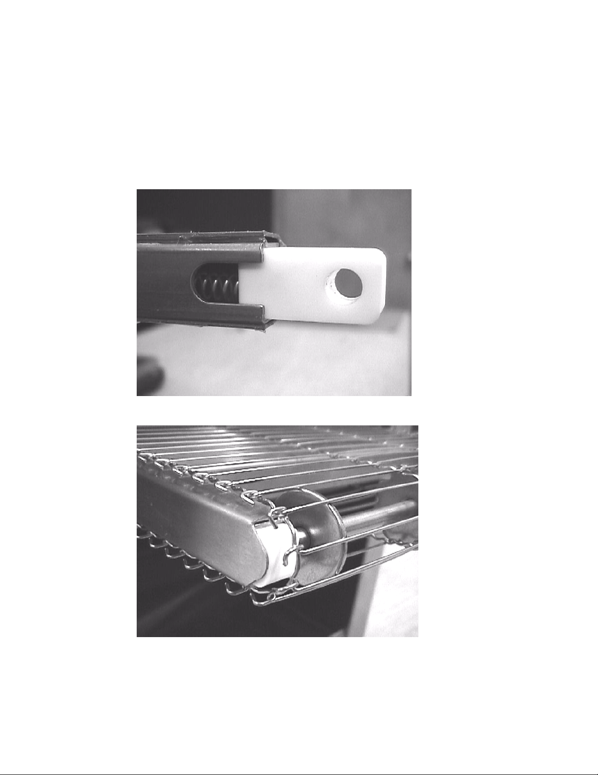
SPRING LOADED FRONT BEARING ASSEMBLY
Your Holman Conveyor Toaster is equipped with a spring-loaded front bearing assembly
as shown below in fig. 1. The spring-loaded bearing assembly keeps the conveyor belt
at a constant tension as the unit heats up and cools down. The conveyor belt is set to
the proper tension when the white Teflon bushing is flush with the end of the extension
as shown in fig. 2.
Fig. 1
Fig. 2
Page 1a
REVISED 06/05/00 MJC
BF700DOC.
Page 4
HOLMAN CONVEYOR TOASTERS
COOKING PROCEDURES
A. PRODUCT TOASTING
SPEED CONTROL
POWER SAVER
OPERATOR'S MANUAL
MODEL BF700
BAGEL
TURBO TOAST
FAST
D
L
A
I
R
G
K
J
E
T
R
E
R
CONVEYOR SPEED
E
N
OFF
E
S
R
T
F
G
A
U
Y
N
L
D
L
S
B
A
Y
OFF
V
E
R
1. Turn the rotary power saver switch to the full power position.
2. Allow warm up time of 5 to 10 minutes.
3. Test with a bagel half.
a. If toasting is too light, turn conveyor speed control counterclockwise to a
slower speed.
b. If toasting is too dark, conveyor speed control clockwise to a faster
speed.
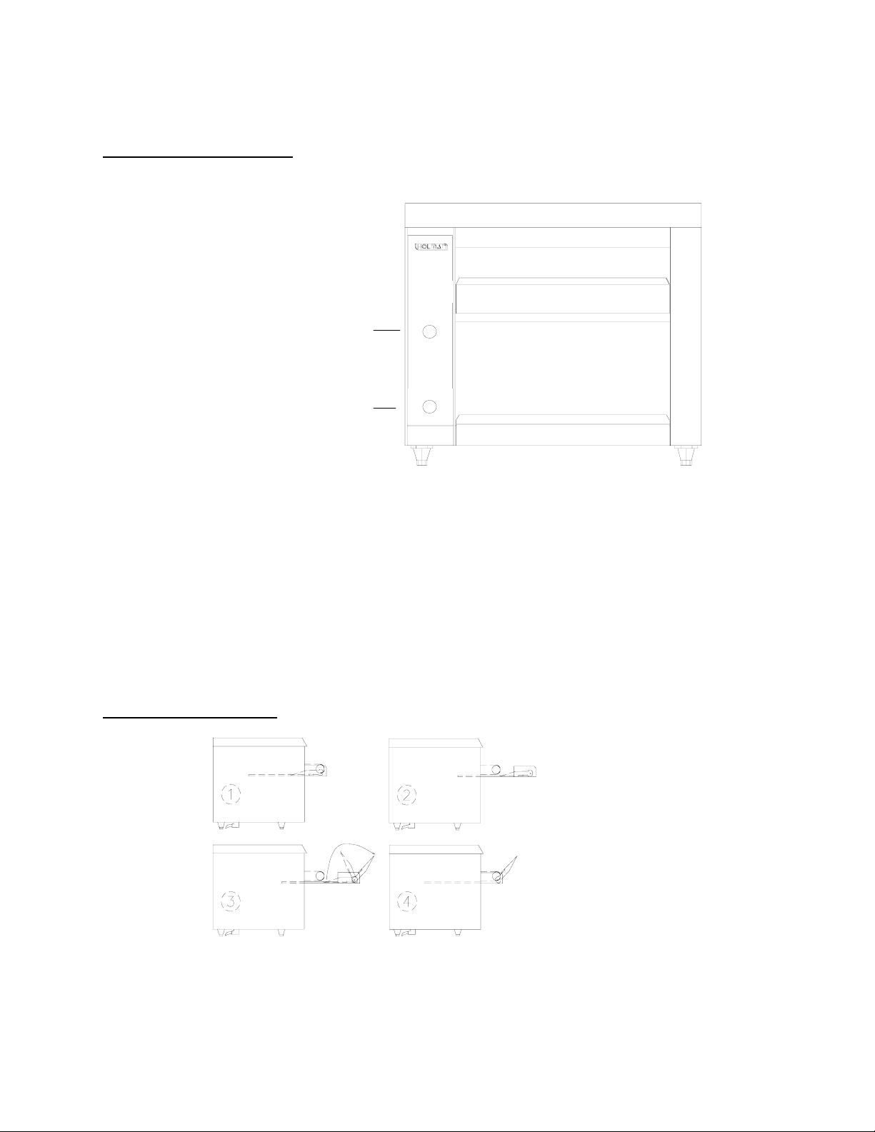
OPTIONAL FEED TRAY
1). Optional Feed Tray is Stored
Inside Of Crumb Tray.
2). Slide Crumb Tray out To
Expose Feed Tray.
3). Flip Feed Tray Into
Position.
4). Slide Crumb Tray Back Into
Unit Before Operation.
REVISED 06/05/00 MJC
BF700DOC.
Page 2
Page 5
OPERATOR'S MANUAL
HOLMAN CONVEYOR TOASTERS
MODEL BF700
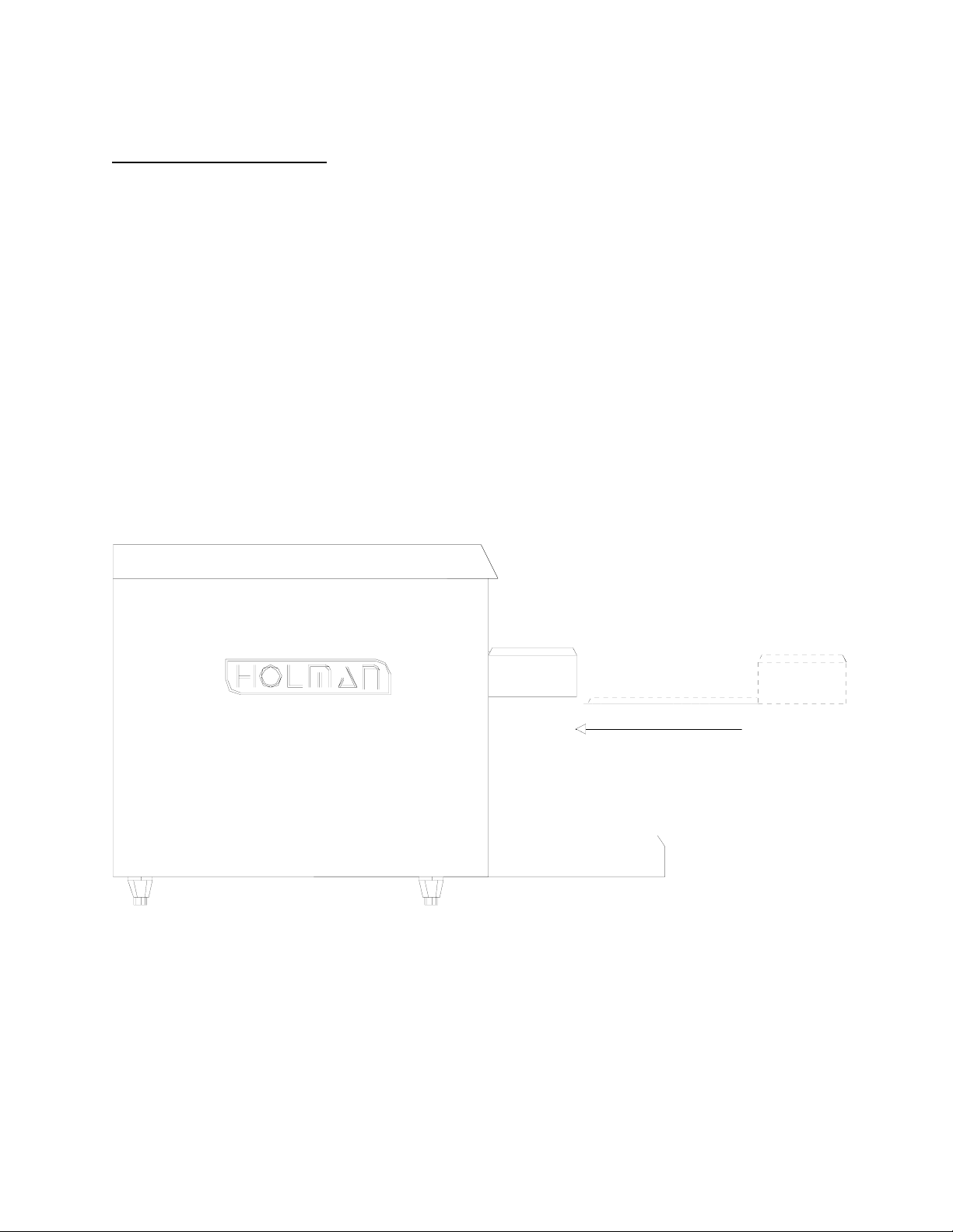
CLEANING PROCEDURES
1. Clean air intake on bottom of unit.
2. For lightly soiled conveyor belts, turn conveyor speed control to fastest
setting and wipe with a damp cloth. For heavily soiled conveyors, turn conveyor
speed control to fastest setting and wipe with a light abrasive pad.
3. Turn main power switch to the OFF position.
4. After the unit cools, remove interior crumb tray (as shown below) and clean.
Slide crumb tray back into position. DO NOT OPERATE UNIT WITHOUT
CRUMB TRAY IN PLACE AS THIS CAUSES OVERHEATING IN THE
CONTROL BOX
5. Wipe exterior surface of unit.
CRUMB TRAY
SLIDES BENEATH
CONVEYOR BELT
NOTE:
PERIODIC MAINTENANCE. CALL HOLMAN FACTORY SERVICE DEPARTMENT FOR DETAILS.
LUBRICATION OF DRIVE CHAIN WITH A GRAPHITE BASED LUBRICANT IS REQUIRED AS
REVISED 06/05/00 MJC
Page 3
BF700DOC.
Page 6
OPERATOR'S MANUAL
HOLMAN CONVEYOR TOASTERS
MODEL BF700
TROUBLESHOOTING GUIDE
UNIT WILL NOT HEAT, CONVEYOR BELT WILL NOT MOVE.
1. Make sure air intake on bottom of unit is clean.
2. Be sure the main circuit breaker is switched to the
ON position.
3. Check to see if the toaster is plugged in and all controls are turned to the
ON position.
B.
1. Call Holman Factory Service Department at
may need replacing.
C.
1. DISCONNECT UNIT FROM POWER SOURCE.
2. Remove screws (2 ea.) holding top cover in place at the rear of the unit.
3. Remove top cover (see page 10).
4. Remove each screw holding side panels in place and lift them up and out.
5. Loosen the four screws which hold the drive motor in place.
UNIT HAS HEAT ONLY ON ONE SIDE, CONVEYOR BELT TURNS FREELY.
1-800-225-3958 as heating element
CONVEYOR BELT DOES NOT TURN, HEATER TUBES GET HOT.
To check for mechanical binding:
6. Slide the motor up allowing the drive chain to be removed from the
sprockets.
7. Move the conveyor belt by hand to check for mechanical binding. If
conveyor moves freely, call the Holman Factory Service Department at
1-800-225-3958 as the drive motor and/or speed control may need
replacing.
8. Refer to page 10 for top cover reinstallation.
DRIVEN SPROCKET
REAR BEARING
DRIVE CHAIN
DRIVE MOTOR
DRIVE SPROCKET
Page 4
REV 06/05/00 MJC
BF700DOC.
Page 7

OPERATOR'S MANUAL
HOLMAN CONVEYOR TOASTERS
MODEL BF700
TROUBLE SHOOTING GUIDE (CON'T)
D. CONVEYOR BELT RUNS AT ONE SPEED REGARDLESS OF SPEED
CONTROL SETTING.
1. Call Holman Factory Service Department at
1-800-225-3958 as speed
control should be replaced.
E.
UNIT WILL NOT HEAT, CONVEYOR BELT MOVES PROPERLY.
position.
1. Check to see if the Power Saver Switch has been turned to the FULL POWER
2. Push heat limit switch on front of control box as shown below.
If this reactivates the heater tubes, see HEAT LIMIT SWITCH in
the following section.
HEAT LIMIT SWITCH
Your Bagel Fast conveyor toaster is equipped with an automatically activated
Heat Limit Switch which interrupts the heater tube connections if the ambient
temperature in the control box exceeds 190F (88C). This heat limit switch
can be reset manually by pushing the red button on the bottom left of the unit as
shown below.
NOTE: Air intake must be free of obstructions.
HIGH LIMIT/RESET
POWER SUPPLY
CORD HOLE
BOTTOM VIEW OF UNIT
Page 5
LEG
AIR INTAKE
REV. 06/05/00 MJC
BF700DOC.
Page 8

OPERATOR'S MANUAL
HOLMAN CONVEYOR TOASTERS
MODELBF700
MAINTENANCE PROCEDURES
A. CONVEYOR BELT AND DRIVE MOTOR DO NOT REQUIRE LUBRICATION.
B. REPLACING HEATER TUBES (as below)
1. DISCONNECT UNIT FROM POWER SOURCE.
2. Remove top cover (see page 10).
3. Remove each screw holding side panels in place and lift them up and out.
4. Remove heater tube wire from terminal block connection, keeping
top and bottom wires separate.
5. Remove heater tube retainers by removing retaining screws with washer.
6. Gently,
7. Gently,
tube came out through.
pull defective heater tube out of unit.
guide the new heater tube through the same hole the defective heater
8. Replace heater tube retainers, reconnect heater tube wires to terminal
block and install side panels.
9. Refer to page 10 for reinstallation of top cover.
Page 6
REV. 06/05/00 MJC
BF700.DOC
Page 9

OPERATOR'S MANUAL
HOLMAN CONVEYOR TOASTERS
MODEL BF700
MAINTENANCE PROCEDURES (CON'T)
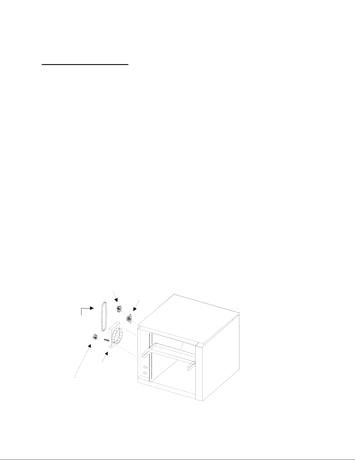
C. REPLACING CONVEYOR BELT DRIVE MOTOR
1. DISCONNECT UNIT FROM POWER SOURCE.
2. Remove screws (2ea.) holding top cover in place at the rear of the unit.
3. Remove top cover (see page 10).
4. Remove each screw holding side panels in place and lift them up and out.
5. Remove sprocket from motor shaft.
6. Remove the wire from terminal block connecting the drive motor to
internal wiring.
7. Remove screws holding motor in place.
8. Put new motor in place and attach loosely with mounting screws.
9. Replace sprocket on motor shaft.
10. Slide motor until the drive chain has about 1/8" slack when lightly pushed
at the center of its top open run.
11. Tighten screws to secure motor.
12. Rewire leads same as removed in step 5.
13. Replace side panel and control box cover.
14. Replace top cover (see page 10).
IF ASSISTANCE IS REQUIRED FOR THIS OR ANY OTHER PROCEDURE IN THIS
MANUAL CALL HOLMAN FACTORY SERVICE DEPARTMENT AT
1-800-225-3958.
24 HOURS/DAY 7 DAYS/WEEK
DRIVEN SPROCKET
REAR BEARING
DRIVE CHAIN
DRIVE MOTOR
DRIVE SPROCKET
LUBRICATION OF DRIVE CHAIN WITH A GRAPHITE BASED LUBRICANT IS REQUIRED AS
PERIODIC MAINTENANCE. CALL HOLMAN FACTORY SERVICE DEPARTMENT FOR DETAILS.
Page 7
REV. 06/05/00 MJC
BF700DOC.
Page 10

OPERATOR'S MANUAL
HOLMAN CONVEYOR TOASTERS
TURBOTOAST SERIES
INSTRUCTIONS FOR REINSTALLING THE TOP COVER
POSITION THE TOP COVER AS SHOWN
ALIGN THE LIP OF THE TOP
COVER UNDER THE SLOT IN
FRONT OF UNIT
SLIDE COVER TOWARD BACK OF UNIT
AS FAR AS POSSIBLE
LOWER THE REAR OF THE TOP COVER DOWN OVER THE BACK
OF THE UNIT AND SECURE WITH THE SCREWS PROVIDED.
REV. 06/05/00 MJC
BF700.DOC
PAGE 10
Page 11

Star
Manufacturing
International Inc.
10 Sunnen Dr.
St. Louis, MO 63143
Phone: (314) 781-2777
FAX: (314) 781-2714
CONVEYOR BELT REMOVAL PROCEDURES
For units without Master Links
1) Turn off unit and allow to cool.
2) WARNING - DISCONNECT UNIT FROM POWER
SUPPLY OR TURN OFF AT WALL BREAKER
BEFORE PROCEEDING TO NEXT STEP.
3) Remove unload tray by unscrewing the two thumb
screws on either side of the exit tray. Lift the tray
up and away from the oven. Remove the Load Up
and Unload Trays. (Fig. 1)
Service Kit
Instructions
4) Remove Crumb Trays, Burn Guards & load-up
trays.
5) Standing at the end on the unit, pick-up the
conveyor belt and un-hook one end.
Page 12

6) Trace that link down to the other end and unhook
from the opposite side.
7) Using both hands, bring both ends together and
push the link forward to disengage it from the belt.
8) Re-hook the loose ends back onto the previous link,
to prevent the link from being damaged or bent.
9) Now that the link have been un-hooked, the Conveyor can now be carefully removed from the oven.
Standing at the end of the oven. Starting with the
end on bottom, roll the conveyor belt until it has
been totally removed from the oven. Take careful
notice being sure not to damage the heater tubes.
NOTE: DO NOT ATTEMPT TO CLEAN THE HEATER
TUBES.
Page 13

10) For heavy soiled Conveyor Belt, soak over night in
hot soapy water.
11) Take this opportunity to clean and remove any
loose materials the inside of the unit. Using a mild
cleaner and damp cloth, carefully wipe the inside
surfaces being sure NOT to clean the heater tubes.
Damage can occur to the HEATER tubes from
improper cleaning.
DO NOT SPRAY CLEANING SOLUTIONS INTO
OVEN CAVITY.
12) Reinstall Conveyor Belt by fi rst laying the belt along
bottom of oven cavity making sure the hooks on
the sides of the belt will be facing the inside and
the ends of the hooks will be pointing away from
the direction of belt so not to catch on any internal
components once put back into operation.
NOTE: THE DIRECTION OF THE BELT.
13) Next, pull one end of Conveyor Belt over the top
of the sprockets, (being sure to line the links up
properly with the sprockets) bringing the two ends
together.
14) Un-hook both sides of the last link on the Conveyor.
Page 14

15) Bring the two ends together and thread them
through the middle section of the opposite end of
the belt, using both hands.
16) Re-hook the two ends of the Conveyor, once again
completing the Conveyor Belt system.
17) Examine the oven to assure proper installation,
once satisfi ed, reinstall burn guard, crumb tray and
load-up trays.
18) Reconnect oven to power supply and check for
proper operation.
IF ASSISTANCE IS REQUIRED, CALL THE STAR
SERVICE TEAM AT 1-800-807-9054
Page 15

Page 16

Page 17

OPERATOR'S MANUAL
HOLMAN CONVEYOR TOASTERS
WIRING DIAGRAM
MODEL BF700
TOP HEAT
BOTTOM HEAT
GROUND
POWER SUPPLY
CORD
FAN SWITCH
L2
FAN MOTOR
DRIVE
MOTOR
PLUG CONFIGURATION
BLUE:
220/240 VAC
WHITE: 208 VAC
NEMA 6-20P
BLACK: COMMON
L1
POWER SAVER
RESET/HIGH LIMIT
4
2
3
1
SPEED
CONTROL
208/240 VOLT
HEATER TUBES
TOP VOLTAGE WATTAGE BOTTOM VOLTAGE WATTAGE
197841 208 700 197896 208 200
197844 220 700 197874 220 200
197842 240 700 197872 240 200
BF700DOC. REV. 06/05/00 MJC
PAGE 9
Page 18

Page 19

Model: BF700 Conveyor Toaster
Page 20

BF700 (GEN 1 before 11/99 & GEN 2 after 11/99)
KEY # PART # QTY. DESCRIPTION GEN1/2
1
2
2a HQ-402375 1 RIGHT SIDE PANEL
2a HQ-402376 1 LEFT SIDE PANEL
3 HP-401816 1 SLIDE OUT TRAY/TOAST CHUTE EXTENSION
4
5 2B-200763 1 LOAD-UP TRAY
6 SEE BELOW FOR HEATER TUBES
7
8 SP-160025 1 CONVEYOR BELT (10” X 41”)
9 2U-200504 1 DRIVE MOTOR (REVERSED)
10 2P-200648 1 DRIVE SPROCKET (25BB32 X 5/16”)
11 2P-200645 1 DRIVEN SPROCKET (25B17 X 5/16”)
12
13
14
15 HA-112261 2 BUSHING 5/16”
16 2U-200561 1 FAN MOTOR
17 2R-200562 1 FAN GUARD
18 2R-200709 4 LEG, 1” CHROME PLASTIC
19 PS-120319 1 SERVICE KIT ROTARY SWITCH
20 SP-115360 2 CONTROL PANEL KNOB
- - 2M-200883 LABEL-BAGEL FAST
21 SP-118002 1 SPEED CONTROL (250W)
22 2E-200566 1 HIGH LIMIT RESET SWITCH
NI 2E-200574 1 FAN SWITCH
NI 2K-Y3240 1 CORD BUSHING
NI HG-140024 1 POWER SUPPLY CORD
NI HQ-115152 1 RETROFIT PANEL KIT
NI 2P-200736 2 BEARING SPRING (2”) GEN2
6a HO-197841 4 208V TOP (15.5Ω, 703W, 6.7A) (UNIT=14.6A) GEN1
6b HQ-198025 2 208V BOTTOM (50.8Ω, 200W, 1.0A) (UNIT=14.6A) GEN1
6a HQ-197873 4 220V TOP (19.2Ω, 700W, 5.4A) (UNIT = 14.5A) GEN1
6b HQ-197874 2 220V BOTTOM (56.9Ω, 200W, 1.82A) (UNIT = 14.5A) GEN1
6a HO-197842 4 240V TOP (19.2Ω, 707W, 5.9A) (UNIT = 13.0A) GEN1
6b HQ-197872 2 240V BOTTOM (67.7Ω, 200W, 1.0A) (UNIT=13.0A) GEN1
HP-100959
HQ-100989 GEN2
HP-401808
HQ-402373 GEN2
HP-401810
HQ-101091 CRUMB TRAY (DD special )
GA-402128
HQ-402272 GEN2
ZZ-150010 1 DRIVE CHAIN 21-1/4” GEN1
HM-150025 1 DRIVE CHAIN 22-1/2” GEN2
2P-200693
2P-200700 IDLER BUSHING (SPRING LOADED) GEN2
2A-202900
2A-202904 IDLER SHAFT
1 TOP COVER
1 BACK COVER
CRUMB TRAY
1
2 HEATER TUBE RETAINER
IDLER BUSHING GEN1
2
DRIVE SHAFT
1
QUARTZ HEATER TUBES
GEN1
GEN1
GEN1
6a HQ-198027 4 208V TOP (15.8Ω, 645W, 6.2A) (UNIT=14.9A) GEN2
6b HQ-198025 2 208V BOTTOM (53.88Ω, 200W, 1.9A) (UNIT=14.9A) GEN2
6a HQ-197873 4 220V TOP (19.2Ω, 600W, 5.4A) (UNIT = 14.5A) GEN2
6b HQ-197874 2 220V BOTTOM (56.9Ω, 200W, 1.82A) (UNIT = 14.5A) GEN2
6a HQ-198034 4 240V TOP (20.2Ω, 675W, 5.6A) (UNIT = 13.0A) GEN2
6b HQ-198033 2 240V BOTTOM (67.7Ω, 200W, 1.67A) (UNIT=13.0A) GEN2
METAL HEATERS
6a 2N-209131 4 208V TOP (600W)
2N-209198 4 208V BOTTOM (200W)
2N-209132 4 240V TOP (600W)
2N-209194 4 240V BOTTOM (200W)
 Loading...