

Page 1

DOT MA TRIX PRINTER
AR-1000
TECHNICAL MANUAL
[
SECOND EDITION
]
Page 2

NOTICE
• All rights reserved. Reproduction of any part of this manual in any
form whatsoever, without STAR’s express permission is forbidden.
• The contents of this manual are subject to change without notice.
• All efforts have been made to ensure the accuracy of the contents
of this manual at the time of going to press. However, should any
errors be detected, STAR would greatly appreciate being informed of them.
• The above notwithstanding, STAR can assume no responsibility
for any errors in this manual.
© Copyright 1997 Star Micronics Co.,Ltd.
Page 3

INTRODUCTION
This manual describes the AR-1000 dot matrix printer.
It is designed for use as a reference for periodic inspections and maintenance procedures to be executed
by service personal. It is not intended for the general user. Users of this manual should have a basic
knowledge and understanding of the English language.
•
This manual is divided into the following sections:
Chapter 1 General Specifications
Chapter 2 Adjustments
Chapter 3 Parts Replacement
Chapter 4 Maintenance and Lubrication
Chapter 5 Parts List
•
First edtion : Oct.1997
Second edtion : Aug.1998
1
5
2
3
4
Page 4

(Blank Page)
Page 5

CHAPTER 1
GENERAL SPECIFICATIONS
1. General Specifications ............................................................................................3
2. External Appearance and Composition.................................................................5
3. Parallel Interface ......................................................................................................7
3-1. General Specifications ..................................................................................7
3-2. Connector Signals .........................................................................................7
4. Serial Interface .........................................................................................................8
4-1. General Specifications ..................................................................................8
4-2. Connector Signals and Functional Descriptions ........................................8
5. Block Diagram.......................................................................................................... 9
1
Page 6

(Blank Page)
Page 7

– 3 –
1. General Specifications
Printing System Serial Impact Dot-Matrix
Printing Speed Pitch Draft (cps/dpi) LQ (cps/dpi)
Pica (10 cpi) 250/120H 83/360H
Elite (12 cpi) 300/120H 100/360H
Semi-condensed (15 cpi) 375/120H 125/360H
Condensed pica (17.1 cpi) – 143/360H
18 cpi 300/180H –
Condensed elite (20 cpi) 250/240H 167/360H
H: half-dot
Print Direction Draft: Bi-directional/Uni-directional logic seeking
(Selectable by Command)
LQ: Bi-directional/Uni-directional logic seeking
(Selectable by Command)
Bit-Image: Bi-directional/Uni-directional logic seeking
(Selectable by Command)
Print Head Number of pins: 24
Life: 200 million dots/pin (Normal Mode)
100 million dots/pin (Multi Part Mode)
Line Spacing 1/6″, 1/8″
n/60″, n/180″, n/216″,n/240″, n/360″: software
Environment Operating temperature: 41˚F to 95˚F (5˚C to 35˚C)
Storage temperature: -22˚F to 149˚F (-30˚C to 65˚C)
Operating humidity: 30% to 80% (noncondensing)
Storage humidity: 20% to 90% (noncondensing)
Paper Cut-sheet
Paper width: 3.0″ to 8.3″ / 76.2 to 210 mm
Paper length: 2.5″ to 11.7″ / 63.5 to 297 mm
Paper weight (1-ply): 14 to 42 lbs / 52 to 156 g/m2 / 45 to 135 kg
Multi-part: 11 to 14 lbs / 40 to 52 g/m2 / 34 to 45 kg; pressure
sensitive paper. Total thickness: 0.014″/0.35mm
Page 8
– 4 –
Pass-Book
Paper width: 4″ to 6″ / 101.6 to 152.4 mm
Paper length: 5.0 - 8.0” / 127.0 - 203.2 mm(With the Pass-book opening.)
Paper thickness: Max 2.0mm (Total thickness)
Paper number: Max 14 (Except cover)
Interface Standard: RS-232C serial
Option: Centronics parallel or RS-232C serial
Ribbon Type On-carriage, dedicated
Monochrome: Black only
Ribbon Life P24: 2million characters (ASCII Draft)
Power Supply 220V AC +15%/-15%, 50Hz
Power Consumption 13W during stand-by
55W during ASCII draft printing
Options IS-NP192 Serial interface unit
IS-NPC Parallel interface unit
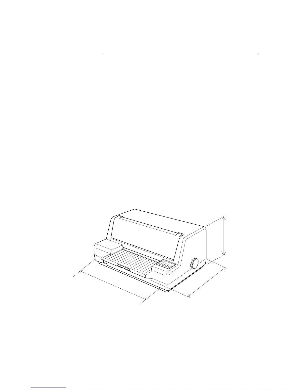
Fig. 1-1 External Dimensions
320mm
12.6"
410mm
16.1"
194.5mm
7.66"
Weight 18.94 lbs/8.6kg
Page 9
– 5 –
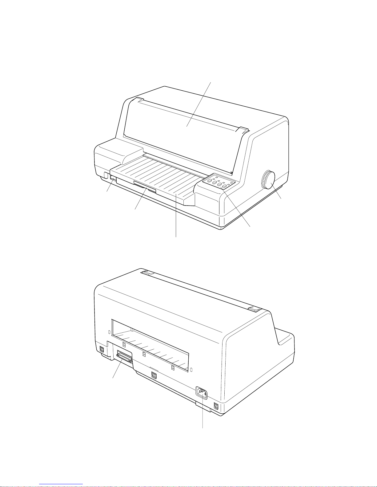
2. External Appearance and Composition
Fig. 1-3 Rear View of the Printer
Fig. 1-2 Front View of the Printer
Front cover
Platen knob
Control panel
Power switch
Document table
Document
table
extension
Power terminal
Serial interface
connector
Page 10
– 6 –
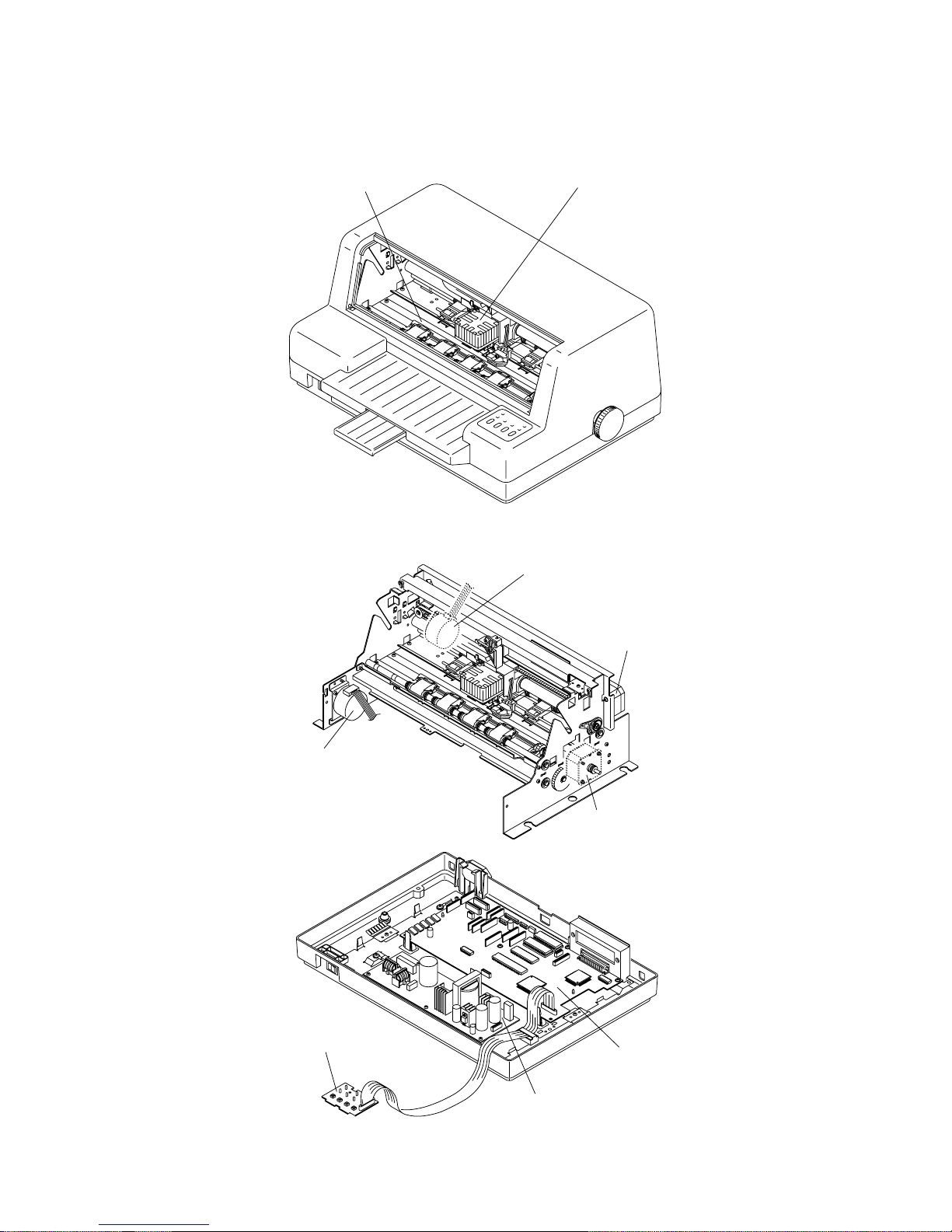
Fig. 1-4 Print Cover Removed
Fig. 1-5 Diagram of Internal Layout
Platen
Print Head
Gap Motor
Carriage Motor
Paper Feed Motor
Shutter Motor
Main Logic Board
Power Supply Unit
Control Panel Board
Page 11
– 7 –
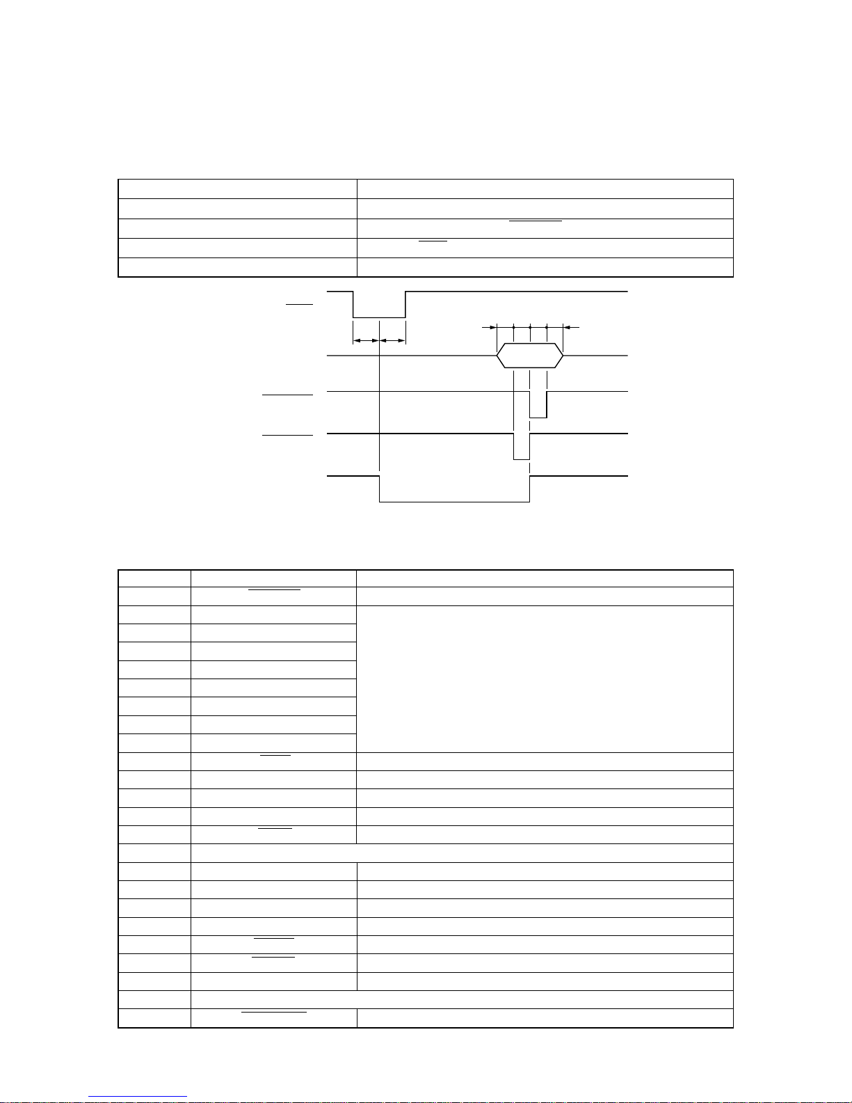
Fig. 1-6 Timing Charts for Parallel Interface
ACK
Data
STROBE
(EDS B-6 : ON)
STROBE
(EDS B-6 : OFF)
BUSY
5µs
t : More than 0.5µs
5µs
tttt
3. Parallel Interface
3-1. General Specifications
Item Specifications
Interface Centronics-compatible
Synchronization System Via externally supplied STROBE pulse
I/F Protocol Using ACK and BUSY signals
Logic Level Compatible with TTL level
Pin Name Function
1 STROBE Goes low for ≥ 0.5µs when active.
2 DATA0
3 DATA1
4 DATA2
5 DATA3
6 DATA4
7 DATA5
8 DATA6
9 DATA7
10 ACK 10µs low to acknowledge receipt of data.
11 BUSY Printer sets line low when ready to receive data.
12 PAPER High when paper runs out.
13 SELECT High when printer is on-line.
14 AFXT Printer ignores this signal.
15 Not used.
16 SIGNAL GND Signal ground
17 CHASSIS Chassis ground (isolated from signal ground)
18 +5V +5V DC output from printer
19~30 GND Twisted pair ground return
31 RESET Printer is reset when this signal goes low.
32 ERROR Low when printing cannot continue due to error.
33 EXT GND External ground
34~35 Not used
36 SELECT IN Printer ignores this signal.
3-2. Connector Signals
These signals represent information for the 1st through 8th bit of
parallel data, respectively. Each signal is HIGH when data is logical
1, and LOW when logical 0.
Page 12
– 8 –
4 Serial Interface
4-2. Connector Signals and Functional Descriptions
4-1. General Specifications
Item Specifications
Interface RS-232C level
Synchronization System Asynchronous
Baud rate
300 - 19,200 bits per second (BPS) [selectable]
300, 600, 1200, 2400, 4800, 9600, 19200 BPS
Word length
Start bit: 1 bit
Data bit: 7 or 8 bits (selectable)
Parity bit: Odd, Even or None (selectable)
Stop bit: More than 1 bit length
Signal polarity
Mark: Logic ″1″ (–3V to –15V)
Space: Logic ″0″ (+3V to +15V)
Handshaking
DTR
XON/XOFF
Pin No. Signal name Direction Function
1 F-GND — Printer chassis ground.
2 TXD OUT This pin carries data from the printer
3 RXD IN This pin carries data to the printer.
4 RTS OUT Always space.
5 CTS —
6 NC Unused.
7 S-GND — Signal ground.
8~10 NC Unused.
11 RCH OUT
12 NC Unused.
13 NC Unused. (Signal ground.)
14~19 NC Unused.
20 DTR OUT The printer sets this signal to space when it is ready to receive data.
21~25 NC Unused.
This signal is space when the computer is ready to send data.
The printer does not check this pin.
The printer sets this signal to space when it is ready to receive data.
This line carries the same signal as pin 20.
Page 13
– 9 –
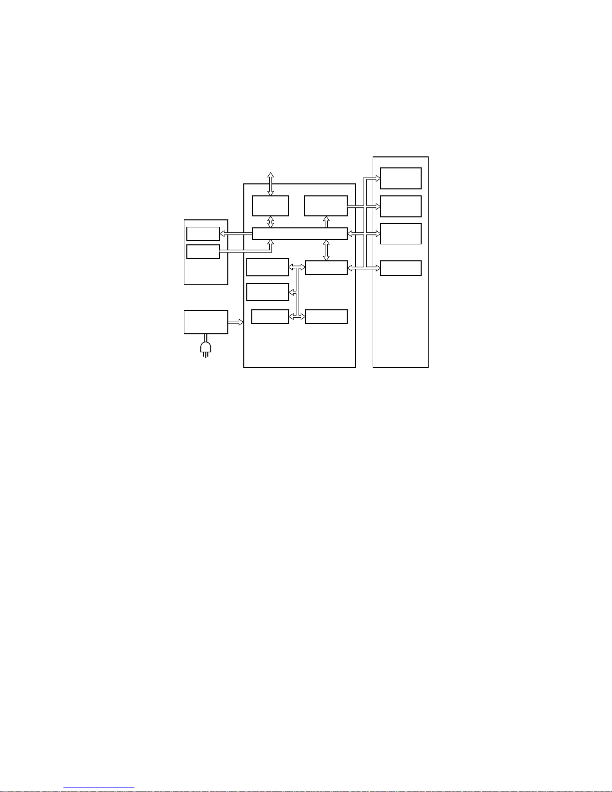
5 Block Diagram
The block diagram of this printer is shown in Fig. 1-7.
Data (From Host Computer)
LED
Switch
Control
panel board
Power
supply unit
AC Power
interface
Driver
Gate array
CPU
RAM
Masked ROM
8M
EE-PROM
Paper feed
motor
Carriage
motor
Print head
Main logic board
Printer
mechanism
Detectors
UVE-PROM
1M
Fig. 1-7 Block Diagram
Page 14

(Blank Page)
Page 15

CHAPTER 2
ADJUSTMENTS
This printer has undergone various adjustments so that it will attain a given standard of performance.
In this chapter, a brief explanation is given of the methods for making adjustments.
Follow the instructions when performing maintenance inspections or when replacing parts to correct malfunctions.
1. Adjustment of Gap Between Print Head and Platen........................................... 13
2. Adjustment of Timing Belt Tension......................................................................
14
2
Page 16

(Blank Page)
Page 17
– 13 –
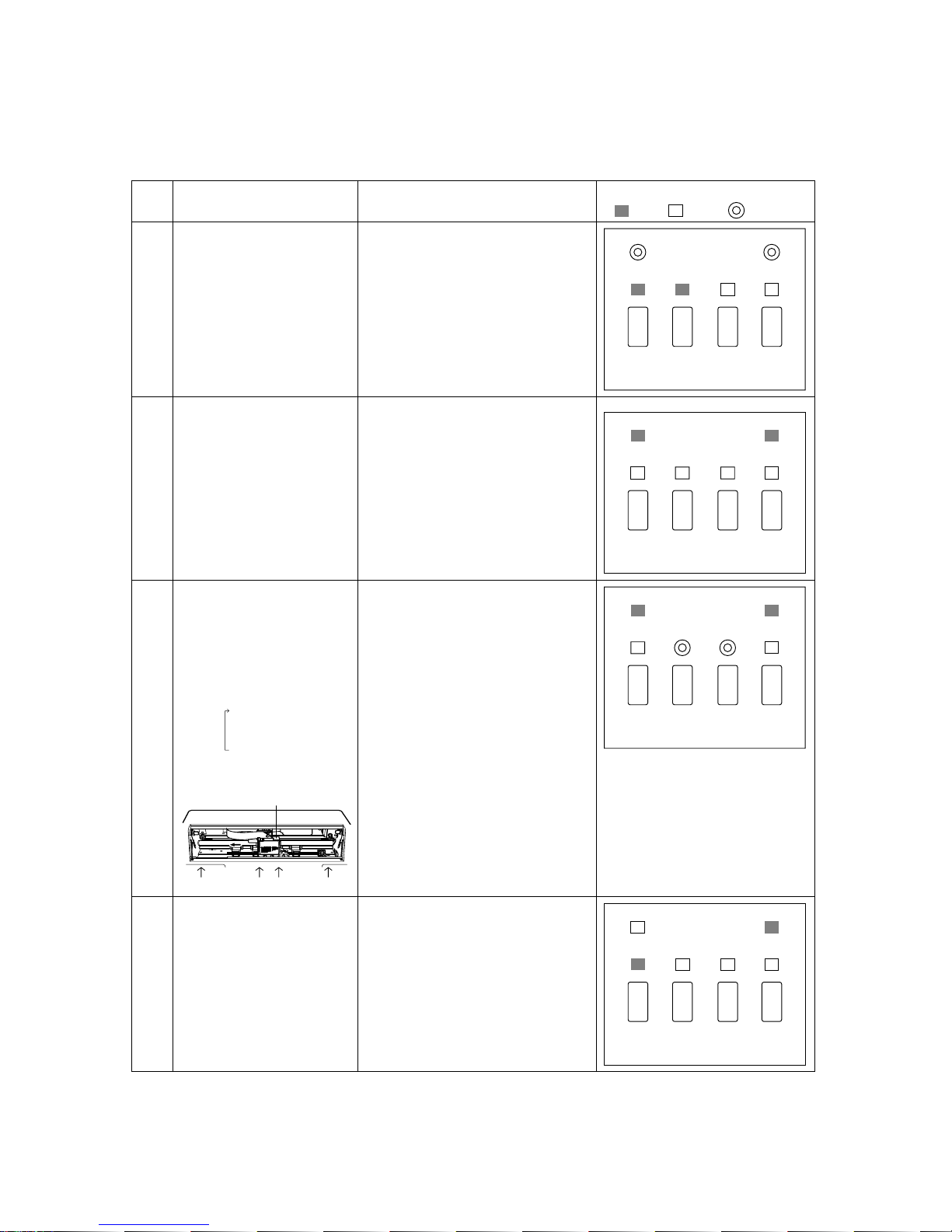
1. Adjustment of Gap Between Print Head and Platen
Procedures Printer Operations LED
:ON :OFF :Blinking
1
2
3
4
Power on the printer while
holding down the [SW3] and
[SW4] buttons.
5 Short beeps and enters the head gap
adjustment mode.
Insert paper of 55 Kg keeping
it to the most left.
Remove paper.
Loads paper authomatically,senses
paper thickness and ejects it backward
while keeping the current head
gap.(Insert paper again if ejected
forward.)
Paper needs to be removed.
Adjustment(1st position)
Press [SW2] to widen gap.
Press [SW3] to narrow gap.
Press [SW1] to move carriage.
+Area:[LED A] LED is blinking.
-Area:[LED B] LED is blinking.
<A,B,C>
Set head gap at A,B and C.
Head Gap : 0.39-0.47mm
<D>
Set card holder gap at D.
Standard : 0.16-0.30
Finish and memory
Press [SW4] button.
Memorizes head gap and exits from
the head gap adjustment mode.
LED BLED A
SW1
SW2
SW3
SW4
LED BLED A
SW1
SW2
SW3
SW4
LED BLED A
SW1
SW2
SW3
SW4
LED BLED A
SW1
SW2
SW3
SW4
A. Left
B. Right
C. Center
D. Right of center
Carriage
ACDB
Page 18
– 14 –
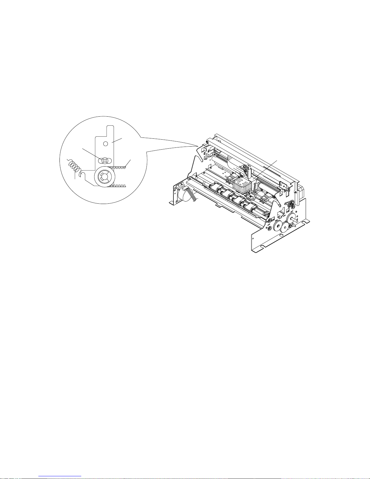
2. Adjustment of Timing Belt Tension
(1) Remove the front case unit according to the procedures described in chapter 3.
(2) Move the carriage unit [1] up to the extreme right position.
(3) Move the screw [3] fixing tension lever assembly [2] approximately 1mm to loosen the tension, then tighten the
screw.
The timing belt tension [4] is determined by the spring [5].
Fig 2-1 Adjustment of Timing Belt Tension
[1]
[2]
[4]
[3]
[5]
Page 19

CHAPTER 3
PARTS REPLACEMENT
This chapter explains disassembly and reassembly of the printer. Note the following regarding disassembly and
reassembly.
1. Disconnect the printer from the wall outlet before servicing it.
2. Assembly is the reverse of disassembly unless otherwise specified.
3. After reassembly, coat the screw heads with locking sealant.
4. Lubrication information is not provided in this chapter. Refer to section 2 in chapter 4.
1. Upper Case Unit .....................................................................................................16
2. Printer Mechanism ................................................................................................. 16
3. Main Logic Board Unit ........................................................................................... 17
4. Power Supply Unit ................................................................................................. 17
5. Print Head ...............................................................................................................18
6. Carriage Unit ..........................................................................................................18
7. Carriage Motor Assembly .....................................................................................19
8. Shutter Motor Assembly........................................................................................19
9. Roller Guide Shaft A Assembly ............................................................................20
10. Roller Guide Shaft C Unit...................................................................................... 20
11. Shutter Assembly...................................................................................................21
3
Page 20
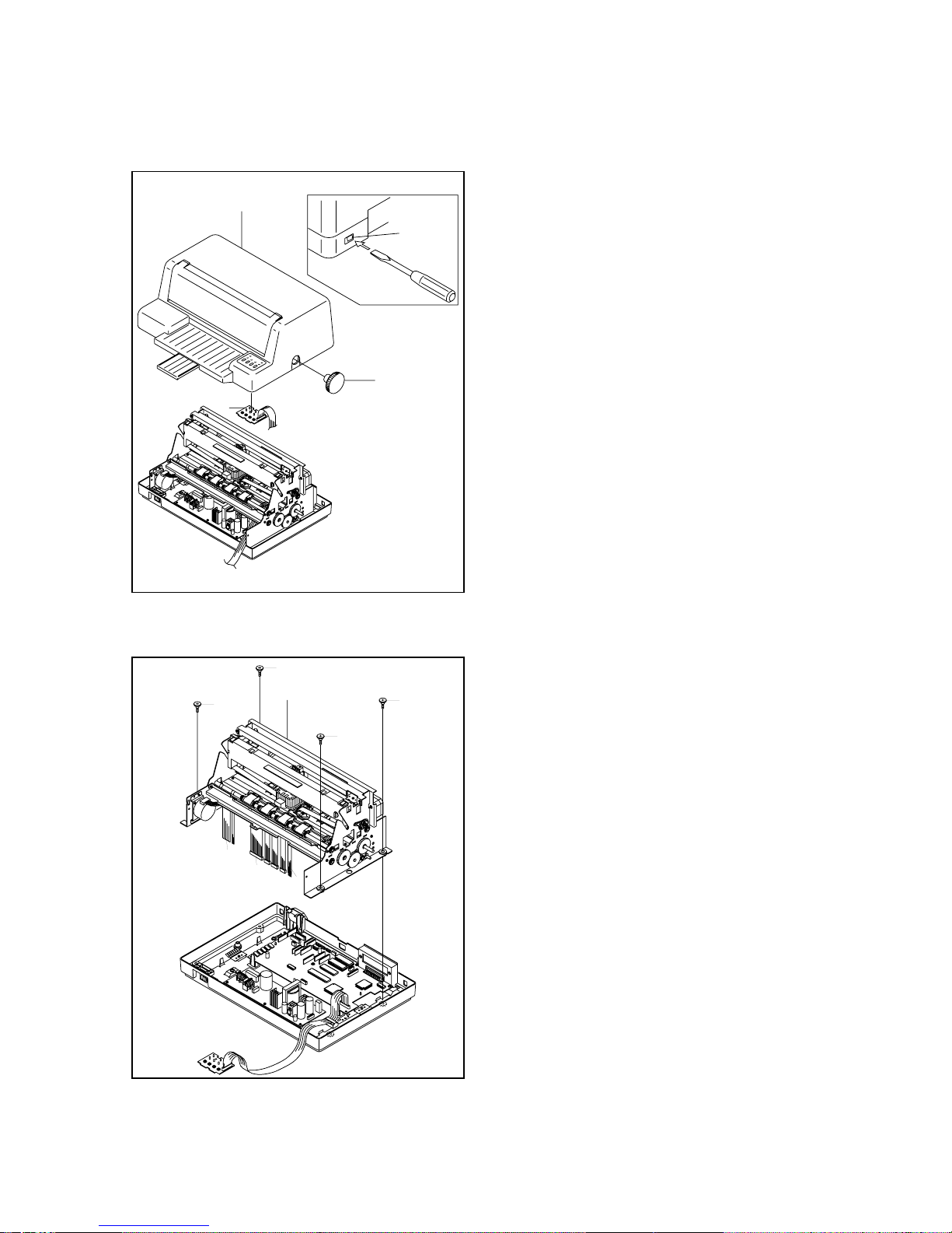
– 16 –
(1) Turn off the power switch.
(2) Remove the power cord from the AC output socket.
(3) Remove
• Platen knob [1]
• Upper case unit [2]
Detach the three hooks[2-1] of the upper case
unit, and lean the upper case forward for removal.
• Control panel board [3]
Detach the two hooks.
1. Upper Case Unit
2. Printer Mechanism
[2-1]
[2]
[1]
[3]
[1]
[1]
[1]
[4]
[3]
[2]
[3]
[1]
(1) Remove
Upper case unit as described in section 1.
• Four screws [1]
• Four connectors [2]
• Four cables [3]
• Printer machanism [4]
Page 21

– 17 –
(1) Remove
Printer machanism as described in section 2.
• Three screws [1]
• Connector [2]
• Main logic board unit [3]
(2) Adjust
• Gap between print head and platen. Refer to
section 1 of chapter 2.
3. Main Logic Board Unit
4. Power Supply Unit
(1) Remove
Printer machanism as described in section 2.
• Screw [1]
• Six screws [2]
• Screw [3]
• Swith holder [4]
Detach the two hooks.
• Power supply unit [5]
Detach the two hooks.
[3]
[1]
[4]
[2]
[5]
[2]
[3]
[1]
Page 22

– 18 –
(1) Remove
Upper case unit as described in section 1.
• Ribbon cassette [1]
• Move the carriage unit [2]to left side.
• Two screws [3]
• Two cables [4]
• Print head [5]
WARNING
• The Print head gets hot after printing .
Do not touch it untill in cools.
(2) Adjust
• Gap between print head and platen. Refer to se-
ction 1 of chapter 2.
5. Print Head
6. Carriage Unit
(1) Remove
Print head as described in section 5.
• Two screws [1]
• Rear angle [2]
• Spring [3]
• Screw [4]
• Tension lever unit [5]
• Two screws [6]
• Ribbon gear holder unit [7]
• Two flanged nuts [8]
• Gap adjust gear [9]
• Two bushings [10]
• Two screws [11]
• Two adjuster bushings [12]
• Carriage stay [13]
• Release lever [14]
• Cable holder [15]
• Head cable [16]
• Carriage unit [17]
[4]
[5]
[3]
[1]
[2]
[1]
[2]
[8]
[9]
[10]
[11]
[12]
[15]
[12]
[11]
[10]
[8]
[5]
[3]
[4]
[7]
[6]
[14]
[13]
[16]
[17]
Page 23

– 19 –
(1) Remove
Carriage unit as described in section 6.
• Connector [1]
• Two screws [2]
• Two rubber bushings [3]
• Rubber sheet [4]
• Carriage motor assy [5]
7. Carriage Motor Assembly
8. Shutter Motor Assembly
(1) Remove
Printer machanism as described in section 2.
• Connector [1]
• Two screws [2]
• Shutter motor assy [3]
[5]
[4]
[1]
[3]
[2]
[1]
[2]
[3]
Page 24

– 20 –
(1) Remove
Printer mechanism as described in section 2.
• Screw [1]
• Sub-roller guide [2]
• Two stop rings [3]
• Link plate [4]
• Stop ring [5]
• Stop ring [6]
• Screw [7]
• Link plate A [8]
• Link plate holder [9]
• Two bushings [10]
• Roller guide shaft A assy [11]
9. Roller Guide Shaft A Assembly
10. Roller Guide Shaft C Unit
(1) Remove
Carriage unit as described in section 6.
• Screw [1]
• Sub-roller guide [2]
• Two stop rings [3]
• Two bushings [4]
• Roller guide shaft C unit [5]
[6]
[9]
[2]
[1]
[11]
[4]
[3]
[3]
[7]
[9]
[10]
[5]
[8]
[5]
[1]
[2]
[4]
[3]
[4]
[3]
Page 25

– 21 –
(1) Remove
Printer mechanism as described in section 2.
• Two springs [1]
• Three stop rings [2]
• Link plate [3]
• Two stop rings [4]
• Screw [5]
• Link plate A [6]
• Shutter holder [7]
• Two bushings [8]
• Shutter assy [9]
11. Shutter Assembly
[8]
[2]
[9]
[1]
[1]
[8]
[7]
[4]
[6]
[4]
[3]
[2]
[2]
[5]
Page 26

(Blank Page)
Page 27

CHAPTER 4
MAINTENANCE AND LUBRICATION
1. Maintenance ...........................................................................................................25
1-1. Cleaning ........................................................................................................ 25
1-2. Checks ..........................................................................................................25
2. Lubrication ............................................................................................................. 26
2-1. Lubricant .......................................................................................................26
2-2. Lubricating Method ......................................................................................26
2-3. Lubricated Areas ..........................................................................................26
4
Page 28

(Blank Page)
Page 29

– 25 –
1. Maintenance
In order to maintain the optimum performance of this printer and to prevent trouble, maintenance must be carried out
according to the following items.
1-1. Cleaning
(1) Removal of dirt
Wipe off dirt with a soft cloth soaked in alcohol or benzine.
Note: Do not use thinner, trichlene or ketone solvents because they may damage plastic parts. Also during
cleaning, be careful not to moisten or damage electronic parts, wiring, or mechanical parts.
(2) Removal of dust, pile, etc.
Vacuum cleaning (with an electric cleaner) is preferred. Remove all dust, etc., inside the printer.
Note: After cleaning, check the oil level. If it is not adequate due to cleaning, replenish it.
1-2. Checks
Checks must be carried out at two levels: a “daily check” which the operator can easily carry out during operation, and
a “periodic check” which an expert should carry out.
(1) Daily check
When the printer is used on a daily basis, check that the printer is used properly. Make sure that the printer is
operating under the best conditions.
• Is any paper stuck in the paper box or printer case?
• Is the carridge ribbon set at the right position?
• Is there any foreign matter inside the printer? (Remove if any.)
• Is the print head getting excessively dirty?
(2) Periodic check
After 6 months or printing 1 million lines, the periodic check and lubrication must be carried out.
• Check for deformation of springs.
• Check the gap between the platen and the print head.
• Remove dust, dirt, etc., around the detectors.
Page 30

– 26 –
2. Lubrication
Lubrication is very important to maintain optimum performance and to prevent trouble.
2-1. Lubricant
The type of lubricant greatly affects the performance and durability of the printer, especially in a low temperature
environment. We recommend use of the grease and lubrication oils listed below for this printer
2-2. Lubricating Method
When lubrication is carried out in assembly and disassembly, wash parts well to remove dust and dirt before lubrication.
Lubrication must be carried out regularly once every 6 months or after 1 million lines have been printed. Lubrication is
necessary irrespective of the regular lubrication whenever lubricant becomes deficient after cleaning or whenever parts
have been disassembled or replaced.
2-3. Lubricated Areas
Type of oil Product name Maker
Grease MOLYKOTE EM-30L DOW CORNING ASIA LTD
Oil Mobil 1 (OW-40) Mobil oil Corporation
NO. LubricationProduct Name
[1] Rubbing surfaces of Bushing and PF roller A•B assembly EM - 30L
[2] Rubbing surfaces of Roller guide shaft and Bushing D•E EM - 30L
[3] Rubbing surfaces of Roller guide shaft A•C and Bushing D•E EM - 30L
[4] Rubbing surfaces of Sub roller shaft and Sub roller guide EM - 30L
[5] Rubbing surfaces of PF idler gear A•B and Shaft EM - 30L
[6] Rubbing surfaces of Shutter gear and Link plate EM - 30L
[7] Rubbing surfaces of Shutter holder and Link plate EM - 30L
[8] Rubbing surfaces of Gap adjust gear C and Shaft EM - 30L
[9] Rubbing surfaces of Gap motor pinion and Gap adjust gear C EM - 30L
[10] Rubbing surfaces of PF sub roller and Sub Roller holder B EM - 30L
[11] Rubbing surfaces of Shutter gear A shaft EM - 30L
[12] Rubbing surfaces of Shutter gear A and shaft EM - 30L
[13] Rubbing surfaces of Roller and Roller shaft EM - 30L
[14] Rubbing surfaces of Roller and Roller shaft EM - 30L
[15] Rubbing surfaces of Ribbon gear shaft B and Idler gear B EM - 30L
[16] Rubbing surfaces of Ribbon drive shaft and Bushing C EM - 30L
[17] Rubbing surfaces of Ribbon gear shaft B and Idler gear C EM - 30L
[18] Rubbing surfaces of Ribbon drive shaft and Bushing C EM - 30L
[19] Rubbing surfaces of Bushing B and Spring EM - 30L
[20] Rubbing surfaces of Bushing A and Spring EM - 30L
[21] Rubbing surfaces of Ribbon drive shaft and Ribbon drive gear EM - 30L
[22] Rubbing surfaces of Ribbon drive shaft and Idler gear A EM - 30L
[23] Rubbing surfaces of PF sub roller and Sub roller holder A EM - 30L
[24] Rubbing surfaces of Pulley shaft and TM pulley EM - 30L
[25] Rubbing surfaces of Pulley cap and Stop ring EM - 30L
[26] Rubbing surfaces of Carriage and Carriage stay OW - 40
Page 31

– 27 –
stop ring TM Pulley Pulley shaft
[25] [24]
[4]
[26]
[4]
[10]
[10]
[10]
[10]
[3]
[3]
[3]
[3]
[4]
[4]
[23]
[23]
[23]
[23]
[1]
[1]
[2]
[2]
Fig4-1 Luburicated Areas (Printer Mechanism2/1)
Page 32

– 28 –
A
A
B
B
[12]
Shutter gear A
Shaft
[11]
[1]
[3]
[6]
[1]
[1]
[3]
[2]
[5]
[7]
[7]
[2]
[8]
[3]
[9]
[1]
A
A
[3]
Fig4-2 Luburicated Areas (Printer Mechanism2/2)
Page 33

– 29 –
[17]
[15]
[18]
[18]
[19]
[19]
[20]
[20]
[21]
[21]
[22]
[16]
Fig4-4 Luburicated Areas (Ribbon Drive Unit)
Fig4-3 Luburicated Areas (Carriage Unit)
[14]
[13]
Page 34

(Blank Page)
Page 35

– 31 –
5
CHAPTER 5
PARTS LIST
HOW TO USE PARTS LIST
(1) DRWG. NO.
This column shows the drawing number of the illustration.
(2) REVISED EDITION MARK
This column shows a revision number.
Part that have been added in the revised edition are indicated with "#"
Part that have been abolished in the revised edition are indicated with "*" . For example,
#1 : First edition → Second edition *1 : First edition → Second edition.
(3) PARTS NO.
Parts numbers must be notified when ordering replacement parts. Parts described as “NPN” have no
parts number and are not in stock,i.e., unavailable.
(4) PARTS NAME
Parts names must be notified when ordering replacement parts.
(5) Q’TY
This column shows the number of the part used as indicated in the figure.
(6) REMARKS
Where there are differences in the specifications of the fuse,destinastions,etc.,the differences are described
in words or indicated by two letters
(7) RANK
Parts marked “S” are service parts. Service parts are recommended to be in stock for maintenance.
8. Control Panel Board ....................... 53
8-1. Circuit Diagram ............................53
8-2. Component Layout ......................53
8-3. Parts List ......................................53
9. Power Supply Unit .......................... 54
9-1. Circuit Diagram ............................54
9-2. Component Layout ......................55
9-3. Parts List ......................................56
10. Serial Interface Board IS-NP192
(Option) .........................................58
10-1. Circuit Diagram ............................58
10-2. Component Layout ......................58
10-3. Parts List ......................................58
11. Parallel Interface Board IP-NPC
(Option) .........................................59
11-1. Circuit Diagram ............................59
11-2. Component Layout ......................59
11-3. Parts List ......................................59
1. Printer Assembly ................................. 32
1-1. Disassembly Drawing ....................32
1-2. Parts List .........................................33
2. Printer Mechanism .............................. 34
2-1. Disassembly Drawing ...................34
2-2. Parts List ........................................35
3. Frame L Unit.......................................... 36
3-1. Disassembly Drawing ....................36
3-2. Parts List .........................................37
4. Frame R Unit ......................................... 38
4-1. Disassembly Drawing ....................38
4-2. Parts List .........................................39
5. Sub - Assembly .................................... 40
5-1. Lower Case Unit .............................40
5-2. Upper Case Unit .............................41
5-3. Carriage Unit...................................42
6. Wiring Scheme of Printer .................44
7. Main Logic Board
................................. 45
7-1. Circuit Diagram...............................45
7-2. Conponent Layout..........................48
7-3. Parts List .........................................49
Page 36

– 32 –
1. Printer Assembly
1-1. Disassembly Drawing
9
12
10
1
15
18
3
2
8
20
17
16
7
18
4
6
18
21
5
14
13
Page 37

– 33 –
1 89430410 PRINTER MECHANISM DP681 1
2 89164020 PRINT HEAD DP680 1
3 *1 86822170 MAIN LOGIC BD UNIT PBA-10 DS 1
#1 86822171 MAIN LOGIC BD UNIT PBA-10 DS 1
4 86823200 POWER SUPPLY UNIT PBA-10 DS 1
5 89597120 PARALLEL INTERFACE IP-NPC DS 1 OPTION
89597130 SERIAL INTERFACE IS-NP192 DS 1 OPTION
6 86821110 LOWER CASE UNIT PBA-10 DS 1
7 83912520 SWITCH HOLDER PBA-10 1
8 *1 82902661 RIBBON HOLDER 681 1
#1 82902662 RIBBON HOLDER 681 1
9 86820870 UPPER CASE UNIT PBA-10 DS 1
10 86820880 PRINTER COVER UNIT PBA-10 DS 1
12 86826010 PLATEN KNOB UNIT PBA-10 1
13 09110154 CORD SET AS INLET S10A 1.8M 1
14 89511440 RIBBON CASSETTE SMH P24 1
15 01925002 MECHANISM HOLDER SCREW PBA-10 4
16 01903088 SCREW TAT 3-6 WS 1
17 01914036 SCREW TR 4-5 WS 1
18 01903038 SCREW TAT 3-10 PT-FL 11
20 *1 01903035 SCREW TR 3-10 FL 2
#1 01903065 SCREW TR 3-10 WS/WF 2
21 01903031 SCREW TR 3-6 FL 2
- 89513090 REFILL RIBBON SMH P24 1 OPTION
80088370 PANEL SHEET PNL-OKI/DA 1 OPTION
DRWG.NO. REV. PARTS NO. PARTS NAME Q’TY REMARKS RANK
1-2. Parts List
Printer Assembly
Page 38

– 34 –
2. Printer Mechanism
25
25
2
16
17
18
26
11
21
1
27
22
24
26
3
28
31
4
26
20
24
19
6
12
34
34
23
15
8
9
10
29
13
23
32
19
24
27
14
26
27
33
7
30
27
27
31
37
35
36
38
39
40
2-1. Disassembly Drawing
Page 39

– 35 –
1 86430580 CR MOTOR ASSY 681 1
2 86432050 CARRIAGE UNIT 681 1
3 86432060 RIBBON GEAR HOLDER UNIT 681 1
4 86437040 TENSION LEVER UNIT 681 1
6 86430200 ROLLER GUIDE SHAFT C UNIT 681 1
7 86436380 ROLLER GUIDE SHAFT A ASSY 681 1
8 86436350 PF ROLLER A ASSY 681 1
9 86436360 PF ROLLER B ASSY 681 1
10 86436400 SHUTTER ASSY 681 1
11 NPN REAR FRAME ASSY 681 1
12 NPN REAR BASE PLATE 681 1
13 NPN FRONT BASE PLATE ASSY 681 1
14 NPN FRONT GUIDE PLATE 681 1
15 84360011 PLATEN 681 1
16 82011791 REAR ANGLE 681 1
17 NPN CARRIAGE STAY 681 1
18 82401430 RELEASE LEVER 681 1
19 83905060 SUB-ROLLER GUIDE 681 2
20 83911600 CABLE HOLDER 951CL 1
21 80995460 RUBBER SHEET 601M 1
22 80995450 RUBBER BUSHING 601M 2
23 01903034 SCREW TR 3-14 2
24 01903035 SCREW TR 3-10 FL 2
25 00630804 SCREW TR 3-8 4
26 00830604 SCREW TR 3-6 8
27 01903064 SCREW TAT 3-5 CT 3
28 80511190 SPRING E047-070-0128 1
29 *1 80511230 SPRING E050-040-0134 2
#1 80511290 SPRING E050-040-0138 2
30 82500910 GROUND SPRING PL 905 1
31 81303700 SHAFT F 681 2
32 83905313 PICK-UP GUIDE 681 1
33 *1 83912650 DETECTOR COVER 681 1
#1 83912651 DETECTOR COVER 681 1
34 04020015 STOP RING SE3.0 2
35 00630304 SCREW TR 3-3 1
36 01903030 SCREW TR 3-4 FL 1
37 #1 02303050 POLY-SLIDER WP3X0.5 1
38 #1 01903077 SCREW TAT 3-5 CT-FL 1
39 #1 82200040 COLLAR 941 1
40 #1 86432490 GROUND CABLE ASSY 681 1
- NPN FRAME L UNIT NEXT PAGE
NPN FRAME R UNIT AFTER NEXT PAGE
DRWG.NO. REV. PARTS NO. PARTS NAME Q’TY REMARKS RANK
2-2. Parts List
Printer Mechanism
Page 40

– 36 –
3. Frame L Unit
1
21
21
16
21
21
2
7
3
25
21
5
21
21
21
20
21
A
18
23
17
12
24
28
24
17
13
6
23
14
15
23
23
18
23
22
9
10
11
19
8
5
A
4
25
26
27
27
26
27
27
21
21
DETAIL
18
23
3-1. Disassembly Drawing
Page 41

– 37 –
1 86430560 GAP MOTOR ASSY 681 1
2 86430710 SHUTTER MOTOR ASSY 681 1
3 NPN FRAME L ASSY 681 1
4 83905150 DETECTOR HOLDER B 681 1
5 86430170 DETECTOR UNIT 681 1
6 86430720 LINK PLATE A ASSY 681 1
7 82091710 SHUTTER MOTOR HOLDER 681 1
8 80100080 GAP ADJUST GEAR C 681 1
9 80210550 ADJUSTER BUSHING 681 1
10 80210540 CARRIAGE STAY BUSHING 681 1
11 83101971 GAP ADJUST GEAR A 681 1
12 83905030 LINK PLATE HOLDER 681 1
13 *1 83905041 SHUTTER HOLDER 681 1
#1 83905042 SHUTTER HOLDER 681 1
14 86430800 SHUTTER GEAR A ASSY 681 1
15 83905050 LINK PLATE B 681 1
16 82011791 REAR ANGLE 681 1
17 83201170 BUSHING E 681 2
18 83201160 BUSHING D 681 3
19 02040402 FLANGED NUT NHW4 1
20 00630804 SCREW TR 3-8 1
21 00830604 SCREW TR 3-6 9
22 00630504 SCREW TR 3-5 1
23 04020016 STOP RING SE4.0 6
24 04020014 STOP RING SE6.0 2
25 80210560 RUBBER BUSHING 681 2
26 NPN FRAME ANGLE L 681 2
27 01903064 SCREW TAT 3-5 CT 8
28 01903038 SCREW TAT 3-10 PT-FL 1
DRWG.NO. REV. PARTS NO. PARTS NAME Q’TY REMARKS RANK
3-2. Parts List
Frame L Unit
Page 42

– 38 –
4-1. Disassembly Drawing
4. Frame R Unit
B
A
A
B
8
18
19
16
14
14
12
15
16
18
19
1
9
10
9
10
9
2
10
3
4
10
5
9
17
13
11
7
6
10
9
19
19
19
Page 43

– 39 –
1 NPN FRAME R ASSY 681 1
2 86430760 PAPER FEED GEAR A ASSY 681 1
3 83102040 PAPER FEED IDLER GEAR A 681 1
4 83102050 PAPER FEED IDLER GEAR B 681 1
5 83102031 PAPER FEED GEAR A 681 1
6 80210550 ADJUSTER BUSHING 681 1
7 80210540 CARRIAGE STAY BUSHING 681 1
8 82011791 REAR ANGLE 681 1
9 83201160 BUSHING D 681 5
10 04020016 STOP RING SE4.0 5
11 02040402 FLANGED NUT NHW4 1
12 00630804 SCREW TR 3-8 1
13 00630504 SCREW TR 3-5 1
14 80210560 RUBBER BUSHING 681 2
15 86430570 PF MOTOR ASSY 681 1
16 82091781 FRAME ANGLE R 681 2
17 02010301 HEXAGON NUT NH3-1 2
18 01903064 SCREW TAT 3-5 CT 6
19 00830604 SCREW TR 3-6 5
DRWG.NO. REV. PARTS NO. PARTS NAME Q’TY REMARKS RANK
4-2. Parts List
Frame R Unit
Page 44

– 40 –
6-1 83026560 LOWER CASE PBA-10 1
6-2 NPN LOWER CASE CHASSIS PBA-10 1
6-3 NPN GROUND SPRING PBA-10 2
6-4 83026620 INTERFACE COVER PBA-10 1
6-5 80290020 LOCATING BUSHING NL 2
6-6 80994580 RUBBER FOOT 15X15 QBS-10 2
6-7 02010401 HEXAGON NUT NH4-1 1
6-8 01903083 SCREW TAT 3-16 PT 2
6-9 00930803 SCREW TAT 3-8 PT 4
- NPN DASCOM SEAL A 4
5. Sub - Assembly
6-9
6-2
6-9
6-9
6-3
6-8
6-5
6-4
6-6
6-6
6-5
6-8
6-7
6-1
6-9
6-3
DRWG.NO. REV. PARTS NO. PARTS NAME Q’TY REMARKS RANK
5-1. Lower Case Unit
Page 45

– 41 –
9-1 83026550 UPPER CASE PBA-10 1
9-2 NPN SHEET 74X47X10 2
9-3 86820730 REAR GUIDE ASSY PBA-10 DS 1
9-4 83026580 GUIDE HOLDER PBA-10 1
9-5 83026590 PAPER GUIDE PBA-10 1
9-6 NPN CASE SUPPORTER PBA-10 1
9-7 80088310 OPERATION SHEET PBA-10 DS 1
9-8 01903038 SCREW TAT 3-10 PT-FL 2
9-9 00930803 SCREW TAT 3-8 PT 4
- 80995150 RUBBER CUSHION A HF-12 1
80995710 SHEET B PBA-10 1
80995720 SHEET C PBA-10 1
80995730 SHEET D PBA-10 1
80995740 SHEET 374X60X10 1
NPN DASCOM SEAL B 1
5-2. Upper Case Unit
DRWG.NO. REV. PARTS NO. PARTS NAME Q’TY REMARKS RANK
9-3
9-1
9-7
9-2
9-4
9-5
9-8
9-9
9-6
Page 46

– 42 –
5-3. Carriage Unit
2-3
2-5
2-17
2-19
2-6
2-16
2-20
2-14
2-21
2-22
2-13
2-4
2-12
2-25
2-15
2-18
2-24
2-1
2-7
2-10
2-17
2-9
2-9
2-11
2-23
2-26
2-8
2-2
2-4
2-27
A
Page 47

– 43 –
2-1 84900142 CARRIAGE 681 1
2-2 86432431 CONNECTOR BOARD ASSY 681 1
2-3 *1 86432481 DETECTOR CABLE ASSY 681 1
#1 86432482 DETECTOR CABLE ASSY 681 1
2-4 86432401 PAPER GAP DETECTOR ASSY 681 1
2-5 83912530 CABLE GUIDE 681 1
2-6 84040010 CARD HOLDER 681 1
2-7 83904951 ROLLER HOLDER B 681 1
2-8 83905160 ROLLER HOLDER A 681 1
2-9 83201150 ROLLER 681 2
2-10 81303571 ROLLER SHAFT B 681 1
2-11 81303580 ROLLER SHAFT A 681 1
2-12 83904972 DETECTOR HOLDER A 681 1
2-13 82902740 SPACER 681 1
2-14 83904991 PRESSURE COVER 681 1
2-15 80902270 TIMING BELT HTD102 334X4.8 1
2-16 01903034 SCREW TR 3-14 1
2-17 00830604 SCREW TR 3-6 2
2-18 00826504 SCREW TR 2.6-5 1
2-19 01902633 SCREW TR 2.6-5 FL 2
2-20 01902615 SCREW TAT 2.6-6 PT 2
2-21 03030602 STEEL BALL S6-SUS 1
2-22 80531311 PAPER GAP DETECTOR SPRING 681 1
2-23 80511220 SPRING E034-029-0075 1
2-24 80531320 HEAD HOLDER SPRING 681 1
2-25 *1 80995770 ASSIST SHEET 681 1
#1 80995771 ASSIST SHEET 681 1
2-26 01903001 SCREW TR 3-10 1
2-27 #1 86432490 GROUND CABLE ASSY 681 1
DRWG.NO. REV. PARTS NO. PARTS NAME Q’TY REMARKS RANK
Page 48

– 44 –
6. Wiring Scheme of Printer
Page 49

– 45 –
7. Main Logic Board
7-1. Circuit Diagram
Page 50

– 46 –
Page 51

– 47 –
Page 52

– 48 –
7-2. Conponent Layout
Page 53

– 49 –
DRWG.NO. REV. PARTS NO. PARTS NAME Q’TY REMARKS RANK
7-3. Parts List
Main Logic Board
C1 NPN CERA. CAPA. 2200PF 400V 1
C2 NPN CERA. CAPA. 0.022UF 50V 1
C3-4 NPN CHEM. CAPA. 0.1UF 50V 2
C5 NPN CERA. CAPA. 470PF 50V 1
C6 NPN CHEM. CAPA. 0.1UF 50V 1
C7 NPN CAPACITOR 0.01UF 25V 1
C8 NPN CERA. CAPA. 470PF 50V 1
C9 NPN CERA. CAPA. 0.022UF 50V 1
C10 NPN CAPACITOR 0.01UF 25V 1
C11 NPN CERA. CAPA. 0.022UF 50V 1
C12-13 NPN CERA. CAPA. 7PF 50V 2
C14 NOT MOUNTED
C15-16 NPN CERA. CAPA. 33PF 50V 2
C17 NPN CHEM. CAPA. 0.1UF 50V 1
C18 NPN CAPACITOR 0.022UF 25V 1
C19 NPN CERA. CAPA. 33PF 50V 1
C20 NPN CERA. CAPA. 0.01UF 50V 1
C21 NPN CERA. CAPA. 33PF 50V 1
C22 NPN CERA. CAPA. 0.01UF 50V 1
C23 NPN CERA. CAPA. 33PF 50V 1
C24 #1 NPN CERA. CAPA. 220PF 50V 1
C25-26 NPN CAPACITOR 0.022UF 25V 2
C27-28 NPN CERA. CAPA. 470PF 50V 2
C29 NOT MOUNTED
C30 NPN CERA. CAPA. 4700PF 50V 1
C31 NPN CERA. CAPA. 470PF 50V 1
C32 NPN CAPACITOR 0.01UF 25V 1
C33 NPN CERA. CAPA. 4700PF 50V 1
C34 NPN CERA. CAPA. 0.01UF 50V 1
C35 NPN CAPACITOR 0.01UF 25V 1
C36 NPN CERA. CAPA. 0.01UF 50V 1
C37 NPN CAPACITOR 0.01UF 25V 1
C38 NPN CERA. CAPA. 4700PF 50V 1
C39 NPN CAPACITOR 0.01UF 25V 1
C40-41 NPN CERA. CAPA. 470PF 50V 2
C42 *1 NPN CERA. CAPA. 0.022UF 50V 1
#1 NOT USED
C43 NPN CAPACITOR 0.022UF 25V 1
C44 NPN CERA. CAPA. 4700PF 50V 1
C45-48 NPN CERA. CAPA. 33PF 50V 4
C49 NPN CAPACITOR 0.022UF 25V 1
C50 NPN CAPACITOR 470PF 50V 1
C51 NPN CHEM. CAPA. 47UF 10V 1
C52-53 NPN CAPACITOR 0.022UF 25V 2
C54-55 NPN CERA. CAPA. 0.022UF 50V 2
C56 NOT MOUNTED
C57 NPN CERA. CAPA. 0.022UF 50V 1
C58 NPN CERA. CAPA. 470PF 50V 1
C59 NPN CHEM. CAPA. 100UF 50V 1
C60-61 NPN CERA. CAPA. 0.022UF 50V 2
C62 NPN CERA. CAPA. 470PF 50V 1
C63 NPN CHEM. CAPA. 10UF 50V 1
C64 NPN CERA. CAPA. 470PF 50V 1
C65 NPN CERA. CAPA. 0.022UF 50V 1
C66 NPN CHEM. CAPA. 100UF 50V 1
CA1-3 NPN CAPA. ARRAY 33PF 50V 8EL 3
Page 54

– 50 –
DRWG.NO. REV. PARTS NO. PARTS NAME Q’TY REMARKS RANK
Main Logic Board
CA4 NOT MOUNTED
CN1 09100602 CONNECTOR DT11321-R5T 1
CN2 09100622 CONNECTOR 51016-1100 1
CN3 09100470 CONNECTOR HLEM20S-2 1
CN4 09100694 CONNECTOR 52045-0745 1
CN5 09100268 CONNECTOR 5483-05A 1
CN6 09100612 CONNECTOR 52147-0510 1
CN7 09100696 CONNECTOR 53253-0612-RED 1
CN8 09100267 CONNECTOR 5483-06A 1
CN9 NOT MOUNTED
CN10 09100621 CONNECTOR 53253-1210 1
CN11 09100573 CONNECTOR 53253-0610 1
CN12A 09100378 CONNECTOR HLEM17S-1 1
CN12B 09100378 CONNECTOR HLEM17S-1 1
CN13 09100623 CONNECTOR 51020-1100 1 CONTROL PANEL BOARD
CN14 09100693 CONNECTOR 52045-0445 1
CN2-13 09990740 FERRITE CORE BFS33.5X10X6.5 1
09991348 POLYESTER TAPE 0.025X25 BLK 1 L=10cm
80705870 FLAT CABLE 11X266 PBA-10 1
D1 NOT MOUNTED
D2-3 08030044 SCHOTTKY DIODE SB140 2
D4-7 08000096 DIODE 1S2076A*A 4
D8-9 08030034 SCHOTTKY DIODE D2S4M 2
D10 08030046 FAST DIODE D1NL20U* 1
D11-12 08000096 DIODE 1S2076A*A 2
D13-16 08000040 DIODE DSM1D1 4
D17 08030046 FAST DIODE D1NL20U* 1
FB1-3 09990736 BEADS INDUCTOR RH035047RT-Y7 3
FB4 09990704 BEADS INDUCTOR B-02R 1
FB5-13 09990736 BEADS INDUCTOR RH035047RT-Y7 9
FG1 NOT MOUNTED
IC1 08200164 IC-I/F SP232ACP 1
IC2 08222047 EEPROM KM93C46 1
IC3 08250021 CPU TMP95C061BEF 1
IC4 08240087 GATE ARRAY LZ9G11K-F24W1 1
IC5 08220092 IC-LIN UPC339C 1
IC6 NOT MOUNTED
IC7 08222017 EPROM D27C1001D-150NS 1 AR10 DS *.*
IC7 09110077 IC SOCKET ICS-32-2T 1
IC8 08221026 PSRAM HM658128C-80NS 1
IC9 08223340 MASKED ROM 8MCG-CH 42P 1
IC10 08200142 IC-RESET PST592D-2* 1
IC11 08210094 TTL IC 74LS07 1
J1-2 NOT MOUNTED
JP4 NOT MOUNTED
NCD1 #1 NPN NOISE DIODE NNCD6.8B*A 1
R1 NPN RD RESISTOR 2.2 K-OHM 1/6W 1
R2 NPN RD RESISTOR 1 K-OHM 1/6W 1
R3-4 NPN RD RESISTOR 2.2 K-OHM 1/6W 2
R5-6 NPN RD RESISTOR 1 K-OHM 1/6W 2
R7 NPN RN RESISTOR 5.1 K-OHM 1/6W 1
R8 NPN RN RESISTOR 2.7 K-OHM 1/6W 1% 1
R9 NPN RD RESISTOR 2.2 K-OHM 1/6W 1
R10 NPN RD RESISTOR 1 K-OHM 1/6W 1
R11 NPN RD RESISTOR 33 K-OHM 1/6W 1
R12 NPN RD RESISTOR 100 OHM 1/6W 1
Page 55

– 51 –
DRWG.NO. REV. PARTS NO. PARTS NAME Q’TY REMARKS RANK
Main Logic Board
R13 NPN RD RESISTOR 220 OHM 1/6W 1
R14 NPN RD RESISTOR 100 OHM 1/6W 1
R15 NPN RD RESISTOR 4.7 K-OHM 1/6W 1
R16-17 NPN RD RESISTOR 10 K-OHM 1/6W 2
R18 NPN RD RESISTOR 3.3 K-OHM 1/6W 1
R19 NPN RD RESISTOR 10 K-OHM 1/6W 1
R20 NPN RD RESISTOR 4.7 K-OHM 1/6W 1
R21 NPN RD RESISTOR 2.2 K-OHM 1/6W 1
R22 NPN RD RESISTOR 4.7 K-OHM 1/6W 1
R23 NPN RD RESISTOR 220 OHM 1/6W 1
R24-27 NPN RD RESISTOR 4.7 K-OHM 1/6W 4
R28 NPN RD RESISTOR 220 OHM 1/6W 1
R29 NPN RD RESISTOR 10 K-OHM 1/6W 1
R30 NPN RD RESISTOR 2.2 K-OHM 1/6W 1
R31 NPN RD RESISTOR 100 OHM 1/6W 1
R32 NPN RD RESISTOR 4.7 K-OHM 1/6W 1
R33 NPN RD RESISTOR 2.2 K-OHM 1/6W 1
R34 NPN RD RESISTOR 220 OHM 1/6W 1
R35-42 NPN RD RESISTOR 4.7 K-OHM 1/6W 8
R43-44 NPN RN RESISTOR 1.0 OHM 3W 2
R45 NPN RD RESISTOR 3.3 K-OHM 1/6W 1
R46-47 NPN RD RESISTOR 220 OHM 1/6W 2
R48 #1 NPN RD RESISTOR 100 OHM 1/6W 1
R49 NPN RD RESISTOR 1 K-OHM 1/6W 1
R50-51 NPN RD RESISTOR 10 K-OHM 1/6W 2
R52 NPN RN RESISTOR 5.1 K-OHM 1/6W 1
R53 NPN RD RESISTOR 10 K-OHM 1/6W 1
R54 NPN RN RESISTOR 2.2 K-OHM 1/6W 1
R55-56 NPN RD RESISTOR 4.7 K-OHM 1/6W 2
R57 NPN RD RESISTOR 10 K-OHM 1/6W 1
R58-59 NPN RD RESISTOR 1 K-OHM 1/6W 2
R60 NPN RD RESISTOR 2.2 K-OHM 1/6W 1
R61-64 NPN RD RESISTOR 4.7 K-OHM 1/6W 4
R65 NPN RD RESISTOR 100 OHM 1/6W 1
R66 NPN RD RESISTOR 220 OHM 1/6W 1
R67 NPN RD RESISTOR 1 K-OHM 1/6W 1
R68 NPN RN RESISTOR 5.1 K-OHM 1/6W 1
R69-71 NPN RD RESISTOR 10 K-OHM 1/6W 3
R72 NPN RN RESISTOR 5.1 K-OHM 1/6W 1
R73 NPN RD RESISTOR 10 K-OHM 1/6W 1
R74 NPN RD RESISTOR 1 K-OHM 1/6W 1
R75 NPN RN RESISTOR 1.0 OHM 3W 1
R76-78 NPN RD RESISTOR 220 OHM 1/6W 3
R79 NPN RN RESISTOR 1.0 OHM 3W 1
R80-81 NPN RD RESISTOR 10 K-OHM 1/6W 2
R82-85 NPN RD RESISTOR 2.2 K-OHM 1/6W 4
R86-87 NPN RD RESISTOR 10 K-OHM 1/6W 2
R88-92 NOT USED
R93 NPN RN RESISTOR 390 OHM 2W 1
R94 NPN RD RESISTOR 1.2 K-OHM 1/4W 1
R95 NPN RD RESISTOR 4.7 K-OHM 1/6W 1
R96 NPN RD RESISTOR 33 K-OHM 1/6W 1
R97 NPN RD RESISTOR 220 OHM 1/6W 1
R98 NPN RD RESISTOR 2.2 K-OHM 1/2W 1
R99-100 NPN RD RESISTOR 100 OHM 1/6W 2
R101 NPN RD RESISTOR 2.2 K-OHM 1/2W 1
Page 56

– 52 –
R102 NPN RD RESISTOR 4.7 K-OHM 1/6W 1
R103-104 NPN RD RESISTOR 100 OHM 1/6W 2
R105 NPN RD RESISTOR 2.2 K-OHM 1/2W 1
R106 NPN RD RESISTOR 1 K-OHM 1/6W 1
R107 NPN RD RESISTOR 4.7 K-OHM 1/6W 1
R108-109 NOT MOUNTED
R110 NPN RD RESISTOR 2.2 K-OHM 1/2W 1
R111 NPN RD RESISTOR 3.3 K-OHM 1/6W 1
R112 NPN RD RESISTOR 33 K-OHM 1/6W 1
R113 NPN RD RESISTOR 220 OHM 1/6W 1
R114 NPN RD RESISTOR 33 K-OHM 1/6W 1
R115 NPN RD RESISTOR 22 K-OHM 1/6W 1
R116-118 NPN RD RESISTOR 3.3 K-OHM 1/6W 3
R119 NPN RD RESISTOR 10 K-OHM 1/6W 1
R120 NPN RD RESISTOR 33 K-OHM 1/6W 1
R121 NPN RD RESISTOR 2.2 K-OHM 1/6W 1
R122 NPN RD RESISTOR 4.7 K-OHM 1/6W 1
R123 NPN RD RESISTOR 220 OHM 1/6W 1
R124 NPN RD RESISTOR 10 K-OHM 1/6W 1
R125-137 NPN RD RESISTOR 1.5 K-OHM 1/6W 13
R138 NPN RD RESISTOR 2.2 K-OHM 1/6W 1
R139 NPN RD RESISTOR 1 K-OHM 1/6W 1
R140-150 NPN RD RESISTOR 1.5 K-OHM 1/6W 11
R151 NPN RN RESISTOR 1 K-OHM 2W 1
R152 NPN RD RESISTOR 1.5 K-OHM 1/6W 1
R153-155 NPN RN RESISTOR 1 K-OHM 2W 3
R156 NPN RD RESISTOR 220 OHM 1/6W 1
R157-160 NPN RD RESISTOR 1.2 K-OHM 1/6W 4
R161 NPN RD RESISTOR 10 K-OHM 1/6W 1
R162 NPN RD RESISTOR 2.2 K-OHM 1/6W 1
RA1 NPN RESIS. ARRAY 4.7K-OHM 1/8W 8EL 1
TA1 08043001 FET ARRAY UPA1501H 1
TA2 07650058 TRANSISTOR ARRAY SMA6511 1
TA3 08043002 FET ARRAY SMA5102 1
TA4 07650058 TRANSISTOR ARRAY SMA6511 1
TA5-10 07650056 TRANSISTOR ARRAY UPA1428AH 6
TR1-2 07601004 TRANSISTOR 2SC3199GR* 2
TR3 07011752 TRANSISTOR 2SA1266* 1
TR4 07601004 TRANSISTOR 2SC3199GR* 1
TR5-6 07011752 TRANSISTOR 2SA1266* 2
TR7 07601004 TRANSISTOR 2SC3199GR* 1
TR8 07220031 TRANSISTOR 2SC2003 1
TR9 07011752 TRANSISTOR 2SA1266* 1
TR10 07601004 TRANSISTOR 2SC3199GR* 1
TR11 07011752 TRANSISTOR 2SA1266* 1
TR12-13 07601004 TRANSISTOR 2SC3199GR* 2
TR14-17 07017201 TRANSISTOR 2SA1720 4
TR18 #1 07601004 TRANSISTOR 2SC3199GR* 1
X1 09250069 CERA. OSCILLATOR CSA14.74MXZ 1
ZD1 08020099 ZENER DIODE RD30JSB2 1
ZD2 08020054 ZENER DIODE RD27FB2-T 1
ZD3 08020052 ZENER DIODE RD33FB2-T 1
ZD4 08020054 ZENER DIODE RD27FB2-T 1
ZD5 08020052 ZENER DIODE RD33FB2-T 1
ZD6 08020132 ZENER DIODE RD20EB1*A 1
ZD7 08020139 ZENER DIODE HZ2BLLTD 1
DRWG.NO. REV. PARTS NO. PARTS NAME Q’TY REMARKS RANK
Main Logic Board
Page 57

– 53 –
LED1-2 08300168 LED GL3EG8 2
LED3 NOT MOUNTED
LED4-6,P 08300168 LED GL3EG8 4
SW1-4 *1 09010041 PUSH SWITCH SKHHAL 4
#1 09010061 PUSH SWITCH EVQ PAE 04M 4
J1-5 93930006 JUMPER WIRE STP122 5
8-2. Component Layout
8. Control Panel Board
DRWG.NO. REV. PARTS NO. PARTS NAME Q’TY REMARKS RANK
8-3. Parts List
8-1. Circuit Diagram
Page 58

– 54 –
9. Power Supply Unit
9-1. Circuit Diagram
Page 59

– 55 –
9-2. Component Layout
Page 60

– 56 –
DRWG.NO. REV. PARTS NO. PARTS NAME Q’TY REMARKS RANK
9-3. Parts List
Power Supply Unit
B1 NPN BEADS INDUCTOR RH035047AT-Y7 1
B2-3 NPN BEADS INDUCTOR RH035047RT-Y7 2
B4 NPN BEADS INDUCTOR RH035047AT-Y7 1
C1 NPN FILM CAPA. 0.22UF 250V 1
C2-3 NOT MOUNTED
C4-5 NPN CERA. CAPA. 2200PF 400V 2
C6 NPN FILM CAPA. 0.1UF 275V 1
C7 NPN CERA. CAPA. 1000PF 400V 1
C8 NPN CHEM. CAPA. 150UF 400V 1
C9 NPN FILM CAPA. 0.047UF 630V 1
C10-11 NPN CERA. CAPA. 220PF 1KV 2
C12 NPN CHEM. CAPA. 22UF 35V 1
C13 NPN FILM CAPA. 0.22UF 50V 1
C14 NPN FILM CAPA. 330PF 100V 1
C15 NPN FILM CAPA. 0.047UF 50V 1
C16 NPN FILM CAPA. 6800UF 50V 1
C17 NPN CHEM. CAPA. 2200UF 16V 1
C18 NPN CHEM. CAPA. 1000UF 10V 1
C19 NPN FILM CAPA. 0.1UF 50V 1
C20-21 NPN CHEM. CAPA. 2200UF 50V 2
C22 NPN FILM CAPA. 0.1UF 50V 1
C23-24 NPN CERA. CAPA. 470PF 1KV 2
C25 NPN CERA. CAPA. 0.01UF 250V 1
C26 NPN CERA. CAPA. 1000PF 400V 1
C27 NPN CHEM. CAPA. 4.7UF 50V 1
C28-29 NPN FILM CAPA. 0.047UF 630V 2
C31 NPN CHEM. CAPA. 10UF 50V 1
D1 NPN FAST DIODE RU1P 1
D2 NPN FAST DIODE ERA92-02*A 1
D3 NPN DIODE 1S954 1
D4 NPN SCHOTTKY DIODE SB140 1
D5 NPN FAST DIODE 5FL2CZ47A 1
DB1 NPN DIODE STACK D3SBA60 1
F1 09990084 FUSE 215-2.5A-250V 1
NPN FUSE HOLDER PFC5000 2
IC1 NPN IC-REG FA5304AP 1
IC2 NPN IC-REG L4941 1
L1-2 NPN NOISE FILTER 64A-5006 2
L3 NPN INDUCTOR LAL03TA390K 1
PC1 NPN OPTCOUPLER PC123FY2 1
Q1 NPN FET 2SK2275 1
Q2 NPN TRANSISTOR 2SC1740SE 1
R1 NPN RD RESISTOR 680 K-OHM 1/4W 1
R2-3 NPN RN RESISTOR 56 K-OHM 2W 2
R4 NPN RN RESISTOR 62 K-OHM 3W 1
R5 NPN RN RESISTOR 100 OHM 3W 1
R6 NPN RN RESISTOR 0.15 OHM 2W 1
R7 NPN RD RESISTOR 100 OHM 1/4W 1
R8 NPN RD RESISTOR 10 OHM 1/4W 1
R9 NPN RD RESISTOR 680 K-OHM 1/4W 1
R10 NPN RD RESISTOR 330 OHM 1/4W 1
R11 NPN RD RESISTOR 1 K-OHM 1/4W 1
R12 NPN RD RESISTOR 560 OHM 1/4W 1
R13 NPN RD RESISTOR 2.2 K-OHM 1/6W 1
R14 NPN RD RESISTOR 1 K-OHM 1/6W 1
R15 NPN RD RESISTOR 15 K-OHM 1/6W 1
Page 61

– 57 –
R16 NPN CEMENT RESISTOR 1.5 K-OHM 3W 1
R17 NPN RD RESISTOR 3.3 K-OHM 1/6W 1
R18 NPN RD RESISTOR 10 K-OHM 1/6W 1
R19 NPN RN RESISTOR 1.2 K-OHM 1/6W 1
R20 NPN RN RESISTOR 5.1 K-OHM 1/6W 1
R21 NPN RN RESISTOR 1.5 K-OHM 1/6W 1% 1
R22 NPN RN RESISTOR 22 OHM 2W 1
T1 NPN CONVERTER TRANSFORMER H15D EC 1
TH1 NPN THERMISTOR ERTD6FFL200P 1
ZD1 NPN ZENER DIODE RD20JSB2 1
ZD2 NPN ZENER DIODE RD6.2JSB2 1
ZD3 *1 NPN ZENER DIODE RD4.7JSB1 1
#1 NPN ZENER DIODE RD4.7JSB1*A 1
SW *1 NPN SEESAW SWITCH T881SGSS9 1
#1 NPN SEESAW SWITCH SF-W1S1A14GG 1
CN1 NPN CABLE UNIT 05X160CC 1
W1-2 NPN WIRE 22UL1672BLK150 2
W3 NPN WIRE 18UL1015BLK120TT 2
J7 NPN FUSE RESISTOR RF25SC-R1K*A 1
- NPN HEAT RADIATION BD PUH23-35 1
NPN HEAT RADIATION BD PUE16-25 2
NPN WIRE 18UL1015G/Y117T 1
NPN WIRE 22UL1672BLK320T 1
NPN WIRE 22UL1672WHT320T 1
NPN SCREW TR 3-9 WS/WF 3
NPN FASTENER T18S 3
NPN FERRITE CORE ESD-R-16C 1
NPN INLET SS-7B 1
DRWG.NO. REV. PARTS NO. PARTS NAME Q’TY REMARKS RANK
Power Supply Unit
Page 62

– 58 –
IC1 08200164 IC-I/F SP232ACP 1
C1-4 NPN CHEM. CAPA. 0.1UF 50V 4
C5 NPN CERA. CAPA. 0.01UF 250V 1
C6-7 NPN CERA. CAPA. 0.022UF 50V 2
R1 NPN RD RESISTOR 3.3 K-OHM 1/6W 1
J1-3 93930006 JUMPER WIRE STP122 3
CN16 09100718 CONNECTOR DT11321-R3T 1
CN17 09100694 CONNECTOR 52045-0745 1
- 82091730 CONNECTOR BRACKET S PBA-10 1
80705940 FLAT CABLE 7X80 PBA-10 1
01925003 D-SUB SCREW DT11321 1
01903031 SCREW TR 3-6 FL 1
01903038 SCREW TAT 3-10 PT-FL 1
10. Serial Interface Board IS-NP192 (Option)
10-2. Component Layout
DRWG.NO. REV. PARTS NO. PARTS NAME Q’TY REMARKS RANK
10-3. Parts List
10-1. Circuit Diagram
Page 63

– 59 –
IC1 08210006 TTL IC 7406 1
C1-3 NPN CERA. CAPA. 0.022UF 50V 3
C4 NPN CERA. CAPA. 0.01UF 250V 1
R1-6 NPN RD RESISTOR 1.8 K-OHM 1/6W 6
FB1 09990736 BEADS INDUCTOR RH035047RT-Y7 1
J1-18 93930006 JUMPER WIRE STP122 18
CN18 09100482 CONNECTOR 57RE40360-730BD29 1
CN19 09100319 CONNECTOR HLEM20R-1 1
- 80705930 FLAT CABLE 20X68 PBA-10 1
09990741 FERRITE CORE BFS33.5X8X6.5 1
82091740 CONNECTOR BRACKET P PBA-10 1
01903031 SCREW TR 3-6 FL 2
01903038 SCREW TAT 3-10 PT-FL 2
11. Parallel Interface Board IP-NPC (Option)
11-2. Component Layout
DRWG.NO. REV. PARTS NO. PARTS NAME Q’TY REMARKS RANK
11-3. Parts List
11-1. Circuit Diagram
Page 64

Printed in Japan,
PBA-10DS
Distributed by
STAR MICRONICS ASIA LTD.
18/F., Tower II, Enterprise Square
9 Sheung Yuet Road, Kowloon Bay
Hong Kong
Tel: 2796-2727
Telefax: 2799-9344
 Loading...