

Toastmaster, 10 Sunnen Drive, St. Louis, MO 63143, (314) 781-2777
2M-32345
1. De-energize
griddle
to
griddle
cool. This reduces
IN
at disconnect
the flash
switch. This will cut off
CASE OF FIRE
power
point
temperature
making it
to the heating
easier to stop the fire.
elements allowing
2. Cover
blanket
Do not
buming
making it
RETAIN
manual
This
contains
malfunction.
the
affected area
or
cover
to seal
attempt
to
grease.
difficult to contain the fire.
THIS
provides
information
manual
This
with
off
air thus smotherino
grease
fight
a
The
force will
and
oils and suitable
MANUAL FOR
detailed
to assist the
is
an important
DO
OR
OTHER FLAMMABLE
IN THE
VICINITY
a heavy blanket
the fire.
CAUTION:
playing
fire
by
cause the
information
technician
readilY
FOR
NOT
buming
Only
use a
for electric
for
tool for the
available.
YOt.IR SAFETY
STORE
OF
TH|S OR ANY
canvas. Play the fire
or
the
nozzle of the fire extinguisher
grease
fire
extinguisher
be
to
powered
FUTUHE
servicing the
in diagnosing
authorized
OR USE
VAPORS
problems in
GASOLINE
OTHER
extinguisher
sprayed to
filled with
equipment.
REFERENCE
Accu-Miser
technician
OR LIQUIDS
APPLIANCE
nozzle over the
directly on the
adjoining
which
CO.
griddle.
event
the
should be
and
equipment
is for liquids
lt
also
of a
kept
Using
genuine
parts
manufacturer
Toastmaster
to change
without
the
provements,
specifications
notice.
buyer
to
previously
NCTICE
parts
any
Toastmaster
relieves
NOTICE
(Manufacturer)
Such revisions
corresponding
additions or
purchased
other
of
all liability.
reserues
and
replacements
equipment.
than
factory
the
the
product
not
do
changes,
right
design
entifle
im-
for
TABLE OF
CONTENTS
Description
Sequence
Specifications
Accessing
Temperature
Calibration
Heating
Removal
Thermocouples
Critical
Or/Off
----------------
of Operation
Griddle
the
Control
of Temperature
Elemqnts
and
---------
Replactment-
Switch
for Service
--
Replacement
Control
7
3
5
8
l0
t2
13
14
-------
LED
Wiring Schematics
t4
15
2l
W.
AM
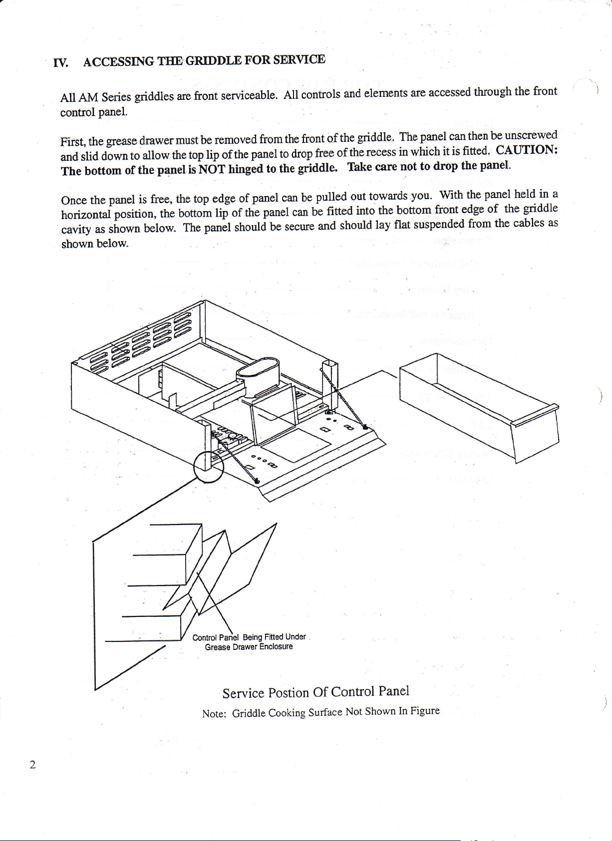
All
control
First,
and
The
ACCESSING
Series
griddles
panel.
grease
the
down
slid
bottom
drawer
to
the
of
allow
TIIE.GRIDDLE
serviceable.
front
are
must be
the
panet
removed
top lip
is NdT
of
ningla
FOR
the
SBRVICO
from
panel
to
All controls
the front
drop
to
the
of
free
griddle.
elements
and
griddle. The
the
recess
the
of
Thke
care
accessed
are
panel
in which
not to
drop
can
it is
through
be unscrewed
then
fitted.
the
CAUTION:
panel'
the
front
the
Once
horizontal
cavity
shown
u, ,ho*n
below.
panel
is
position,
free,
the
below.
the top
bottom
panel
The
edge
lip of
should
panel can be
of
panet
the
be secure
.*
pulled
fitted
br
and
towards
out
into the
should
you. With
bottom
flat suspended
lay
front
the
edge
from
panel
of
held
the
griddle
the cables
in a
as
Pariel Being
Control
Grease
Drawer
Service
Note: Griddle
Under
Fitted
Enclosure
Postion
Cooking
Control
Of
Surface
Not
Panel
Shown
In Figure
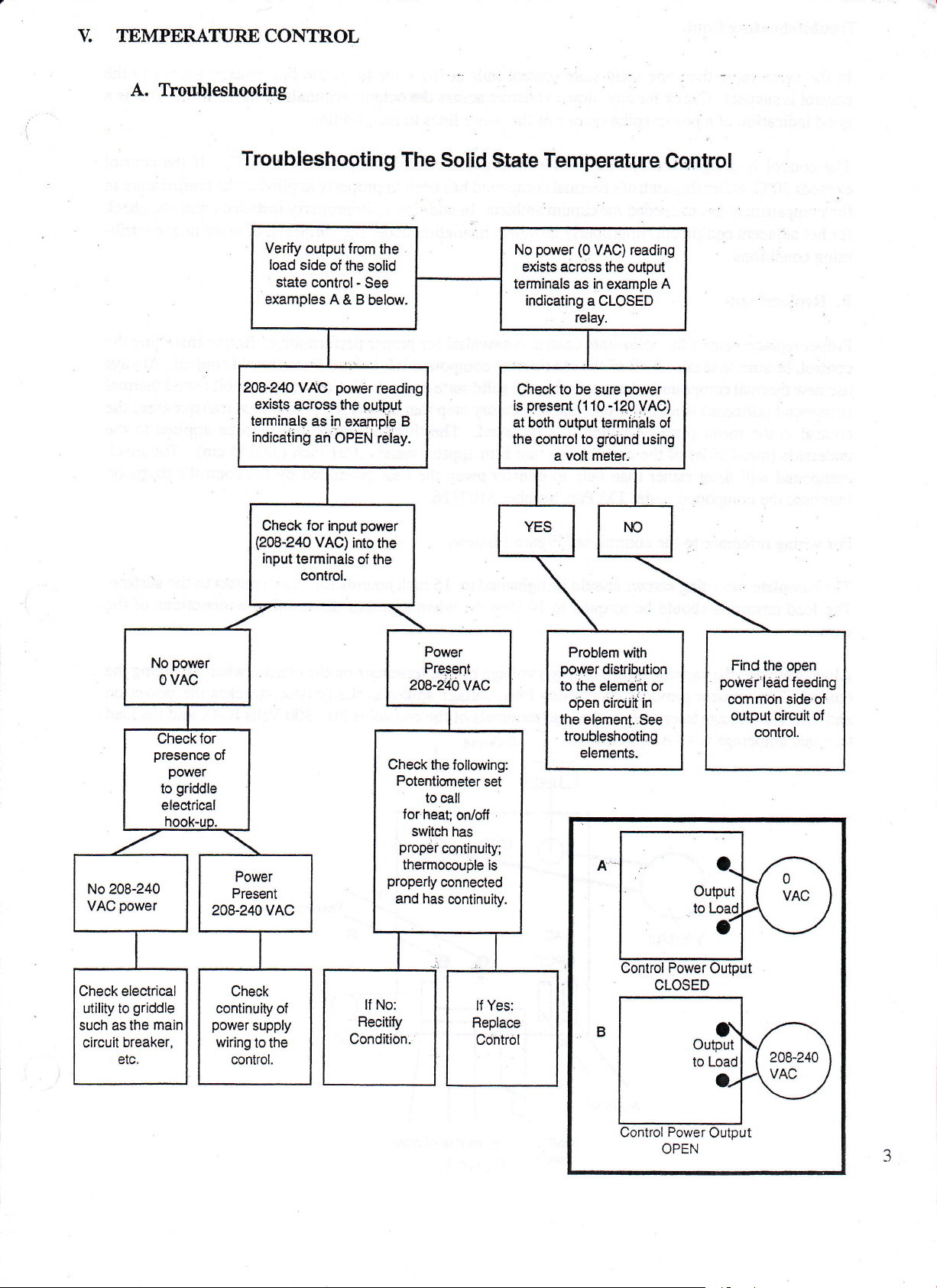
V. TEMPERATTJRECONTROL
A. Tboubleshooting
Troubleshooting
Verify output
load
side
state control-
examplesA&Bbelow
208-24o VAC
exists across
terminals
indicating
Check
(208-240
input
terminals
control.
from
the
of
power
the output
as in
exampie B
an OPEN
for
input
VAC)
inro
The
the
solid
See
reading
relay.
power
the
of the
Solid
State Temperature
power
a
(0
as in
relay.
(110
volt
a CLOSED
VAC) reading
the output
example
sure
-120
terminals of
ground
meter.
No
exists across
terminals
indicating
Check to be
present
is
at both output
the control to
Centrol
A
powel
VAC)
using
No
208-240
power
VAC
Check electrical
utility to
such as the
circuit
griddle
main
breaker,
ofF
Check
continuity
power
supply
wiring
to the
control.
of
Check
Potentiorneter
for
switch
proper
therrnocouple
properly
and has
lf No:
Recitify
Condition.
the following:
set
to call
heat;
onloll
has
continuity;
is
connected
continuity.
lf Yes:
Replace
Control
Problem
power
to the element
open
the element..See
troubleshooting
with
distribution
or
cilcUit in
elements.
CLOSED
Find
the open
power'ledd
common
output
feeding
side of
circuit
control.
o{
OPEN
Tfoubleshooting
Cont.
than one solid
In the event
control is suspect.
good
indication
The control
exceeds
compartment
the
for hot adjacent
more
of
is designed
eitherthe
70oC,
equipment, improperty installed insulation
Check
a
has exceeded
uting conditions.
B.
Replacement
Proper replacement
to clean off all of the old thermal compound
control, be
use new
compound
control to the
underside
compound
Purchase
sure
therrnal
compound when replacingthe solid
(silicone)
metal
(metal
will
side)
deter rather than help to transfer away
the compound
control fails
state
for
any blown
power
spike
on one
to
operate,with a
control's
thermal compound has
maximum
of the solid state
is an important and
plate
of
which it is mounted. The.thermal
orl
the
control as a
varistors
phase
of the
maximum heatsink
ambient.
control is essential for
mandatory
thin film
under TM Part Number 3103116.
same time, the
the
at
ouput
across
the
lines
to the
temperature of 7fC.
been improperly
In addition
to
under the
proper performance.
left behind
control. Use
state
that allows
step
approximately
heat
the
line voltage suppty to the
terminals
griddle
applied orthe temperature
improperly
elentents,
from the old
of'the special
proper
for
compound
inch
.001
generated
by the
Control. This is a
of the
If the control
in
installed controls, check
other heat contrib-
or
Before
installing the
control. Always
heat
is to be
(0A254
oil
based
transfer from the
applied to the
cm).
thermal
Too
much
control's thyristor.
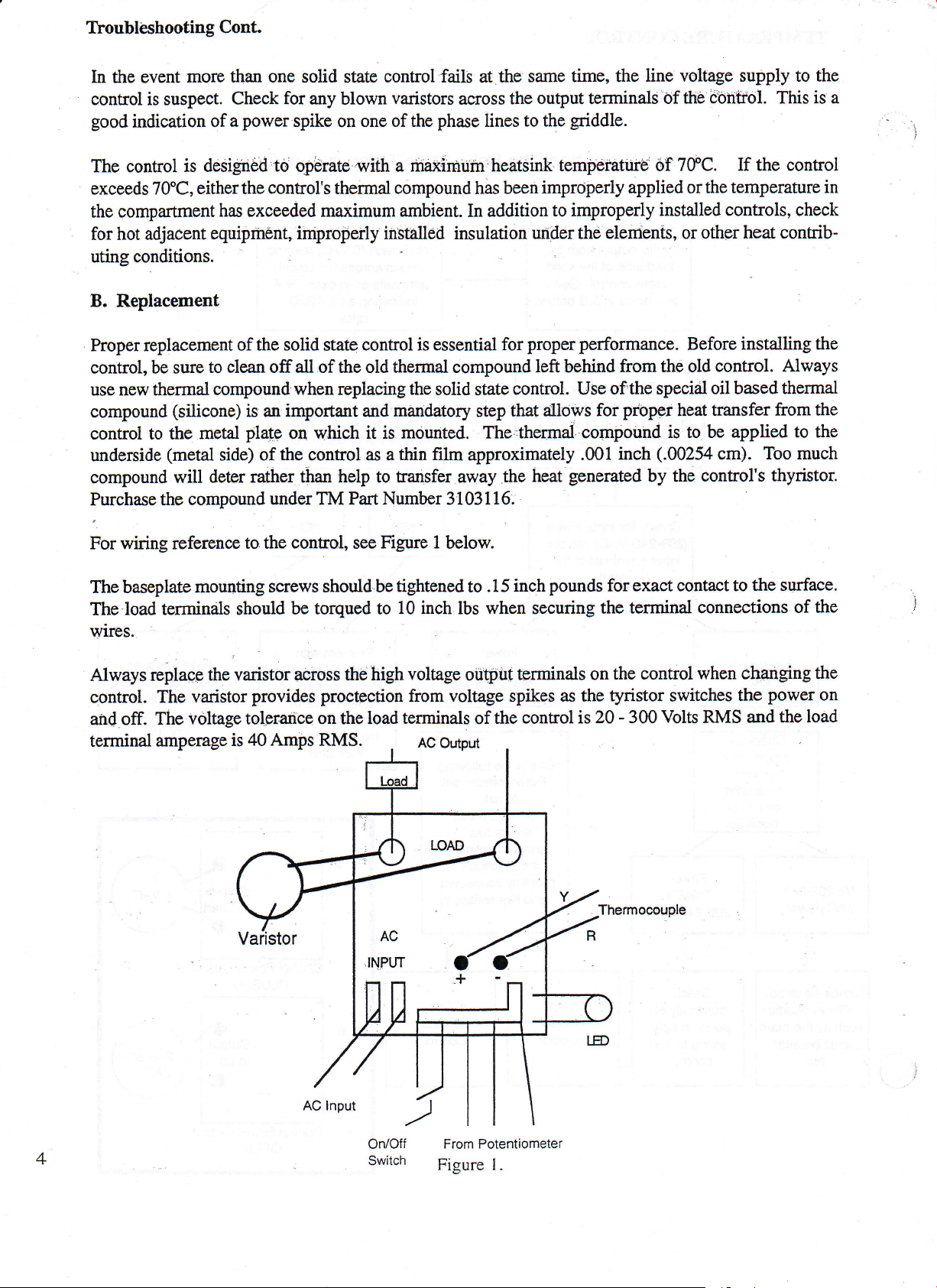
For wiring reference
The baseplate
The load
mounting
terminals should
wires.
Always
replaqp the
control. The
and
off.
The
terminal amperage
varistor across the high
varistor
voltage
is
to the
control,
Figure 1
see
screws should be
be torqued
to
provides proctoction
tolprarice on the load
40 Amps
RMS.
below.
tightened
10
voltage
inch
to
lbs
oiitput
from voltage
terminals
AC Output
of
pounds
inch
.15
whe:r securing
terminals on the
spikes as the
control is 20 - 300
the
for exact
contact to
the terminal
control. when
tyristor
switches
Volts
Thermocouole
the
surface.
connections of the
the
on
load
RMS
changing
power
the
and the
A
On/Off
Switch
Potentiometer
From
Figure I.
VI.
A. Ttoubleshooting
CALIBRATION
OF TIIE
POTENTIOMETER
Calibration
plate
tion
The allowable
this temperature
point
temperature.
B.
Calibrating
Note:Before
and all
with any
thermocouple
provide
(calibration)
when
taking
ment of
surface.
When taking
griddle
with
a
combination
from
ture
of the
should become
temperature
Procedure
making
panels
surface
piece
including
of the
for
the thermocouple
panels
at
a more
indicated
as
temperature
the temperature
OF THAI ZONE.
high
of
helps
probe.
the
potentiometer
jarred
range
paftrmeterthe
any calibration
the front
open
will
the control.
accurate
temperature
to aquire
This
calibration
in
Appendix
readings
probe
test
of the
the most
is
necessary
loose
from
its
of the
temperature
control
allow
The
insulation
gdddle
should
adjustments,
panel
for a
cooler
give
may
off
is
griddle,
temperature
accurate
an
even
A. A good
griddle
the
cmcial.
the
(1000
readings
only
after replacement
factory
is
must
inaccurate
though
See Figure
temperature
calibrated position.
15CPF(65'C)
fluctuate
griddle
the
be in
their closed position-
junction
indication.
the
control
K temperature
tvpe
surface for
8 for
probe
should
degrees
C) between
possible
of the
450'F(230.C)
to
no
more than
should
temperature
calibration
proper probe
probe
be
without the
up
be
at
Keeping
provide
does
indicator
should be
held down
the
controller
for
+14"F(j'C)
to
temperature
Calibrating
the connectiorrpoiniof
the
an ice
source
adjustrnents.
placement
placed
by an aluminum weight
probe
and
weight
absorbing
if
or
the
calibra-
each zone.
panelsrclosed
point
must
Proper
on thr
at the center
weight.
the
Within
from the
and cycling
griddle
the
reference
be
place-
griddle
of the
tempera-
set
the
will
used
This
1) Determine if
F(7"C) above
For Steps 2
2) Remove
Loosen
3)
remove.
4)
Turn the
5) Once
undershoot
6)
screw and the
7)
proper
Tighten the calibration
Replace
the temperature
or
below the
-7
refer
to figure
the temperature
the L/2" nut
screw in its
calibration
and cycle
area next to
the control
of
point
set
9
control
around
slot to
within
off
knob making
the
the left
has
been
14"F(7'C)
screw
the
screw with
and the
the center
of 350"F(175"C).
knob
to
potentiometer
to lower
obtained,
of
l/2"
a tamper
sure
it aligns
the
of
gain
access to
shaft and loosen
the
temperature
the
call for heat
overshoot.
potentiometer
proof
with
griddle
the 350'dial
surface
the calibration
or to the
LED will
nut
shellack.
for
that zone
adjustment
the calibration
right
illuminate
paint
and
indicaror
the head
is more than
screw but do not
to raise
within 14'F(7'C)
of the
mark.
screw.
temperature.
the
calibration
+14.

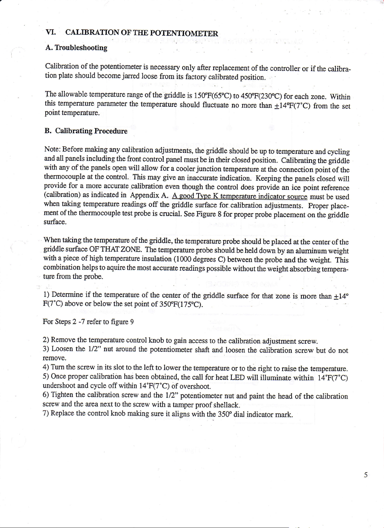
CALIBRATION
SOURCE
11-3t4"
(298.4Smm) (298.45mm)
THERMOCOUPLE
11-3t4j
LOCATION CHART
11-3t4'
(298.45mm)
6-5/32"
(ls,,/r']'ml
12-114',
(311.1Smm)
1-314"
(298.45mm)
AM36
1-314i
(3
11-314"
(298.45mm)
FT GRTDDLE)
6-5133
12.Uq
(311.15mm)
12-1/4J
(311.1
=Thermocouple
|
=
Thermocouple Locations
O
Locations
(24FT
4
GRIDDLE)
=
Thermocouple
Figure
8
Locations
6

Potentiometer
Calibration
Figure
9
$ss
r$s
Note: The
figure 10
below represents
Griddle.
Two waves
numbered | &2
a common temPerature
of l4"F(7"C)
as
the
graph
arc
setting
reveals.
Location
a temperature
the individual
of
350"F( I
75'C).
Behird
zones
of
I /2a
Knob
of the
properly
A
Nut
graph
taken
during
griddle.
2 ft
calibrated
the calibration
gdddle
The
griddle
will
have
of an
ANI24
was calibrated
a
Stolerance
at
Temperature
Swing
Figure
At 350eF
10

VII. IIEMING
A. Tloubleshooting
Start Here
ELEMENTS
Using an amprobe
check for
proper
amp draw at
leads to element.
if
to
the
the amps
griddle
Qualify
are
specifications.
See Chart
Fig.3.
Calibibtion
with
See calibration
seclion for'guidance.
p_rotlern
the control.
...=...jj
Check for
voltage
of
presence
to the
element and for
open circuits.
Track down
probable
cause.
Check for open
ciicUit
i6
element.
Check
voltage;
resistance of
8
incoming
check
element.
Charts
Figs.,2& 3.
cold
Prob-lem:..208- VAG
applied
griddfe
to 240
or wrong or
ddfeetive
VAC
el6ment,

common
most
The
circuits
short
circumstances,
The only
element.
element.
current.
placing the
when
grounded
Once
ture.
disconnecting
after
tion. Check
to
lead
or
the
to
way
Check
With an
this
If so,
or shorted
element
the
continuity
ground
for short
problems
ground
grounded
determine
across
amp
good
is a
volt meter from one
element
power
through
with
faults.
the leads
clip
is up
circuits.
A
element
if an element
meter,
indication
problems
to operating
griddle
to the
the element
grounded
for the
electric
check
heating
or
shorted
continue to
can
grounded
is
resistance
griddle
the
grounded
a
of
element
may
power
NOT
temperature
and disconnecting
for
open
elements
element
heat
or shorted
reading
ground
element.
lead to
unless
occur
the
circiuts
arc open
normally trip
will
without
and frorn
the element
element
one
and/or
tripping
is to
wire to
Check to see
element is
the
can be
element
ground
connections,;bad
a breaker.
a breaker.
disconnect
one lead
if there
see
case.
checked
lead
faults
all
ground
to
is any
power
if full
in mind that
Keep
up to operating
with an ohm
from the
power
and frorn
connections,
In some
wires from the
for a shorted
indication
can be
tempera-
distribu-
the
of
read
many
meter
element
referenced
As
griddle
perforrnance
Figure
ofthese
geatly
can
reveals
3
ratings
depending
below
in figure Z,the Accumiser
reduce
208 Volt
Maximum
Minumum
important
are+
the life
on the element
of
Element
Allowable
21 5 VAC
Allowable
1 92 VAC
Element
amperage
I07o.
voltage specific
is a
the element and/or
vs.
the electrical
240 Vott
Maximum
Minumum
Voltage Tolerances
Figure 2
and resistance
ratings
destroy the
service,
Element
Allowable
2s3 VAC
Allowable
VAC
21 6
the specific
of
griddle.
element
voltage elements.
wrong
The
immediatel!
voltage
or cause
l
Tolerances
to the
poor
Accumiser
Voltage
248
Voltage
240
lndividual
Element
Watts
31 20
Watts
3120
Ratings:
Resistance
Cold
Cold Resistance
Figure
Models
(Ohms)
13.87
(Ohms)
18.46
3
AM24,36
48
&
Draw
Amp
Element
Amp Draw
Element
Lgads
15.0
Leads
13.0
At
At

B.
Element Removal
elernents
The
heating
sf the
are
griddle
box assembly and
and the elimination
element'assembly
An
lower'the
front control
&
to,,be
surface,
ttre top heater
air
of
can
support bracket, itemA,
the Left and
the frame
tion cover
element assembly can
fonvard
Right side of the
supporf with the heater
and insulatiqn
be
out
position.
of
Alignment
Replacement
replaced
entrapment
as an
The
elements
plate.
assembly
This
between
be removed'through
panel
and
gain
to
then
the insulation
heater
assembly
access
assembly will pivot
mounted.below
pivoted
all
the
the
way down
ALWAYS!
are
specially
provides
the
the
to
frame
even heat
element and heater
front
of
elements.
the
item B. Thixl
strip,
support.
down. It
frame
support. Fourth.
and the element
.Failure
compressed
transfer
plate.
.'
griddle.
the
Seeond,
loosen
As
the nuts are
noj
is
necessary
once
assembly
to
do
between the
to the
Refer
remove
will
so
result in uneven
element
griddle
cooking
to Figure 4 belsw.
the front insulation
evenly, the'l/16" nuts
loosened,
front end
the
to remove the insula-
the nut$ arc removed, the
can be unwired and
package
surface
ErsL
on
of
slid
See figure 4
Proper
a) crush the
below for the following
alignment
of the top heater
thermocouple
b) cause improper
The heater
thermocouple
griddle
sure to tighten
tightly in
plate
tube
surface.
the
place.
has. a long
As the new element
Insutation
After replacing
the element
below the element
and
support bracke-t) are
abnormal
ing
compartment
performance
and
mounting
surface contact
slot
centered
as the element
package'box
retaining
assembly,
frame
support
ptit
with
back'in pl6ee.
temperatures
control
b)
component
explantions.
plate
and
therrnocouple
tube
of the element
at
the front,
assembly
in
bg
is
package
the
nuts
qure
lifted
evenly
that
the insulation
Failure
and
heat losS
failure
tube is
assembly with
is important
It
and secured
pivoted
is
box
until the
the 1.5" thic-k
cover.
from the
due
properly
to
element.
to heat.
Make
essential in
the bottom
that the
into
back
up into
order not to:
of the
slot
its flush
its installed
whole element
l,nsulation
sure items
install
This
sheet is
A & B
all inSulation will
can result in:
griddle
surface
certers around
position
under
position,
assembly
is level
:
properly installed
(front
insulation
result
poor
a)
the
the
be
and
in
cook-
10

eater
Assemb[y
lnsulation
Stand-Off
Package
Stand- O
Cotter Pih
The
Ng{ei
and the
as an
not need
pivoting
down.
insulation
exploded
to be
the
irrsulation
are
view
removed
element
lnsCorila
ver
cover
shown
do
and
while
assemblY
Frame
7/16" Nuts
Support
Frame
Support
Under
Element Assembly RemovaliReplacement
Figure
4
II

\rIII.
THERMOCOT]PLES
,
A.
Troubleshooting
Control Circuit
a) an open
b) a shorted
c) a reversed
thermocouple
thermocouple
wired
will inhibit
will
cause
thermocouple
will
the conirol
the control
cause
the
from operating
to
run
away
since it defaults
confiol to read
backwards
to
room tempemture
and runaway
Shorting the thermocouple
troubleshooting.
temperature
ing this very
naturally
and
brief
Since
TEST,
shorting
call for
be
service.
The
followingchartlists
the
Junction
Temp
90eF(32rC)
85eF(29e
SorF(zFC)
7seF(24eC)
good
is
a
way
the thermocouple
heat
if the
sure to
remove
Type
Kthermocouple
200eF
(93rC)
2.s2
2.U
2.75
2.86
to
see if
potentiometer
ttrre
the control
is the
same as
is
short from the circuit
millivoltreadingfrom200"F(93"C)
Griddle
Temperature
300eF
(149sC)
4.80
4.91
5.02
5.14 7.36
400eF
204ec)
7.02
7.13
725
quickly
bridging
responds
the circuit,
set at a higher
before
500eF
(260ec)
9.27
o?a
9.49
9.60
by coming
it will
temperature.
placing
When
griddle
the
to
500"F(26trC).
on
default
perform-
back into
during
to room
t2
Example:
should
At room
Cold resistance
The
thermocouple
be 4.91
mV.
temperature a good
reading:
70eF(24eC)
65e(18eC)
60eF(16eC)
millivolt
thermocouple
6.5
OHMS
average.
2.98
3.09
3.2A
reading
will
5.25
5.36 t.c6
5.47 7.69
at
300'F( 149"C) with
read
between 5-8
7.47
junction
a
ohms.
9.72
9.83
9.94
temperature
of 85.F(29.C)

B. Replacement
When
until
upward
of
rate
replacing
transition
the
iirto a channel
the surface.
temperature
the thermocouple;
crimp
Failufe
control of
toucheSthe
the bottom
at
position
to
gdddle
the
Thermocouple
it is imperative
tube'inlet.
Refef to
of thegriddle
the thetmocouple
adverse
and
imbedded
tube
into
bottom of
it
that
figure 5. Note
surface.
the
all
cooking
griddle
Thermocouple Placement
Figure 5
slides
way
into
enables accurate
This
into the support
results.
the
support
that the
tubsand is'inser'ted
thermocouple swings
temperature sensing
will cause inaccu-
tube
The thermocouples
couples
teristics
Terminal
nected
may also
the
of
connections
follows:
as
used
cause cooking
factory
YELLOW
are Type K.
No other
problems
since the control
installed thermocouple.
of the thermocouple
WIRE +
to
(POSITIVE)
thermcouple
typ"t
is
the control
RED
and
are to be used. Other
calibrated to the
are
WIRE
polarity
sensitive
(NEGATIVE)
length
and
K thermo-
type
and value
should
-.
charac-
con-
be
t3

IX.
The
through the
important
resistance
ON/OTF SWITCHES
On/Off switch is designed
switch are very
to set the
reading of 1.0
ohm meter
to
handle
small at 12 VAC.
on the
ohms or
R x 100
greater
currents
will
as
Therefore when
scale,to
drop the 12
higfr as 20 Amps.
checking
possible
read
VAC
resistances
and- cause
The
cunent values
the
switch for
to
up
the control not
running
continuity, it
Any
ohm.
1.0
to operate.
is
When
shown
replacing the rocker
in
figure 6. This
boot keeps
switch,
Added
Rubber
Boot
be sure that
grease
out
Switch
Figure
the switctr
and moisture,
Boot
6
has a
protective
preventing
boot
surrounding its
short circuits.
body as
l4
X. LIGIIT
The LED
heat.
light emitting
incorrectly
the black terminal.
If the
1.5 to 2.0 VDC
EMITTING
below each temperature
gdddle
to
the
diode is
rnay damage it.
DIODE
is heating
LED.
If the LED
If
polarity
See ftgare
(LED)
control
and maintaining
voltage
the
sensitive and
still does
knob
present,
is
The
7.
not illuminate,
.#
.".11,,-
+
LED
Figure
illuminates
temperature
the wires should
red LED
Polarity
7
when
yet
check
to
goes
wire
then it can
the
be sure the LED
that zone
LED is
not be reversed. Wiring
to the red
be
not
determined
griddle
of the
illuminating, check for
wired
is
terminal and
properly.
inoperative.
is
calling for
The
of the LED
the
black to

SCHEiVffiTICS
XI.
$$s
=
z
s.E9
6=5
Q€.v
542
i6 Fq
o xo
or
==
r'FE
I
I
x
N
EEH
$aB
€tg
=E
?
V-F
E;i
P
N
ll
t.
a
uF-
==
g
Eo
.F
-Ez
.
-#sE
€*-
+5t
=b
lv
t5

XL
SCHEWIATICS
i'i
-ltl
B
g.
C'
F
95
6g)
',:
o
o.
E+
of
F
-
F--ii
_Jt'
t
E+=
i
g
o !E O-'
.^.E
VEEx
H
EEffi;
lss
e[T
l6

XI. SCITEMATICS
-9
@J
EFE
lrJ
-x
u
I
I N
tH
\
vl
FE'<9
6 =:5
tl
t
N
z
o
E
H-
o
g
o
F
O9o
E;E
E FOI
o xo
=Jz
i
E6P
r+.=
<
-s.lo
tn c
E;
E$E
E
J
og?Ed
ooz
€o
GF
?:
z
17

_.1t,
e
X'I.
SCI{EMATICS
l1
?
6,1
Fnr
:=
d(J)
N
o-.
jlr
E+.
n€
\./=
*r--!*
xrA i
E N8=
|
st4
H
fT1
"r
PPls*
'a:
or
5 Y6E
*
F
A.E
tlJ
*
?'
g*-
c?
E
o-
g
-f,1
",
€,uo;
t!.
(D
in5
.9
-ty
P
= =?
s
i=-
Vs
-
?E
E=
tr.
E*;
'o
-1
Enl I
E
3
o
g!
E=
oo)
z,=
i4s=
6rH I
>r
- a=
E<
o<
F5
uIa
a_
i
,a\E
tlJ
Y€
L_
I
i
I
I
I
I
I
I
I
j
\-,
I8

XI. SCIIEMATICS
i$3
$$!
(el
Q€q
E!
682
l-i
t!
o
r!
-l
NI
$$!
-ct
=z
oo
ae
.b,Q
6Fa
f!:
6l
;Xf,
E;
t9

o lr,
-1ll
6
I
a,
x3
E'
F* E
-
a-
i nE_
q
V=- 9g
-s--.1
EKa=
E
stl
€
=
! F
d'
o-
::
o
lTl
xrll ;
Ey18=
6tY I
)L-io
;n5
9V6
ti=
I - ?-
t ;<
s
H3
rJJ
XL SCITEMATICS
3
</
=f
t-
Y=
6o
ql
(
Ei
a
Ex;
al,
___Jtr
E
9,
;iN
Y}
r
rit
NI
JI
Y=
..':
Flt
E' :
5*
-a-
nE X;
rvE
J:A
=l+
l
-o
! ltn
tlJ
-r-l-
;\lx- d
'g
t\v-
ott
>rr
+.
Fq
F
q
-g:
l*9
oi x=
$+.
n5
Y5
:
1,.
Fo
"F'
-
20
 Loading...