

Page 1
Owner’s Manual and Service Guide
ACcel-2-DC and ACcel-2-AC
May 2014
Page 2

Notes:
• Only authorized persons should be allowed to operate the vehicle. It is recommended that
the only persons allowed to operate the vehicle possess a valid motor vehicle driver’s
license.
• Don’t depress the accelerator pedal and parking pedal at the same time, or it will damage
the controller system and motor.
• Release the parking pedal before starting the vehicle, or it will damage the brake system as
well as other parts.
• Don’t modify the vehicle, or the performance and lifespan of the vehicle will be affected and
can cause safety issues.
• Don’t add any electronic equipment, such an on-board phone to avoid interference with the
control system.
• Don’t overload.
1
Page 3

Table of Contents
Specifications 3
Roof Installation 5
Operation 7
Operation layout 7
Dashboard 7
Switches 8
Pedals 8
Charging 9
Cigarette lighter 9
User information 9
Driver information 10
Driving 10
Operation procedure 10
Safety 11
Driving on slopes 11
Parking notes 11
Before initial use 12
Maintenance 12
Battery maintenance 13
Charging the battery group 15
Brake system maintenance 15
Steering system maintenance 15
Motor maintenance 16
Lubrication maintenance 16
Maintenance schedule 17
Troubleshooting 18
After-Sale Service 20
Monthly Maintenance Record 21
Electrical Diagrams 22
2
Page 4

Vehicle Specifications
Passengers
2
Battery group
48V, 8 x 6V, Trojan 105
Motor
7 HP KDS AC (64 PPR Encoder)
Controller power
Curtis 48V 450 Amp AC
Top speed (mph)
19.5 (20-25 LSV)
Load Capacity (lbs)
660
Weight including battery (lbs)
1360
Dimensions (in)
96 x 48 x 73
Ground clearance (in)
5
Turing Radius (ft)
11
Wheelbase (in)
66
Climbing capacity
30%
Front suspension
A-arm style independent suspension
Steering system
Rack and pinion
Brake system
4-wheel disc with mechanical foot e-brake
Tire size
205x50- 10 CST, DOT
Tire pressure (psi)
30
Drive train
Direct rear drive with 10.25:1 ratio
Front/rear tread (in)
37 / 39
Brake Distance (ft)
10
Charger
48V 17A
Charging time (hours)
8-10
ACcel-2-AC
3
Page 5

ACcel-2-DC
Passengers
2
Battery group
48V, 8 x 6V, 225AH
Motor
5.5 HP KDS DC Motor
Controller power
Curtis 48V 400 Amp DC 1268
Top speed (mph)
19.5 (20-25 LSV)
Load capacity
600
Weight including battery (lbs)
1350
Dimensions (in)
96 x 48 x 73
Ground clearance (in)
5
Turing Radius (ft)
12
Wheelbase (in)
65
Climbing capacity
30%
Front suspension
A-arm style independent suspension
Steering system
Rack and pinion
Brake system
4-wheel disc with mechanical foot e-brake
Tire size
205x50- 10 CST, DOT
Tire pressure (psi)
30
Drive train
Direct rear drive with 10.25:1 ratio
Front/rear tread (in)
37 / 39
Brake Distance (ft)
10
Charger
48V 18A
Charging time (hours)
8-10
4
Page 6
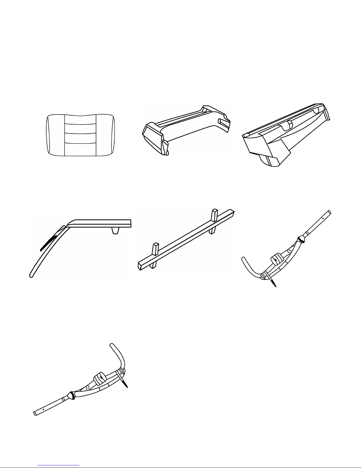
Roof Installation
Backrest
Rear lid
Windshield trim cover
Roof kit
Backrest bracket
Rear column (Right)
Rear column (Left)
Pre-Installation preparation: Check the kit list as per below.
1|
4|
2|
5|
3|
6|
7|
5
Page 7

Installation procedure
t bracket
Install the backrest and rear box according to
shown left for next installation.
ng the
installation to avoid surface scratches or other
First step
Put the rear columns (right and left) into the
corresponding holes. Attach it to the chassis by
M10 bolts. Then install the backres
with a M6*40 round screw, tighten.
Second step
the location shown left. Attach the backrest by 4
M8 hex bolts, and attach the rear box by the M5
oversized head break mandrel rivets.
Put the windshield trim cover to the location
Third step
Install the roof and windshield. Attach it with
M8*45 Hexagon bolts at the indicated location.
Ensure the correct position after tightening all
connections. Take caution duri
damages of parts.
6
Page 8
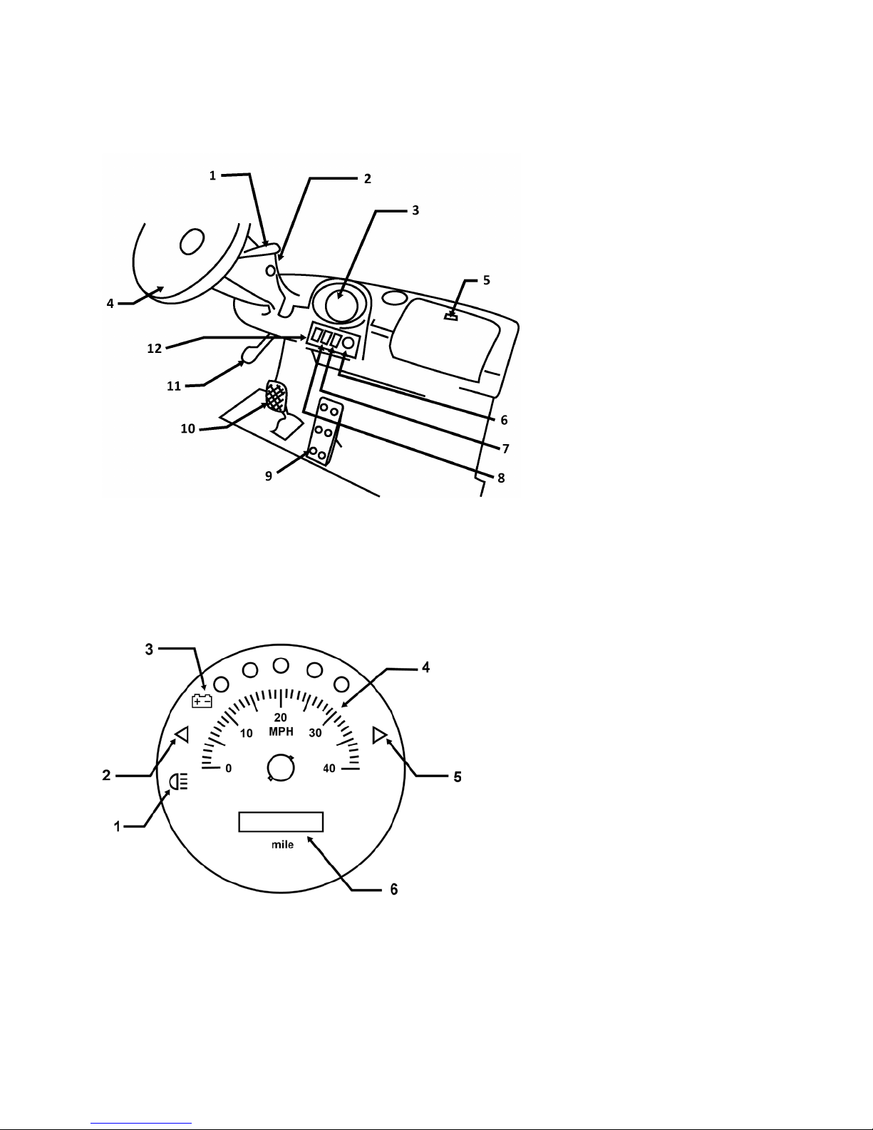
Operations
1| Combination switch
2| Key switch
3| Dash display
4| Steering wheel
5| Glove-Box
6| Cigarette lighter
7| High/Low speed switch
8| Light switch
9| Accelerator pedal
10| Brake pedal
11| Parking brake pedal
12| F/R Switch
Dashboard
1| High Beam
2| Left turn signal
3| Battery indicator
4| Speed
5| Right turn signal
6| Odometer
7
Page 9

Key switch
Normal park position, only at this position can you remove the key.
All the power of your car is connected when key is at this position.
WARNING: Do not take out the key when the vehicle is running. Do not leave the key alone,
especially with children, to avoid any accident.
Forward/Backward switch
The switch has three positions. The vehicle goes forward when FWD is pressed down and backward
when REV is pressed down. When the switch is unmoved, the vehicle is in the neutral position.
WARNING: Strictly prohibit shifting forward and backward directly when the system is
running, or it will damage the transmission system.
Combination switch
Turn the bar on the end of combination switch to turn on or off the lights. The small lights and head
light will be on when on this position. All lights will be off when it is on the OFF position.
When the ignition light is on ACC or ON position, pulling the switch forward will signal right.
Pushing it backward will signal left.
Pedals
Depress the accelerator to move forward and backwards. Depress the brake pedal to lower the
speed until the vehicle stops.
Put down the parking brake pedal to engage the parking brake, press again to release.
8
Page 10

WARNING: Before leaving the cart, put the Forward/ Backward switch in the neutral position to
park. The Forward/ Backward switch should be on neutral position when releasing the parking as
well. Before running the parking brake should be released, or it may seriously damage the brake
system and related parts.
Charging
Charger Socket
Plug one terminal of batter into charger socket (see picture), and plug the other terminal into main
power when recharging the batteries.
Cigarette lighter
The ignition power is DC12V.
User Information
Read the specification of vehicles, and use vehicles according to manufacturer recommendation.
Do not modify the vehicles without manufacturer’s approval. Any modifications will affect the
function and safety of vehicles.
Any replacements of the spare parts (such as changing the battery, tires, seats, and so on) shouldn’t
affect the safety requirements.
This is a low speed electric vehicle, and should be used on approved roads and meet the road
regulations.
9
Page 11

Driver information
Only authorized persons shall be allowed to operate the vehicle. It is recommended that only
persons with a valid motor vehicle driver’s license be allowed to operate the vehicle.
The driver should pay close attention to road conditions, passerby and the other vehicles on the
road.
Remind passengers not to leave the seats and keep arms and legs inside the vehicle when it is
moving.
Report to related departments once any accidents occur.
The driver should not modify, add or remove any parts of the vehicle. Do not add or install any
additional handlebar on steering wheel if they are not original design.
The driver should operate vehicles in approved areas.
Driving
Operation Procedure
1| Insert the key and turn it to ON position.
2| Press the green head of the direction selector to the forward position.
3| Release the parking brake and press the accelerator pedal. The speed will get increase as pedal
is pressed downwards.
4| When stopping the cart release the accelerator pedal and depress the brake pedal slowly. Then
push down the parking pedal after stopping.
10
Page 12

Safety
Release the parking pedal before driving to avoid any damage of the brake shoes or motor.
Don’t depress the accelerator pedal too aggressively or frequently or it will shorten the life of the
accelerator and controller system.
Don’t start, stop, or turn in high speed.
Do not pass other vehicles traveling in the same direction at intersections, blind spots, or at other
dangerous locations.
Avoid running over loose objects, potholes, and bumps to avoid the damage of the vehicle and the
surroundings or hurting passengers.
Please observe and obey all traffic regulations, including the carry capacity requirement, authorized
speed limits, and other marks.
Keep a clear view of the path of travel. Observe other traffic and pedestrians, and maintain a safe
distance, based on speed of travel, from a vehicle ahead.
Driving on Slopes
Ascend or descend grades slowly.
Do not turn around when driving on a slope.
Be careful when driving near to the edge of the slope. Please keep at least a wheel distance from the
vehicle to the edge of the platform.
Parking Notes
Park the cart on the flat and solid ground.
Depress the brake pedal. Keeping the direction switch in neutral position, turn off the ignition
switch and take out the key.
Fix the wheels when parking the cart on the slope.
11
Page 13

Before Initial Use
Read, understand and follow the safety label on the instrument panel. Be sure you understand how
to operate the vehicle, its equipment and how to use it safely. Maintaining good performance
depends to a large extent on the operator.
New Vehicle Inspection
Before a new vehicle is put into operation, the items shown below must be performed.
1| Check status of each spare part, especially the screw and nut on the steering wheel and brake.
2| Check for any leakage problems with the steering system , turning system and transaxle.
3| Check the electrolyte level of the battery.
4| Check if tire inflation is correct. Low pressure will lead to difficulty turning and bumpy riding.
5| Check if there is any damage between the wiring and other locations where pieces rub against
each other.
Maintenance
Turn off the electricity, take out the key and engage the parking brake.
When working underneath vehicles, please use jack and triangle wood to fix the front and rear
wheels, in order to avoid accidents.
Keep the maintenance area clean and safe.
Please perform vehicle maintenance according to safety guidance.
No smoking in the working sites. The facility of extinguishing fire should exist in the working sites.
Don’t use fire to check the height and leakage of the electrolytes in the reserve battery. Don’t use
the flammable liquids to wash off parts.
12
Page 14

Maintain the ventilation of working sites.
Check and maintain under safe working conditions. Check and maintain the braking, steering, speed
direction control system, emergency facilities, head/rear lights, controller, and safety equipment.
Check the battery cover as per the right methods.
Battery Maintenance
The batteries for this vehicle have high current, high capacity, and a long lifetime. To keep the
vehicle in good performance, it is very important to maintain it in the correct procedure.
The connectors on the batteries are the output connectors. Keep the area clean and dry, with no
foreign matter or dust on it, or the leakage or short-circuit. This will shorten the battery life or
possibly burn it out.
WARNING: Don’t let tap water enter the battery.
Check the height of the electrolyte periodically. Check it once per week in summer and once every
two weeks the rest of the year. Standard height level is 10-15mm (½“) higher than the battery
plate. If is too low, please add the recommended distilled water or liquid.
Keep the wiring well-connected. After using the vehicle initially for 2-3 days, the completed
inspection for all connectors should be carried out. Inspect the vehicle once a week following. Any
loose or rusty connectors should be fixed. Loose or rusty connectors can cause high temperature,
damage, or possible sparking.
NOTE: Don’t over-tighten terminals.
Charge the battery immediately after discharge, or it will affect the battery life.
Keep the filling-water container clean, so no impurities will be put into the battery.
When the environment temperature is under -40° F, the density of the electrolyte after charging is
3
1.28 - 1.29 g/cm
immediately to keep the electrolyte value to normal. If the battery discharges by 80% (the
electrolyte is between the range 1.13 - 1.15 g/cm
. If it is more than 1.30 g/cm3, the battery can be damaged badly. Add water
3
), charge it immediately. At this range the vehicle
can only last 2 - 3 mi. Don’t discharge any longer, or it will damage the battery.
Charge the battery fully before storage. Charge it at least once a month for 24 hours.
13
Page 15

Battery Replacement
Replace the batteries immediately when it approaching to the battery life, as the capacity will
decrease quite fast and can’t meet the range requirement. The detailed replacement way can be
consulted with the supplier.
Remove battery hold downs and cables. Lift out batteries with a commercially available lifting
device.
If the batteries have been cleaned and any acid in the battery rack area neutralized as
recommended, no corrosion to the battery racks or surrounding area should be present. Any
corrosion found should be immediately removed with a putty knife and a wire brush. The area
should be washed with a solution of sodium bicarbonate (baking soda) and water and thoroughly
dried before priming and painting with a corrosion resistant paint.
The batteries should be placed into the battery racks and the battery hold downs tightened to 45 -
55 in. lbs. (5 - 6 Nm) torque, to prevent movement but not tight enough to cause distortion of the
battery cases.
Inspect all wires and terminals. Clean any corrosion from the battery terminals or the wire
terminals with a solution of sodium bicarbonate (baking soda) and brush clean.
WARNING: To prevent battery explosion that could result in severe personal injury or
death, extreme care must be used with aerosol containers of battery terminal protectant.
Insulate the metal container to prevent the metal can from contacting battery terminals
which could result in an explosion.
Use care to connect the battery wires as shown. Tighten the battery post hardware to 50 70 in. lbs.
(6 -8 Nm) torque. Protect the battery terminals and battery wire terminals with a commercially
available protective coating.
Battery Connections
14
Page 16

Charging the Battery group
In order to guarantee battery life, please use the recommended charger to charge the cart.
Keep the key switch on OFF position during charging.
Keep the battery in cool, dry location. Don’t use the charger in rain or hot weather.
Don’t overcharge the battery, or it the electrolyte will expel from the battery which can damage the
vehicle and the storage performance of the battery.
Ensure that the AC power is consistent with the input power. After connected, the green light
indicates the vehicle is charging. The red light indicates that charging is complete. At this time the
power will be cut off automatically to avoid overcharging.
Charging should be monitored.
NOTE: Don’t remove the plug connected to the vehicle prior to disconnecting from the AC
power source.
Brake System Maintenance
Adjust the gap between the brake drum and brake shoes.
Dial up the adjusting ratchet wheel of the brake drum until the
wheel cannot turn freely, then dial down the ratchet wheel 7 - 8
teeth.
Steering System Maintenance
Check if there is any damage to the dust cover of the tie-rod. A broken dust cover will let water in
and damage the tie-rod, and the steering system will not be flexible. Replace a new one immediately
once a worn one is found. Make sure the front wheel toe-in is between 3 - 5 mm (1/8 – 3/16”). If it
exceeds this value, adjust the tie-rod screw stem.
15
Page 17

Motor Maintenance
Keep the motor surface clean at all times. Clean the surface with a dry cloth. Avoid any water
entering into the motor.
Lubrication maintenance
Check the brake once a month. Fill it full if the oil is low.
The gear oil should be changed once a year. User can choose gear oil according to the climate.
• Summer: GL-4 90
• Winter: GL-80W/90
Replace the grease for the rear axle once a year, using recommended oil type GL-5 90 and GL-5
80W/90. Fill the level to 1.2 liters (40 oz).
When changing, first twist down the oil plug to discharge the gear oil. Clean the oil plug and replace
it, then inject the new gear oil.
16
Page 18

Maintenance Schedule
Check tire pressure
Check tires for abrasions
Check tightness of the bearing bolt and the tire nut
Tire rotation
Check braking and the parking function
Check brake tube for leakage
Check if brake shoes are worn
Check if steering wheel works freely
Check brake pump
Check tightness for the turning ball joint and rod
Check nut on the steering rack’s spindle
Check tightness of steering rack and bracket
Inspect and adjust front wheel’s toe-in
Checking tightness of front absorber and helix spring
Check height of electrolyte
Check density of electrolyte
Check if the battery’s pole is loose
Clean battery pole by water
Check light and relay performance
Clean and fix wiring connector
Check and adjust front tire’s bearing
Check or replace transaxle
Check performance of gearbox and bearing (after the first
Check motor’s bolts and nuts
Clear and lubricate front wheel bearing
Checking motor bearing
Lubricate other parts (use general oil)
Item weekly monthly quarterly
17
Page 19

Troubleshooting
Operation procedure is
wrong
Refer to user manual
Wiring connector is
eroded
Cut off the power, remove the nut,
clean the connector and replace the
nut
Battery power is low
Charge the battery
Direction switch is
damaged
Replace part
Accelerator is damaged
Replace part
Direction contactor is
damaged
Replace part
Wiring is loose
Repair or replace parts
Vehicle is overloaded
resulting in the
167° F
Lighten the load of the vehicle to
decrease the temperature
Releasing the accelerator pedal
The spring for the
accelerator pedal is
cannot reposition
Shut off the ignition lock, step on the
parking pedal ,then contact with the
The authorized qualification for repair, the requirement for application, safety and the
maintenance requirement should be the same.
Problem Possible reason Processing methods
Cart cannot move
Vehicle moves slowly and/or
stops when climbing
does not slow down the vehicle
shutting off the
controller when
temperature reaches
broken and the pedal
18
supplier
Page 20

No indication (LEDs) on the
dashboard
Parts are loose
Lock the inserted parts
Fuse is burned out
Replace the fuse
Bumpy riding
The tire pressure is
unbalanced
Balance the air pressure
The front and rear
wheel are not aligned
Correct the assembly of the wheels
Tire pressure is too
low
Inflate tires
Shaft is short of
lubrication.
Add lubrication
The direction shaft pin
or joints are damaged
Replace parts
Tie-rod is damaged
Replace part
Steering rack has not
been adjusted well or
abased
Adjust or replace
The direction shaft is
loose
Tighten direction shaft
Low battery power
Charge the battery
Damaged drive gear
Replace
Speed control system
is faulty
Maintain speed control system
Axle of the tire or the
washer is damaged
Replace parts
Too much oil
Reduce oil quantity
Turning is difficult
Turning excessively
Lack of power, slow response
Rear bearing is leaking oil
19
Page 21

Abnormal noise
Drive gear or the
bearing is damaged
Replace part
Bearing of front or
rear suspension is
damaged
Adjust or replace
Wheel screw is loose
Tighten
Motor’s bearing is
damaged
Replace part
Brake drum is
damaged
Replace part
Brake shoe is not clean
Keep clean
Low braking power
These possible causes are just for your reference and do not include all causes that result in these
listed issues.
After-Sale Service
Star EV will provide the friendly service and technical support for the users.
Users can report faulty problems by telephone, fax and email. Keep Star EV informed for the model
number, VIN number, estimated delivery time, contract number and date as well as a detailed
description or photos of the faulty parts and problems, and our team will handle it accordingly.
Do not disassemble.
20
Page 22

Monthly Maintenance record
Is tire pressure normal? Are
wing nuts tightened?
Is the batteries’ liquid level
normal?
Any batteries or controller
motor wirings loose?
Is the controller system
normal?
Is the fixed screw for the
steering system normal?
Are the wiring connectors
clean?
Are the body and the frame of
the vehicle normal?
Are the front axle and rear
axle normal?
Record VIN NO: Date
Normal Abnormal Remarks
21
Page 23

Electrical Diagram for AC Controller
22
Page 24

Electrical Diagram for DC Controller
23
Page 25

24
 Loading...