

Star 824M, 824T, 836M, 836T, 836TS Installation And Operating Instructions Manual
...
Star
Manufacturing
International Inc.
Installation and
Operating Instructions
10 Sunnen Drive
St. Louis, MO 63143
Phone: (314) 781-2777
Fax: (314) 781-2714
Instructions d’installation
et d’opération
2M-Z4877 Rev. E 8/3/2006
ULTRA-MAX™ GAS GRIDDLE MODELS
GRILS A GAZ ULTRA-MAX MODELES
824M 824T 824TS 824TSCHS
836M 836T 836TS 836TSCHS
848M 848T 848TS 848TSCHS
860M 860T 860TS 860TSCHS
872M 872T 872TS 872TSCHS
WARNING: Improper installation,
adjustment, alteration, service or
maintenance can cause property
damage, injury or death. Read the
installation, operating and maintenance
instructions thoroughly before installing
or servicing this equipment.
AVERTISSEMENT: L’installation inexacte, le ré-
glage, le changement, le service ou l’entretien peuvent causer des dégats matériels, des dommages
ou la mort. Lisez les instructions d’installation,
d’opération et d’entretien complètement avant
d’installer ou entretenir ce matériel.
FOR YOUR SAFETY: Do not store or
use gasoline or other fl ammable vapors or
liquids in the vicinity of this or any other
POUR VOTRE SÛRETÉ: N’enregistrez pas ou
n’utilisez pas l’essence ou d’autres vapeurs ou liquides infl ammables à proximité de ceci ou d’aucun
autre appareil.
WARNING: This appliance shall be
installed in accordance with current
regulations and used only in wellventilated space. Refer to instructions
before installing and using this
AVERTISSEMENT: Cet appareil sera installé
selon des règlements actuels et utilisé seulement dans l’espace bien-aéré. Référez-vous aux
instructions avant d’installer et utiliser cet appareil.
In addition, there should be posted, in a
prominent location, detailed instructions
to be followed in the event the operator
smells gas. Obtain the instructions from
the local gas supplier.
En outre, là devrait être signalé, dans un emplacement en avant, des instructions détaillées d’être
suivi en cas que l’opérateur sent le gaz. Obtenez
les instructions du fournisseur local de gaz.
1

SAFETY SYMBOL
Using any part other than genuine Star factory supplied parts relieves the
manufacturer of all liability.
Star reserves the right to change specifi cations and product design without
notice. Such revisions do not entitle the buyer to corresponding changes,
improvements, additions or replacements for previously purchased
equipment.
Due to periodic changes in designs, methods, procedures, policies and
regulations, the specifi cations contained in this sheet are subject to change
without notice. While Star Manufacturing exercises good faith efforts to provide
information that is accurate, we are not responsible for errors or omissions
in information provided or conclusions reached as a result of using the
specifi cations. By using the information provided, the user assumes all risks in
connection with such use.
These symbols are intended to alert the user to the presence of
important operating and maintenance instructions in the manual
accompanying the appliance.
RETAIN THIS MANUAL FOR FUTURE REFERENCE
NOTICE
MAINTENANCE AND REPAIRS
Contact your local authorized service agent for service or required maintenance. Please record the model
number, serial number, voltage and purchase date in the area below and have it ready when you call to
ensure faster service.
Model No.
Serial No.
Voltage
Purchase Date
Authorized Service Agent
Reference the listing provided with the unit
or
for an updated listing go to:
Website: www.star-mfg.com
E-mail Service@star-mfg.com
Telephone: (800) 807-9054 Local (314) 781-2777
The Star Service Help Desk
Business 8:00 am to 4:30 p.m. Central Standard Time
Hours:
Telephone: (800) 807-9054 Local (314) 781-2777
Fax: (800) 396-2677 Local (314) 781-2714
E-mail Parts@star-mfg.com
Service@star-mfg.com
Warranty@star-mfg.com
Website: www.star-mfg.com
Mailing Address: Star Manufacturing International Inc.
10 Sunnen Drive
St. Louis, MO 63143
U.S.A
2
2

SPECIFICATIONS:
824M
2 Controls, 60,000 BTUH, 573 sq. in. (3697 sq. cm) Grid Area
Approximate weight: installed - 214 Lb s (97.0 kg), shipping - 244 Lbs (110.6 kg)
Dimensions: 24" - Width, 32 3/8" - Depth, 18" - Height
(61 cm - Width, 82.2 cm - Depth, 45.7 cm - Height)
Type: Manual Valve
836M Type: Manual Valve
3 Controls, 90,000 BTUH, 860 sq. in. (5545 sq. cm) Grid Area
Approximate weight: installed - 321 Lbs (145.4 kg), shipping - 366 Lbs (165.8 kg)
Dimensions: 36" - Width, 32 3/8" - Depth, 18" - Height
(91.4 cm - Width, 82.2 cm - Depth, 45.7 cm - Height)
848M Type: Manual Valve
4 Controls, 120,000 BTUH, 1146 sq. in. (7394 sq. cm) Grid Area
Approximate weight: installed - 428 Lbs (193.9 kg), shipping - 488 Lbs (221.1 kg)
Dimensions: 48" - Width, 32 3/8" - Depth, 18" - Height
(122 cm - Width, 82.2 cm - Depth, 45.7 cm - Height)
860M Type: Manual Valve
5 Controls, 150,000 BTUH, 1433 sq. in. (9242 sq. cm) Grid Area
Approximate weight: installed - 535 Lbs (242.4 kg), shipping - 610 Lbs (276.4 kg)
Dimensions: 60" - Width, 32 3/8" - Depth, 18" - Height
(152.4 cm - Width, 82.2 cm - Depth, 45.7 cm - Height)
872M Type: Manual Valve
6 Controls, 180,000 BTUH, 1719 sq. in. (11091 sq. cm) Grid Area
Approximate weight: installed - 642 Lbs (290.9 kg), shipping - 732 Lbs (331.7 kg)
Dimensions: 72" - Width, 32 3/8" - Depth, 18" - Height
(182.9 cm - Width, 82.2 cm - Depth, 45.7 cm - Height)
824T Type: Throttling Control
2 Controls, 60,000 BTUH, 573 sq. in. (3697 sq. cm) Grid Area
Approximate weight: installed - 220 Lb s (99.7 kg), shipping - 246 Lbs (111.5 kg)
Dimensions: 24" - Width, 32 3/8" - Depth, 18" - Height
(61 cm - Width, 82.2 cm - Depth, 45.7 cm - Height)
836T Type: Throttling Control
3 Controls, 90,000 BTUH, 860 sq. in. (5545 sq. cm) Grid Area
Approximate weight: installed - 330 Lbs (149.5 kg), shipping - 369 Lbs (167.2 kg)
Dimensions: 36" - Width, 32 3/8" - Depth, 18" - Height
(91.4 cm - Width, 82.2 cm - Depth, 45.7 cm - Height)
848T Type: Throttling Control
4 Controls, 120,000 BTUH, 1146 sq. in. (7394 sq. cm) Grid Area
Approximate weight: installed - 440 Lbs (199.4 kg), shipping - 492 Lbs (222.9 kg)
Dimensions: 48" - Width, 32 3/8" - Depth, 18" - Height
(122 cm - Width, 82.2 cm - Depth, 45.7 cm - Height)
860T Type: Throttling Control
5 Controls, 150,000 BTUH, 1433 sq. in. (9242 sq. cm) Grid Area
Approximate weight: installed - 550 Lbs (249.2 kg), shipping - 615 Lbs (278.7 kg)
Dimensions: 60" - Width, 32 3/8" - Depth, 18" - Height
(152.4 cm - Width, 82.2 cm - Depth, 45.7 cm - Height)
872T Type: Throttling Control
6 Controls, 180,000 BTUH, 1719 sq. in. (11091 sq. cm) Grid Area
Approximate weight: installed - 660 Lbs (299.0 kg), shipping - 738 Lbs (334.4 kg)
Dimensions: 72" - Width, 32 3/8" - Depth, 18" - Height
(182.9 cm - Width, 82.2 cm - Depth, 45.7 cm - Height)
3

824TS
2 Controls, 60,000 BTUH, 573 sq. in. (3697 sq. cm) Grid Area
Approximate weight: installed - 222 Lb s (100.6 kg), shipping - 250 Lbs (113.3 kg)
Dimensions: 24" - Width, 32 3/8" - Depth, 18" - Height
(61 cm - Width, 82.2 cm - Depth, 45.7 cm - Height)
Type: Snap Action Control With Safety Pilot
836TS Type: Snap Action Control With Safety Pilot
3 Controls, 90,000 BTUH, 860 sq. in. (5545 sq. cm) Grid Area
Approximate weight: installed - 333 Lbs (150.9 kg), shipping - 375 Lbs (169.9 kg)
Dimensions: 36" - Width, 32 3/8" - Depth, 18" - Height
(91.4 cm - Width, 82.2 cm - Depth, 45.7 cm - Height)
848TS Type: Snap Action Control With Safety Pilot
4 Controls, 120,000 BTUH, 1146 sq. in. (7394 sq. cm) Grid Area
Approximate weight: installed - 444 Lbs (201.2 kg), shipping - 500 Lbs (226.6 kg)
Dimensions: 48" - Width, 32 3/8" - Depth, 18" - Height
(122 cm - Width, 82.2 cm - Depth, 45.7 cm - Height)
860TS Type: Snap Action Control With Safety Pilot
5 Controls, 150,000 BTUH, 1433 sq. in. (9242 sq. cm) Grid Area
Approximate weight: installed - 555 Lbs (251.5 kg), shipping - 625 Lbs (283.2 kg)
Dimensions: 60" - Width, 32 3/8" - Depth, 18" - Height
(152.4 cm - Width, 82.2 cm - Depth, 45.7 cm - Height)
872TS Type: Snap Action Control With Safety Pilot
6 Controls, 180,000 BTUH, 1719 sq. in. (11091 sq. cm) Grid Area
Approximate weight: installed - 666 Lbs (301.8 kg), shipping - 750 Lbs (339.8 kg)
Dimensions: 72" - Width, 32 3/8" - Depth, 18" - Height
(182.9 cm - Width, 82.2 cm - Depth, 45.7 cm - Height)
824TSCHS Type: Snap Action With Safety Pilot and Chrome Plate
2 Controls, 60,000 BTUH, 573 sq. in. (3697 sq. cm) Grid Area
Approximate weight: installed - 222 Lb s (100.6 kg), shipping - 250 Lbs (113.3 kg)
Dimensions: 24" - Width, 32 3/8" - Depth, 18" - Height
(61 cm - Width, 82.2 cm - Depth, 45.7 cm - Height)
836TSCHS Type: Snap Action Control With Safety Pilot and Chrome Plate
3 Controls, 90,000 BTUH, 860 sq. in. (5545 sq. cm) Grid Area
Approximate weight: installed - 333 Lbs (150.9 kg), shipping - 375 Lbs (169.9 kg)
Dimensions: 36" - Width, 32 3/8" - Depth, 18" - Height
(91.4 cm - Width, 82.2 cm - Depth, 45.7 cm - Height)
848TSCHS Type: Snap Action Control With Safety Pilot and Chrome Plate
4 Controls, 120,000 BTUH, 1146 sq. in. (7394 sq. cm) Grid Area
Approximate weight: installed - 444 Lbs (201.2 kg), shipping - 500 Lbs (226.6 kg)
Dimensions: 48" - Width, 32 3/8" - Depth, 18" - Height
(122 cm - Width, 82.2 cm - Depth, 45.7 cm - Height)
860TSCHS Type: Snap Action Control With Safety Pilot and Chrome Plate
5 Controls, 150,000 BTUH, 1433 sq. in. (9242 sq. cm) Grid Area
Approximate weight: installed - 555 Lbs (251.5 kg), shipping - 625 Lbs (283.2 kg)
Dimensions: 60" - Width, 32 3/8" - Depth, 18" - Height
(152.4 cm - Width, 82.2 cm - Depth, 45.7 cm - Height)
872TSCHS Type: Snap Action Control With Safety Pilot and Chrome Plate
6 Controls, 180,000 BTUH, 1719 sq. in. (11091 sq. cm) Grid Area
Approximate weight: installed - 666 Lbs (301.8 kg), shipping - 750 Lbs (339.8 kg)
Dimensions: 72" - Width, 32 3/8" - Depth, 18" - Height
(182.9 cm - Width, 82.2 cm - Depth, 45.7 cm - Height)
4

CAUTION
GENERAL INSTALLATION DATA
This equipment is designed and sold for commercial use only by personnel trained and experienced
in its operation and is not sold for consumer use in and around the home nor for use directly by
the general public in food service locations.
Before using your new equipment, read and understand all the instructions & labels
associated with the unit prior to putting it into operation. Make sure all people associated
with its use understand the units operation & safety before they use the unit.
Ultra-Max series griddles are equipped for use on either natural or propane gas. All units
are shipped for natural gas and can easily be converted to propane. See Propane Gas Conversion.
-IMPORTANTBe sure to remove all paper protection and packing material from unit prior to
lighting. Remove the protective plastic from the griddle plate and thoroughly
clean the unit's exterior surfaces.
KEEP THE APPLIANCE AREA FREE AND CLEAR FROM COMBUSTIBLES! For
use on non-combustible countertops only. Combustible and non-combustible
material must be at least 48" (120cm) from the top of the appliance and at least
6" (16cm) from the sides and back. Adequate clearance should also be provided
for proper operation and servicing.
The installation of the Appliance must conform to the NA TIONAL FUEL GAS
CODE "ANSI Z223.1 - LATEST EDITION" AND ALL LOCAL GAS COMPANY
RULES AND REGULATIONS.
IN CANADA INSTALLATION SHALL BE IN ACCORDANCE WITH THE
CURRENT CAN/CGA-B149.1 NATURAL GAS INSTALLATION CODE OR
CAN/CGA-B149.2 PROPANE INSTALLATION CODE AND LOCAL CODES
WHERE APPLICABLE.
NOTICE
When this appliance is installed with casters, it must be installed with the casters supplied, a
connector complying with either ANSI Z21.69 or CAN/CGA-6.16 and a quick-disconnect device
complying with either ANSI Z21.41 or CAN1-6.9. It must also be installed with restraining means
to guard against transmission of strain to the connector.
For your protection, we recommend a qualifi ed installing agency install this appliance.
They should be familiar with gas installations and your local gas requirements. In any
case, your gas company should be called to approve the fi nal installation.
This appliance, its pressure regulator and its individual shutoff valve must be disconnected
from the gas supply piping system during any pressure testing of that system at test pressures
in excess of 1/2 PSIG. This appliance and its pressure regulator must be isolated from the gas
supply piping system by closing its individual manual shutoff valve during any pressure testing
of the gas supply piping system at test pressures equal to or less than 1/2 PSIG.
EXHAUST CANOPY
Griddles inherently create a good deal of heat and smoke and should be installed under an
effi cient exhaust hood with fl ame proof fi lters. A vertical distance of not less than 48" shall be
provided between the top of the appliance and fi lters or any other combustible material. Exhaust
installation must conform to local codes.
AIR SUPPLY: Provisions for adequate air supply must be provided.
AIR INTAKES IN BOTTOM
CAUTION
Air for combustion enters from the bottom of the unit. Do not obstruct this area.
5
CAUTION
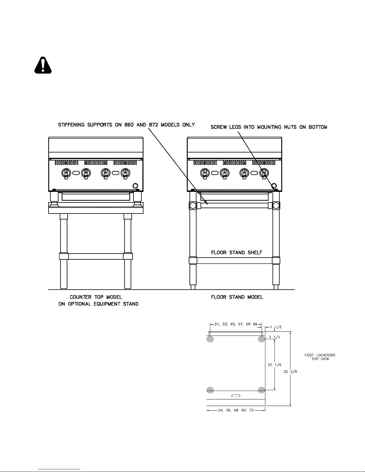
LEVELING UNIT
This griddle is supplied with 4 feet or fl oor stand legs which must be screwed into the body.
Unit must be level. Level unit by adjusting the (4) feet which have an adjustment of 1-3/4" for
accurate and perfect line-up with other units.
DO NOT INST ALL WITHOUT ATTACHING FEET OR SUPPLIED STAND LEGS AND
SHELF - DO NOT REMOVE FEET.
Caster Kits: Casters can be used with fl oor
stand models or optional equipment stand.
For installation, carefully mark and cut off from
the bottom of each leg using a straight cutting
saw and de-burr the inside tube wall prior to
installing the caster. Cut leg should measure
19" tube length, not overall length. Casters add
about 6-1/4" of height to the unit. Be sure to
use approved strain relief means for protecting
gas line connection. If an appliance is equipped
with casters and is gas connected with a quick
connect coupling, all personnel must be aware
that there is a restraint on the appliance and if
disconnected for service or cleaning it must be
reconnected as originally installed prior to use.
6
GAS PIPING
Gas piping shall be of such size and so installed as to provide a supply of gas suffi cient to meet
the full gas input of the appliance. If the appliance is to be connected to existing piping, it shall
be checked to determine if it has adequate capacity . Joint compound shall be used sparingly and
only on the male threads of the pipe joints. Such compounds shall be resistant to the action of
L.P. gases. WARNING: Any loose dirt or metal particles which are allowed to enter the gas lines
on this appliance will damage the valve and affect its operation. When installing this appliance,
all pipe and fi ttings must be free from all internal loose dirt.
GAS PRESSURE REGULATOR
A convertible pressure regulator is provided with each griddle. It should be connected to the
inlet pipe at the rear of the unit. The gas supply is then connected to it. The supply pressure to
the regulator is not to exceed 1/2 psig. All units are shipped for use with natural gas. M and T
Series Models are shipped set for 5" water column manifold pressure. TS and TSCHS Series
Models are shipped set for 4" water column manifold pressure.
MANUAL SHUT OFF VALVE
A manual shut off valve should be installed upstream from the manifold and within six feet of
the griddle.
CONNECTING GAS SUPPLY LINE
The gas inlet of the griddle is sealed at the factory to prevent entry of dirt. Do not remove this
seal until the actual connection is made to the gas supply line.
PROPANE GAS - CONVERSION
This griddle is equipped with fi xed orifi ce hoods and is shipped from the factory for use with
natural gas. To convert to propane gas install the orifi ce hoods located behind the front panel
as follows:
1. Remove the front panel by removing the
screws located on the front and bottom.
2. Remove the burner mounting screws in
the center of the combustion chamber
access covers.
3. Slide the burners back off the orifi ce
hoods.
4. Remove the natural gas orifi ce hoods and
install the propane orifi ce hoods.
5. Slide the burners back over the orifi ce
hoods and reinstall the burner mounting
screws.
6. Reinstall the front panel.
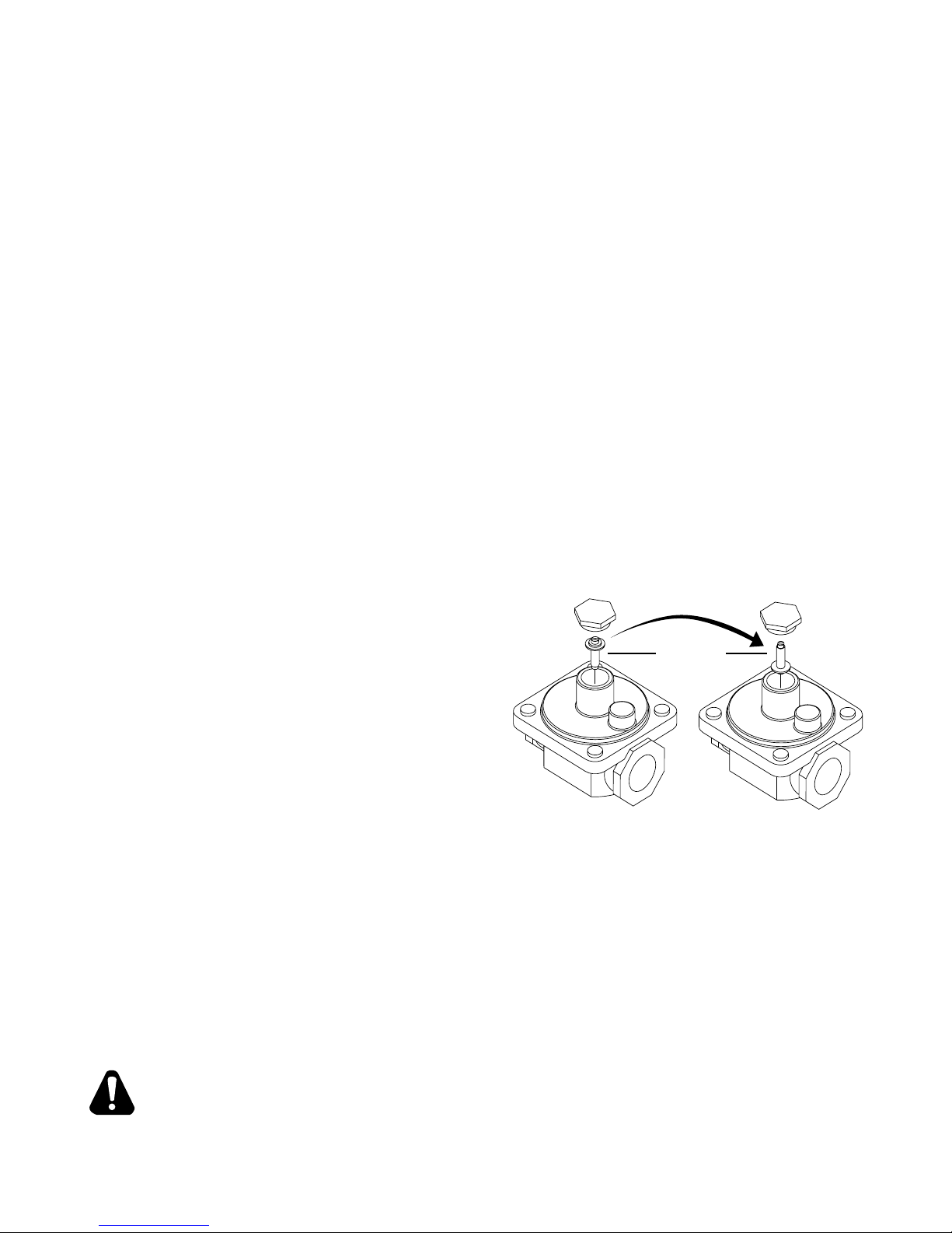
7. Set the pressure regulator to 10" (25.4cm) water column by removing the slotted or hex
cap from the center of the regulator. Invert the plug and reinstall. The letters "LP" will now
be visible on the plug. Reinstall the cap. An 1/8" pipe plug is located on the manifold for
attaching a pressure gauge.
Natural
PLUG
IL1199
Propane / LP
Regulator
CHECKING FOR GAS LEAKS
Check entire piping system for leaks. Soap and water solution or other material acceptable for
the purpose, shall be used in locating gas leakage.
Matches, candle fl ame or other sources of ignition shall not be used for locating
CAUTION
gas leaks.
7
CAUTION
PILOT FLAME ADJUSTMENT
The griddles are equipped with standing pilots and should be lit immediately after the gas is
turned on.
MANUAL VALVE AND THROTTLING CONTROL MODELS
Adjust the fl ame as low as possible while still providing immediate burner ignition when
the control knob is turned to high.
SNAP ACTION THERMOSTAT AND CHROME SURFACE MODELS
Adjust the pilot so approximately 3/8" of the thermocouple tip is surrounded by
the pilot fl ame.
LIGHTING INSTRUCTIONS
When the griddle is fi rst lit, it will smoke until the preservative oils and impurities are burned
off. The griddles are equipped with standing pilots and should be lit immediately after the gas
is turned on. The Unit should be properly leveled prior to lighting.
DO NOT ATTEMPT TO LIGHT YOUR PILOT BURNER IF YOU EXPERIENCE A
STRONG GAS ODOR.
MANUAL VALVE AND THROTTLING CONTROL MODELS
1. Turn off the main valve to the unit and wait 5 minutes to clear gas.
2. Turn off all knobs and pilot valves.
3. Turn on main valve to unit and light all pilots.
4. Turn burner knobs to desired position.
5. To turn burners off, turn knobs to off.
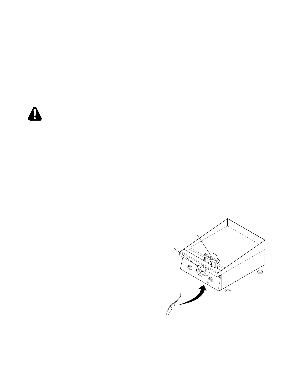
SNAP ACTION THERMOSTAT AND CHROME SURFACE MODELS
1. Turn all knobs and power switch to "OFF" and wait 5 minutes to clear gas.
Remove any grease trays.
2. Put lighter under the front of the griddle. FIG 1
3. Look through large hole in front panel.
4. Move Lighter up to the pilot.
5. Put your other hand under the front of
the griddle and press the button on the
saftey valve.
6. Once the pilot is lit, remove the lighter and
continue to press the button for at least
30 seconds. You only need to light one
pilot.
7. Once pilot remains lit, turn the power switch
"ON" and turn all knobs to the "ON" position.
This will light all other pilots.
8. To turn burners off, turn off power
switch.
Saftey Valve
Pilot
IL1200
FIG 1, Place Lighter under griddle
8

CAUTION
BURNER AIR SHUTTER ADJUSTMENT
The burner air shutter has a locking screw on the bottom side of the venturi. Loosen this screw
to make any adjustment and tighten the screw to lock the air shutter in place after adjustment
is complete. Any adjustment must be made when the burner is at full input before the control
temperature setting has been satisfi ed.
1. Turn the control knob to the highest position and observe the burner fl ame.
2. Slowly decrease the air shutter opening until the fl ame is a soft blue with yellow tips, then
increase the opening until the yellow tips disappear and the fl ame is a hard blue.
3. Do not open the shutter to a point where the fl ame is unstable or lifting from the burner
surface. The fl ame must be steady and even across the entire burner.
The following was set at the factory and the adjustment should only be made
by an authorized installer and only if you are experiencing this specifi c
problem.
BYPASS ADJUSTMENT ON THROTTLING CONTROL MODELS ONLY
Throttling control models have a minimum fl ame setting that provides a steady uniform fl ame
across the burner when the control heat setting has been satisfi ed.
1. Set the control at the maximum setting and wait for the burner fl ame to throttle back.
2. Turn the dial to the 200 degree setting. A small steady fl ame should be visible on all the
burner ports. This fl ame should be approximately 1/8" high.
3. An adjustment screw is located either on the front or side of the control housing.
4. Turn clockwise to decrease the fl ame height; turn counterclockwise to increase the fl ame
CAUTION
ELECTRICAL CONNECTION FOR SNAP ACTION AND CHROME SURFACE
MODELS ONLY
Snap action and chrome surface griddles are equipped with a three-prong grounding plug. The
unit is designed for use on a 120 volt 15 amp 50/60 cycle AC single-phase circuit only. For
protection against electrical shock, the unit must be plugged directly into a properly grounded
three-prong receptacle. Do not cut or remove the grounding prong from this plug.
Do not connect to any other type of current or serious damage will occur.
OPERATING INSTRUCTIONS
SEASONING THE GRIDDLE HEATING SURFACE (NON-CHROME SURFACES)
Clean the griddle surface thoroughly. After the griddle has been thoroughly cleaned, it should
be seasoned to prevent food from sticking. Before using and after each thorough scouring,
season the griddle heating surface in the following manner:
1. Turn the temperature control dial to 350°F (174.0°C).
2. Using a clean cloth, not a spatula, spread a thin fi lm of cooking oil or shortening over the
griddle cooking surface. This fi lm should remain on the hot griddle surface 1/2 hour.
3. Remove excess shortening and wipe clean.
4. Apply another fi lm of cooking oil over the hot cooking area for another 1/2 hour, and again
remove excess shortening and wipe clean. The griddle surface should now be ready for
use.
Even with careful seasoning food may , to some extent, stick to the griddle cooking
CAUTION
surface until griddle plate is "broken in."
COOKING
Set the dial knob to the setting desired. After a 30 minute (minimum) preheating period, the
griddle will automatically maintain the selected temperature.
9
GRIDDLE CARE (NON-CHROME SURFACES)
It takes very little time and effort to keep the griddle attractive and performing at top effi ciency.
If grease is permitted to accumulate, it will form a gummy cake and then carbonize into a
hard substance which is extremely diffi cult to remove. To prevent this condition, the following
suggestions for cleanliness should be followed:
1. After each use, scrape the griddle with a scraper or fl exible spatula to remove excess
grease and food. A waste drawer is provided for the scrapings. If there is an accumulation
of burned-on grease and food, the griddle should be thoroughly scoured and reseasoned.
Use pumice or griddle stone while the griddle is warm. Do not use steel wool because of
the danger of steel slivers getting into the food.
2. Use a clean cloth and good non-abrasive cleaner to clean the stainless steel body of the
griddle. Wipe the control panel front with a soft cloth.
3. At least once a day, remove the waste drawer and wash in the same way as an ordinary
cooking utensil. The drawer is removed by pulling forward and out.
GRIDDLE CARE (CHROME SURFACES)
(Chrome surface griddles are marked with "CHS" at the end of the model number designation on
the nameplate.) It takes very little time and effort to keep this Industrial Chrome griddle surface
sparkling clean and performing at top effi ciency. DO NOT allow grease to accumulate as it
will carbonize and become diffi cult to remove. To prevent this condition, the following cleaning
suggestions should be followed:
CAUTION
CAUTION
1. Remove excess oil and food regularly with a 4" (100mm) wide razor sharp type scraper
and wipe surface with a damp cloth if desired.
2. Following the scraping, for end of the day cleaning, a damp cloth and a non-silicated, nonabrasive, non-chlorinated cleaner such as Bon-Ami may be used to wipe surface clean,
followed by wiping with clean wet cloth.
3. Follow steps 2 and 3 from Griddle Care (Non-Chrome Surfaces).
CAUTION
1. Never use pumice, griddle stones, or abrasives on the surface.
2. Never strike the griddle surface with a sharp instrument or spatula edge.
3. Never use steel wool.
4. Never use commercial liquid grill cleaner on the griddle surface.
5. Abusing the surface voids the warranty.
WASTE DRAWER
A waste drawer is located at the front and can be removed from the front for cleaning by pulling
drawer forward. This drawer should be checked and emptied when necessary or at least once
per day.
EXERCISE EXTREME CARE IN HANDLING THE WASTE DRAWER CONTAINING
HOT GREASE.
OVERNIGHT SHUTDOWN
MANUAL VALVE AND THROTTLING CONTROL MODELS
Turn knobs to the off position to turn burners off.
SNAP ACTION AND CHROME SURFACE MODELS
Turn knobs to the lowest setting and turn power switch off.
10

CHROME GRIDDLE SURFACE LIMITED WARRANTY EXCLUSIONS
Your chrome griddle has been designed to give you many years of cooking reliability and
requires minimum maintenance to keep the chrome surface in its original condition. All chrome
griddle surfaces are warranted for a period of 5 years against manufacturing defects to the
original owner from the date of installation. This limited warranty is void if it is determined by
Star Manufacturing International Incorporated or one of its authorized representatives that the
chrome surface has been misused or abused or subjected to the following situations:
1. Improperly installed.
2. By-pass adjustments not set properly on gas units allowing the appliance to overheat and
discolor the chrome surface. (See by-pass adjustment section.)
3. The misuse of any instrument or tool which scratches or makes indentations in the surface
which could cause the surface to peel, fl ake, or chip off.
4. The use of any chemical or abrasive cleaning solution, griddle brick, stone, screen or
other cleaning products which could damage and affect the performance of the chome
surface.
5. The neglect of daily routine maintenance to the chrome surface.
11

SYMBOLE DE SÉCURITÉ
CONSERVEZ CE MANUEL POUR RÉFÉRENCE FUTURE
L’utilisation de toute pièce autre que les pièces d’origine STAR dégage le fabricant de toute responsabilité.
Star se réserve le droit de changer les spécifi cations et la conception du produit
sans préavis. Ces changements ne donnent pas le droit à l’acheteur d’obtenir
les changements, améliorations, ajouts ou remplacements correspondants pour
l’équipement acheté préalablement.
Dû aux modifi cations périodiques de dessins, méthodes, procédures, règles
et régulations, les spécifi cations contenues dans ce manuel sont susceptibles
de changer sans préavis. Quoique STAR Manufacturing exerce la bonne foi de
fournir le renseignement correct, STAR n’est pas responsable pour les erreurs
ou les omissions dans le renseignement pourvu ou les conclusions tirées à la
suite de l’utilisation des spécifi cations. En utilisant le renseignement pourvu,
l’utilisateur assume tous les risques en relation avec telle utilisation.
Ces symboles sont utilisés pour souligner à l’utilisateur les
instructions d’utilisation ou d’entretien importantes contenues
dans le manuel qui accompagne l’appareil.
AVIS
ENTRETIEN ET RÉPARATIONS
Contactez votre détaillent local pour les réparations ou l’entretien requis. Assurez-vous d’avoir
le numéro de modèle, le numéro de série, le voltage et la date d’achat pour un service plus
rapide. Entrez l’information requise ci-dessous pour référence rapide.
Agent de service autorisé
N° de modèle
N° de série
Voltage
Date d’achat
Voir la liste pourvue avec l’appareil
Ou
Pour une liste mise à jour voir :
Site web : www.star-mfg.com
Courriel : Service@star-mfg.com
12
 Loading...