

Star 860TSCHSA Operators Manual
Star
Manufacturing
International Inc.
Installation and
Operating Instructions
10 Sunnen Drive
St. Louis, MO 63143
Phone: (314) 678-6303
Fax: (314) 781-2714
Instructions d’installation
et d’opération
2M-Z16558 Rev. B 11/05/2013
ULTRA-MAX™ GAS GRIDDLE MODELS
GRILS A GAZ ULTRA-MAX MODELES
824MA 824TA 824TSA 824TCHSA 824TSCHSA
836MA 836TA 836TSA 836TCHSA 836TSCHSA
848MA 848TA 848TSA 848TCHSA 848TSCHSA
860MA 860TA 860TSA 860TCHSA 860TSCHSA
872MA 872TA 872TSA 872TCHSA 872TSCHSA
WARNING: Improper installation,
adjustment, alteration, service or
maintenance can cause property
damage, injury or death. Read the
installation, operating and maintenance
instructions thoroughly before installing
or servicing this equipment.
AVERTISSEMENT: L’installation inexacte, le réglage,
le changement, le service ou l’entretien peuvent
causer des dégats matériels, des dommages ou la
mort. Lisez les instructions d’installation, d’opération
et d’entretien complètement avant d’installer ou
entretenir ce matériel.
FOR YOUR SAFETY: Do not store or
use gasoline or other ammable vapors or
liquids in the vicinity of this or any other
appliance.
POUR VOTRE SÛRETÉ: N’enregistrez pas ou
n’utilisez pas l’essence ou d’autres vapeurs ou
liquides inammables à proximité de ceci ou d’aucun
autre appareil.
WARNING: This appliance shall be
installed in accordance with current
regulations and used only in wellventilated space. Refer to instructions
before installing and using this
appliance.
AVERTISSEMENT: Cet appareil sera installé selon
des règlements actuels et utilisé seulement dans
l’espace bien-aéré. Référez-vous aux instructions
avant d’installer et utiliser cet appareil.
In addition, there should be posted, in a
prominent location, detailed instructions
to be followed in the event the operator
smells gas. Obtain the instructions from
the local gas supplier.
En outre, là devrait être signalé, dans un
emplacement en avant, des instructions détaillées
d’être suivi en cas que l’opérateur sent le gaz.
Obtenez les instructions du fournisseur local de gaz.

Please record the model number, serial number, voltage and purchase date in the area below and have it ready when
SAFETY SYMBOL
Using any part other than genuine Star factory supplied parts relieves the
manufacturer of all liability.
Star reserves the right to change specications and product design without
notice. Such revisions do not entitle the buyer to corresponding changes,
improvements, additions or replacements for previously purchased
equipment.
Due to periodic changes in designs, methods, procedures, policies and
regulations, the specications contained in this sheet are subject to change
without notice. While Star International Holdings Inc., Company exercises
good faith efforts to provide information that is accurate, we are not
responsible for errors or omissions in information provided or conclusions
reached as a result of using the specications. By using the information
provided, the user assumes all risks in connection with such use.
These symbols are intended to alert the user to the presence of
important operating and maintenance instructions in the manual
accompanying the appliance.
RETAIN THIS MANUAL FOR FUTURE REFERENCE
NOTICE
MAINTENANCE AND REPAIRS
Contact your local authorized service agent for service or required maintenance.
you call to ensure a faster service.
Model No.
Serial No.
Voltage
Purchase Date
Authorized Service Agent Listing
Reference the listing provided with the unit
or
for an updated listing go to:
Website: www.star-mfg.com
E-mail Service@star-mfg.com
Service Help Desk
Business 8:00 am to 4:30 p.m. Central Standard Time
Hours:
Telephone: (314) 678-6303
Fax: (314) 781-2714
E-mail Parts@star-mfg.com
Service@star-mfg.com
Warranty@star-mfg.com
Website: www.star-mfg.com
Mailing Address: Star International Holdings Inc., Company
10 Sunnen Drive
St. Louis, MO 63143
U.S.A
2
22
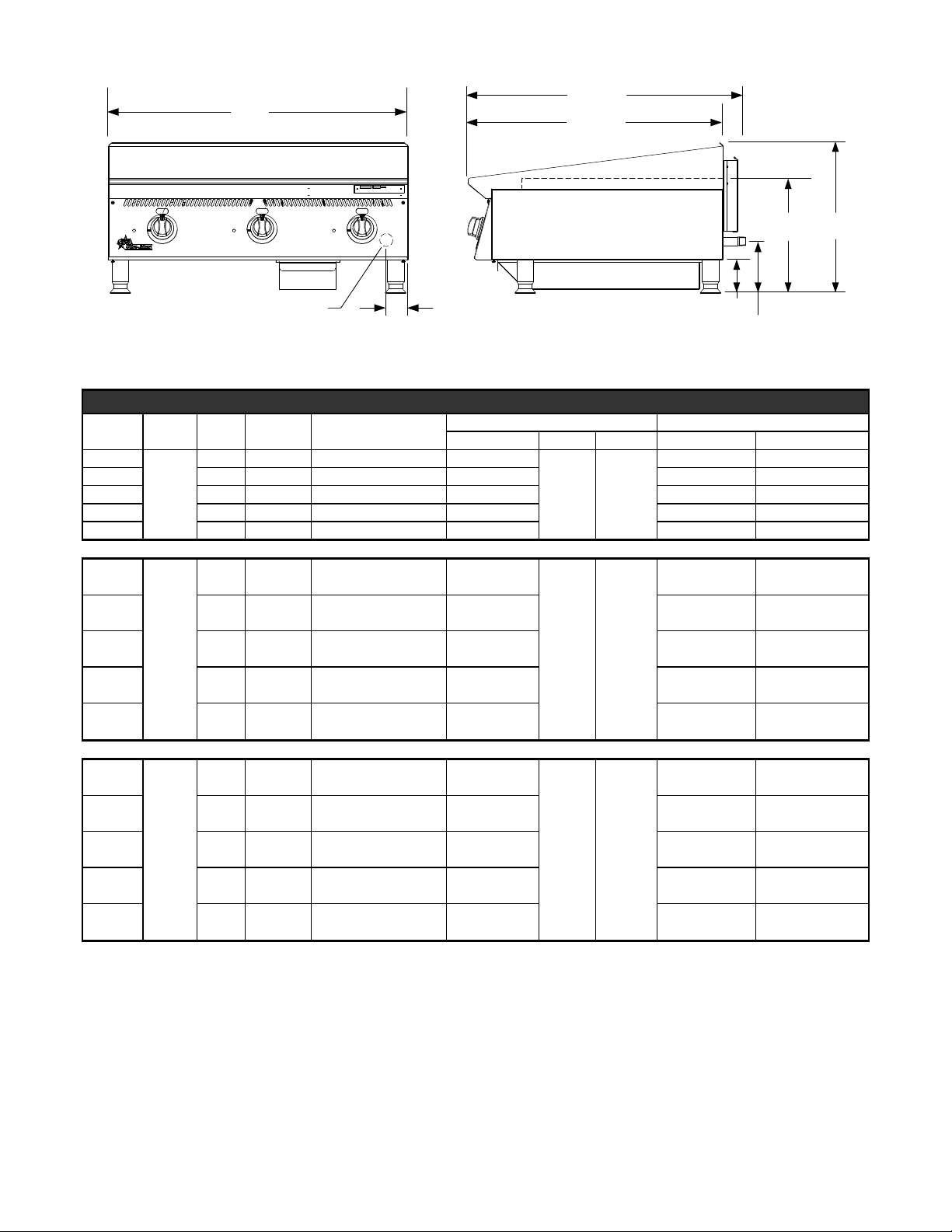
32 3/8”
Width
(82.3 cm)
30 5/8”
(82.3 cm)
GAS INLET
2 3/16”
(5.5 cm)
13 9/16”
(34.4cm)
4”
7 7/16”
(13.8cm)
18”
(45.8cm)
IL2585
SPECIFICATIONS
Model Type Controls BTUH Griddle Area
824MA
836MA 3 90,000 860 sq. in. (5545 sq. cm) 36” (91.4cm) 321lbs (145.4kg) 366lbs (165.8kg)
848MA 4 120,000 1146 sq. in (7397 sq. cm) 48” (122cm) 428lbs (193.3kg) 488lbs (221.1kg)
860MA 5 150,000 1433 sq in (9242 sq cm) 60” (152.4cm) 535lbs (242.4kg) 610lbs (276.4kg)
Manual
Valve
(pilot)
2 60,000 573 sq in (3697sq. cm) 24” (61cm)
872MA 6 180,000 1719 sq in (11091 sq cm) 72” (182.9cm) 642lbs (290.9kg) 732lbs (331.7kg)
824TA
2 60,000 573 sq in (3697sq. cm) 24” (61cm)
836TA 3 90,000 860 sq. in. (5545 sq. cm) 36” (91.4cm) 321lbs (145.4kg) 366lbs (165.8kg)
848TA 4 120,000 1146 sq. in (7397 sq. cm) 48” (122cm) 428lbs (193.3kg) 488lbs (221.1kg)
T-Stat
(pilot)
Dimensions Approx Weight
Width Depth Height Installed Shipping
214lbs (97kg) 244lbs (110.6kg)
32 3/8”
(82.2cm)
18”
(45.7cm)
214lbs (97kg) 244lbs (110.6kg)
32 3/8”
(82.2cm)
18”
(45.7cm)
860TA 5 150,000 1433 sq in (9242 sq cm) 60” (152.4cm) 535lbs (242.4kg) 610lbs (276.4kg)
872TA 6 180,000 1719 sq in (11091 sq cm) 72” (182.9cm) 642lbs (290.9kg) 732lbs (331.7kg)
824TSA,
TSCHSA
836TSA,
TSCHSA
848TSA,
TSCHSA
860TSA,
TSCHSA
872TSA,
TSCHSA
Thermal
Spark
(no pilot)
2 80,000 573 sq in (3697sq. cm) 24” (61cm)
214lbs (97kg) 244lbs (110.6kg)
3 120,000 860 sq. in. (5545 sq. cm) 36” (91.4cm) 321lbs (145.4kg) 366lbs (165.8kg)
4 160,000 1146 sq. in (7397 sq. cm) 48” (122cm) 428lbs (193.3kg) 488lbs (221.1kg)
32 3/8”
(82.2cm)
18”
(45.7cm)
5 200,000 1433 sq in (9242 sq cm) 60” (152.4cm) 535lbs (242.4kg) 610lbs (276.4kg)
6 240,000 1719 sq in (11091 sq cm) 72” (182.9cm) 642lbs (290.9kg) 732lbs (331.7kg)
33

CAUTION
GENERAL INSTALLATION DATA
This equipment is designed and sold for commercial use only by personnel trained and experienced
in its operation and is not sold for consumer use in and around the home nor for use directly by the
general public in food service locations.
Before using your new equipment, read and understand all the instructions & labels associated with
the unit prior to putting it into operation. Make sure all people associated with its use understand the
units operation & safety before they use the unit.
Ultra-Max series griddles are equipped for use on either natural or propane gas. All units are shipped
for natural gas and can easily be converted to propane. See Propane Gas - Conversion.
-IMPORTANT-
Be sure to remove all paper protection and packing material from unit prior to
lighting. Remove the protective plastic from the griddle plate and thoroughly
clean the unit's exterior surfaces.
KEEP THE APPLIANCE AREA FREE AND CLEAR FROM COMBUSTIBLES! For
use on non-combustible countertops only. Combustible and non-combustible
material must be at least 48" (120cm) from the top of the appliance and at
least 6" (16cm) from the sides and back. Adequate clearance should also be
provided for proper operation and servicing.
The installation of the Appliance must conform to the NATIONAL FUEL GAS
CODE "ANSI Z223.1 - LATEST EDITION" AND ALL LOCAL GAS COMPANY
RULES AND REGULATIONS.
IN CANADA INSTALLATION SHALL BE IN ACCORDANCE WITH THE
CURRENT CAN/CGA-B149.1 NATURAL GAS INSTALLATION CODE OR
CAN/CGA-B149.2 PROPANE INSTALLATION CODE AND LOCAL CODES
WHERE APPLICABLE.
NOTICE
When this appliance is installed with casters, it must be installed with the casters supplied, a connector
complying with either ANSI Z21.69 or CAN/CGA-6.16 and a quick-disconnect device complying with
either ANSI Z21.41 or CAN1-6.9. It must also be installed with restraining means to guard against
transmission of strain to the connector.
For your protection, we recommend a qualied installing agency install this appliance.
They should be familiar with gas installations and your local gas requirements. In any
case, your gas company should be called to approve the nal installation.
This appliance, its pressure regulator and its individual shutoff valve must be disconnected from the
gas supply piping system during any pressure testing of that system at test pressures in excess of 1/2
PSIG. This appliance and its pressure regulator must be isolated from the gas supply piping system by
closing its individual manual shutoff valve during any pressure testing of the gas supply piping system
at test pressures equal to or less than 1/2 PSIG.
EXHAUST CANOPY
Griddles inherently create a good deal of heat and smoke and should be installed under an efcient
exhaust hood with ame proof lters. A vertical distance of not less than 48" shall be provided between
the top of the appliance and lters or any other combustible material. Exhaust installation must
conform to local codes.
CAUTION
AIR SUPPLY: Provisions for adequate air supply must be provided.
AIR INTAKES IN BOTTOM
Air for combustion enters from the bottom of the unit. Do not obstruct this area.
44

SCREW LEGS INTO
MOUNTING NUTS ON BOTTOM
FLOOR STAND SHELF
STIFFENING SUPPORTS FOR
860 & 872 MODELS ONLY
FLOOR STAND MODELCOUNTER TOP MODEL
ON OPTIONAL EQUIPMENT STAND
IL2586
CAUTION
LEVELING UNIT
This griddle is supplied with 4 feet or oor stand legs which must be screwed into the body. After
the griddle is in its nal position, adjust the legs to create 1/8 inch slant from back to front. This will
allow the grease to run into the grease gutter and provide the proper combustion air for the burners.
Adjusting the (4) feet which have an adjustment of 1-3/4" for accurate and perfect line-up with other
units.
DO NOT INSTALL WITHOUT ATTACHING FEET OR SUPPLIED STAND LEGS
AND SHELF - DO NOT REMOVE FEET.
Caster Kits: Casters can be used with oor
stand models or optional equipment stand.
For installation, carefully mark and cut off from
the bottom of each leg using a straight cutting
saw and de-burr the inside tube wall prior to
installing the caster. Cut leg should measure
19" tube length, not overall length. Casters
add about 6-1/4" of height to the unit. Be
sure to use approved strain relief means for
protecting gas line connection. If an appliance
is equipped with casters and is gas connected
with a quick connect coupling, all personnel
must be aware that there is a restraint on the
appliance and if disconnected for service or
cleaning it must be reconnected as originally
installed prior to use.
55
GAS PIPING
PLUG
IL1199
Natural
Regulator
Propane / LP
Gas piping shall be of such size and so installed as to provide a supply of gas sufcient to meet the
full gas input of the appliance. If the appliance is to be connected to existing piping, it shall be checked
to determine if it has adequate capacity. Joint compound shall be used sparingly and only on the male
threads of the pipe joints. Such compounds shall be resistant to the action of L.P. gases. WARNING:
Any loose dirt or metal particles which are allowed to enter the gas lines on this appliance will damage
the valve and affect its operation. When installing this appliance, all pipe and ttings must be free from
all internal loose dirt.
GAS PRESSURE REGULATOR
A convertible pressure regulator is provided with each griddle. It should be connected to the inlet pipe
at the rear of the unit. The gas supply is then connected to it. The supply pressure to the regulator is
not to exceed 1/2 psig. If the gas pressure going to the regulator on the griddle exceeds 1/2 PSIG
then another regulator must be installed to lower the pressure going to it. This second regulator is not
supplied with the griddle and is the customers responsibility. All units are shipped for use with natural
gas. MA and TA Series Models are shipped set for 5" water column manifold pressure. TSA and
TSCHSA Series Models are shipped set for 5" water column manifold pressure.
MANUAL SHUT OFF VALVE
A manual shut off valve should be installed upstream from the manifold and within six feet of the
griddle. The shut-off valve is not supplied with the griddle and is the customers responsibility.
CONNECTING GAS SUPPLY LINE
The gas inlet of the griddle is sealed at the factory to prevent entry of dirt. Do not remove this seal until
the actual connection is made to the gas supply line.
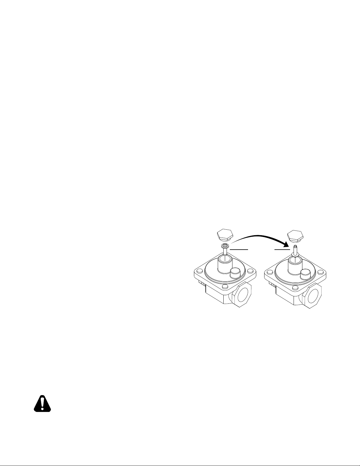
PROPANE GAS - CONVERSION
This griddle is equipped with xed orice hoods and is shipped from the factory for use with natural
gas. To convert to propane gas install the orice hoods located behind the front panel as follows:
1. Remove the front panel by removing the
screws located on the front and bottom.
2. Remove the burner mounting screws in the
center of the combustion chamber access
covers.
3. Slide the burners back off the orice hoods.
4. Remove the natural gas orice hoods and
install the propane orice hoods.
5. Slide the burners back over the orice hoods
and reinstall the burner mounting screws.
6. Reinstall the front panel.
7. Set the pressure regulator to 10" (25.4cm)
water column by removing the slotted or
hex cap from the center of the regulator.
Invert the plug and reinstall. The letters "LP"
will now be visible on the plug. Reinstall the cap. An 1/8" pipe plug is located on the manifold for
attaching a pressure gauge.
CHECKING FOR GAS LEAKS
Check entire piping system for leaks. Soap and water solution or other material acceptable for the
purpose, shall be used in locating gas leakage.
CAUTION
Matches, candle ame or other sources of ignition shall not be used for
locating gas leaks.
66
PILOT FLAME ADJUSTMENT
The griddles are equipped with standing pilots and should be lit immediately after the gas is turned on.
MANUAL VALVE AND THROTTLING CONTROL MODELS
Adjust the ame as low as possible while still providing immediate burner ignition when the control
knob is turned to high.
LIGHTING INSTRUCTIONS
When the griddle is rst lit, it will smoke until the preservative oils and impurities are burned off.
The griddles are equipped with standing pilots and should be lit immediately after the gas is turned
on. Snap Action giddles do not have a standing pilot and do not require lighting. The Unit should
be properly leveled prior to lighting, with the rear of the griddle slightly higher than the front to allow
grease to roll off and ue gasses to escape out the rear..
DO NOT ATTEMPT TO LIGHT YOUR PILOT BURNER IF YOU EXPERIENCE A
STRONG GAS ODOR.
CAUTION
MANUAL VALVE AND THROTTLING CONTROL MODELS
1. Turn off the main valve to the unit and wait 5 minutes to clear gas.
2. Turn off all knobs and pilot valves.
3. Turn on main valve to unit and light all pilots.
4. Turn burner knobs to desired position.
5. To turn burners off, turn knobs to off.
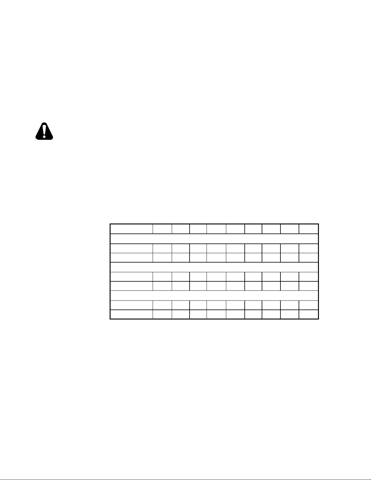
ORIFICE ELEVATION COMPENSATION CHART
Orice @ sea level 2000 3000 4000 5000 6000 7000 8000 9000 10000
Manual Control Gas Griddles: 824ma thru 872MA
NAT 41 42 42 42 43 43 44 44 45 46
LP 52 52 53 53 53 53 53 54 54 54
Thermostatic Conrol Gas Griddles: 824TA thru 872TA
NAT 38 39 40 41 41 42 42 43 43 44
LP 52 52 53 53 53 53 53 54 54 54
Snap Action Gas Griddles: 824TSA thru 872TSA
NAT 34 35 36 36 37 37 38 39 40 42
LP 49 50 50 50 51 51 51 52 52 52
77
CAUTION
BURNER AIR SHUTTER ADJUSTMENT
The burner air shutter has a locking screw on the bottom side of the venturi. Loosen this screw
to make any adjustment and tighten the screw to lock the air shutter in place after adjustment
is complete. Any adjustment must be made when the burner is at full input before the control
temperature setting has been satised.
1. Turn the control knob to the highest position and observe the burner ame.
2. Slowly decrease the air shutter opening until the ame is a soft blue with yellow tips, then increase
the opening until the yellow tips disappear and the ame is a hard blue.
3. Do not open the shutter to a point where the ame is unstable or lifting from the burner surface.
The ame must be steady and even across the entire burner.
The following was set at the factory and the adjustment should only be made
by an authorized installer and only if you are experiencing this specic
problem.
BYPASS ADJUSTMENT ON THROTTLING CONTROL MODELS ONLY
Throttling control models have a minimum ame setting that provides a steady uniform ame across
the burner when the control heat setting has been satised.
1. Set the control at the maximum setting and wait for the burner ame to throttle back.
2. Turn the dial to the 200 degree setting. A small steady ame should be visible on all the burner
ports. This ame should be approximately 1/8" high.
3. An adjustment screw is located either on the front or side of the control housing.
4. Turn clockwise to decrease the ame height; turn counterclockwise to increase the ame
CAUTION
CAUTION
ELECTRICAL CONNECTION FOR SNAP ACTION AND CHROME SURFACE
MODELS ONLY
Snap action and chrome surface griddles are equipped with a three-prong grounding plug. The unit
is designed for use on a 120 volt 15 amp 50/60 cycle AC single-phase circuit only. For protection
against electrical shock, the unit must be plugged directly into a properly grounded three-prong
receptacle. Do not cut or remove the grounding prong from this plug.
Do not connect to any other type of current or serious damage will occur.
OPERATING INSTRUCTIONS
SEASONING THE GRIDDLE HEATING SURFACE (NON-CHROME SURFACES)
Clean the griddle surface thoroughly. After the griddle has been thoroughly cleaned, it should be
seasoned to prevent food from sticking. Before using and after each thorough scouring, season the
griddle heating surface in the following manner:
1. Turn the temperature control dial to 350°F (174.0°C).
2. Using a clean cloth, not a spatula, spread a thin lm of cooking oil or shortening over the griddle
cooking surface. This lm should remain on the hot griddle surface 1/2 hour.
3. Remove excess shortening and wipe clean.
4. Apply another lm of cooking oil over the hot cooking area for another 1/2 hour, and again remove
excess shortening and wipe clean. The griddle surface should now be ready for use.
Even with careful seasoning food may, to some extent, stick to the griddle cooking
surface until griddle plate is "broken in."
COOKING
Set the dial knob to the setting desired. After a 30 minute (minimum) preheating period, the griddle
will automatically maintain the selected temperature.
88
GRIDDLE CARE (NON-CHROME SURFACES)
It takes very little time and effort to keep the griddle attractive and performing at top efciency. If
grease is permitted to accumulate, it will form a gummy cake and then carbonize into a hard substance
which is extremely difcult to remove. To prevent this condition, the following suggestions for
cleanliness should be followed:
1. After each use, scrape the griddle with a scraper or exible spatula to remove excess grease and
food. A waste drawer is provided for the scrapings. If there is an accumulation of burned-on grease
and food, the griddle should be thoroughly scoured and reseasoned. Use pumice or griddle stone
while the griddle is warm. Do not use steel wool because of the danger of steel slivers getting into
the food.
2. Use a clean cloth and good non-abrasive cleaner to clean the stainless steel body of the griddle.
Wipe the control panel front with a soft cloth.
3. At least once a day, remove the waste drawer and wash in the same way as an ordinary cooking
utensil. The drawer is removed by pulling forward and out.
GRIDDLE CARE (CHROME SURFACES)
(Chrome surface griddles are marked with "CHS" at the end of the model number designation on the
nameplate.) It takes very little time and effort to keep this Industrial Chrome griddle surface sparkling
clean and performing at top efciency. DO NOT allow grease to accumulate as it will carbonize and
become difcult to remove. To prevent this condition, the following cleaning suggestions should be
followed:
1. Remove excess oil and food regularly with a 4" (100mm) wide razor sharp type scraper and wipe
surface with a damp cloth if desired.
2. Following the scraping, for end of the day cleaning, a damp cloth and a non-silicated, non-abrasive,
non-chlorinated cleaner such as Bon-Ami may be used to wipe surface clean, followed by wiping
with clean wet cloth.
3. Follow steps 2 and 3 from Griddle Care (Non-Chrome Surfaces).
CAUTION
CAUTION
CAUTION
1. Never use pumice, griddle stones, or abrasives on the surface.
2. Never strike the griddle surface with a sharp instrument or spatula edge.
3. Never use steel wool.
4. Never use commercial liquid grill cleaner on the griddle surface.
5. Abusing the surface voids the warranty.
WASTE DRAWER
A waste drawer is located at the front and can be removed from the front for cleaning by pulling drawer
forward. This drawer should be checked and emptied when necessary or at least once per day.
EXERCISE EXTREME CARE IN HANDLING THE WASTE DRAWER CONTAINING
HOT GREASE.
OVERNIGHT SHUTDOWN
MANUAL VALVE AND THROTTLING CONTROL MODELS
Turn knobs to the off position to turn burners off.
SNAP ACTION AND CHROME SURFACE MODELS
Turn knobs to the lowest setting and turn power switch off.
99
 Loading...