

Page 1

Star
Manufacturing
International Inc.
Installation and
Operating Instructions
10 Sunnen Drive
St. Louis, MO 63143
Phone: (314) 678-6303
Fax: (314) 781-2714
Instructions d’installation
et d’opération
2M-Z4877 Rev. H 2/28/2012
ULTRA-MAX™ GAS GRIDDLE MODELS
GRILS A GAZ ULTRA-MAX MODELES
824M 824T 824TS 824TCHS 824TSCHS
836M 836T 836TS 836TCHS 836TSCHS
848M 848T 848TS 848TCHS 848TSCHS
860M 860T 860TS 860TCHS 860TSCHS
872M 872T 872TS 872TCHS 872TSCHS
WARNING: Improper installation,
adjustment, alteration, service or
maintenance can cause property
damage, injury or death. Read the
installation, operating and maintenance
instructions thoroughly before installing
or servicing this equipment.
AVERTISSEMENT: L’installation inexacte, le réglage,
le changement, le service ou l’entretien peuvent
causer des dégats matériels, des dommages ou la
mort. Lisez les instructions d’installation, d’opération
et d’entretien complètement avant d’installer ou
entretenir ce matériel.
FOR YOUR SAFETY: Do not store or
use gasoline or other ammable vapors or
liquids in the vicinity of this or any other
appliance.
POUR VOTRE SÛRETÉ: N’enregistrez pas ou
n’utilisez pas l’essence ou d’autres vapeurs ou
liquides inammables à proximité de ceci ou d’aucun
autre appareil.
WARNING: This appliance shall be
installed in accordance with current
regulations and used only in wellventilated space. Refer to instructions
before installing and using this
appliance.
AVERTISSEMENT: Cet appareil sera installé selon
des règlements actuels et utilisé seulement dans
l’espace bien-aéré. Référez-vous aux instructions
avant d’installer et utiliser cet appareil.
In addition, there should be posted, in a
prominent location, detailed instructions
to be followed in the event the operator
smells gas. Obtain the instructions from
the local gas supplier.
En outre, là devrait être signalé, dans un
emplacement en avant, des instructions détaillées
d’être suivi en cas que l’opérateur sent le gaz.
Obtenez les instructions du fournisseur local de gaz.
11
Page 2

2
These symbols are intended to alert the user to the presence of
important operating and maintenance instructions in the manual
accompanying the appliance.
RETAIN THIS MANUAL FOR FUTURE REFERENCE
NOTICE
Using any part other than genuine Star factory supplied parts relieves the
manufacturer of all liability.
Star reserves the right to change specications and product design without
notice. Such revisions do not entitle the buyer to corresponding changes,
improvements, additions or replacements for previously purchased
equipment.
Due to periodic changes in designs, methods, procedures, policies and
regulations, the specications contained in this sheet are subject to change
without notice. While Star International Holdings Inc., Company exercises
good faith efforts to provide information that is accurate, we are not
responsible for errors or omissions in information provided or conclusions
reached as a result of using the specications. By using the information
provided, the user assumes all risks in connection with such use.
MAINTENANCE AND REPAIRS
Contact your local authorized service agent for service or required maintenance.
Please record the model number, serial number, voltage and purchase date in the area below and have it ready when
you call to ensure a faster service.
SAFETY SYMBOL
Model No.
Serial No.
Voltage
Purchase Date
Business 8:00 am to 4:30 p.m. Central Standard Time
Hours:
Telephone: (314) 678-6303
Fax: (314) 781-2714
E-mail [email protected]
Website: www.star-mfg.com
Service Help Desk
Authorized Service Agent Listing
Reference the listing provided with the unit
or
for an updated listing go to:
Mailing Address: Star International Holdings Inc., Company
10 Sunnen Drive
St. Louis, MO 63143
U.S.A
22
Page 3
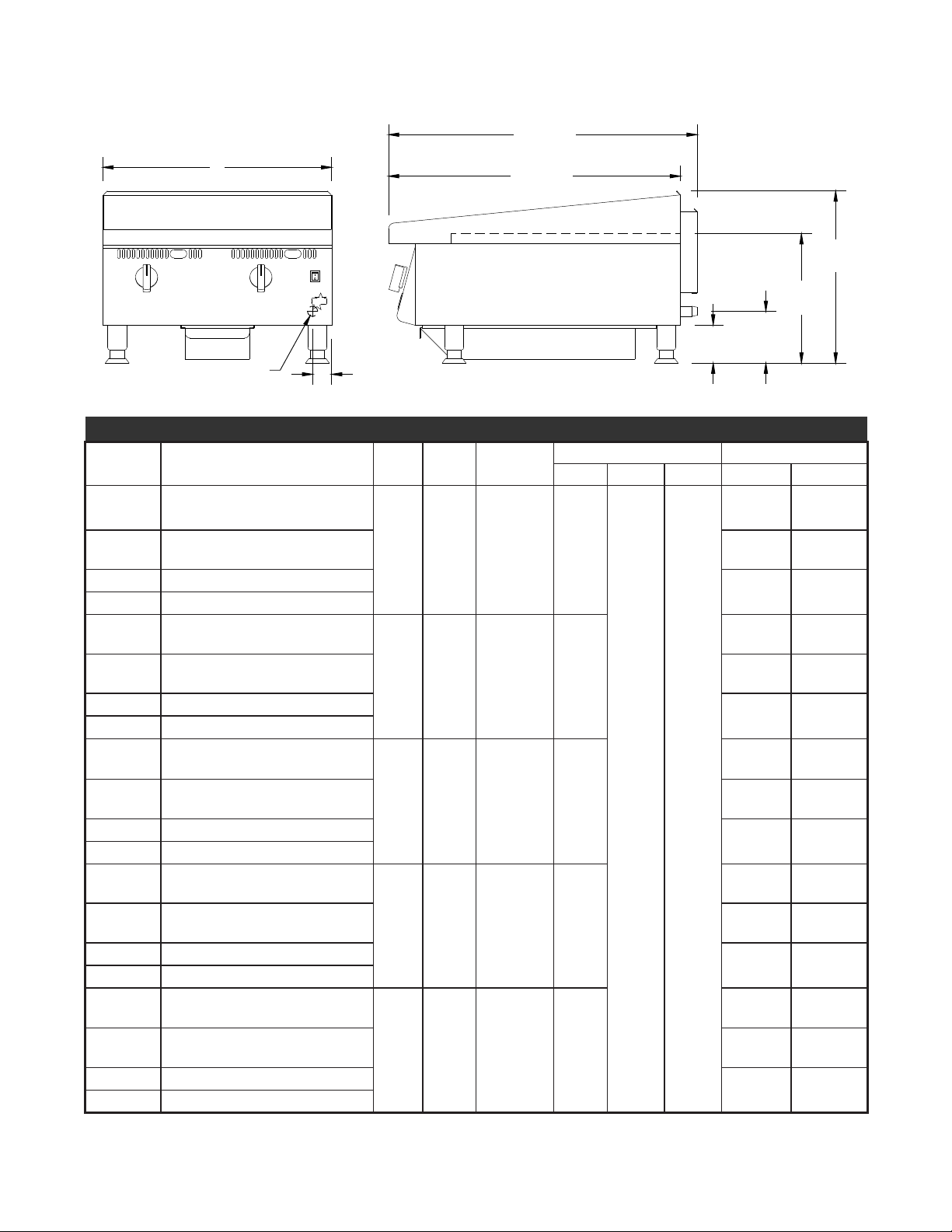
SPECIFICATIONS
IL2241
A
B
30 5/8”
(77.8CM)
18”
(45.8CM)
13 9/16”
(34.4CM)
7 7/16”
(13.8CM)
4”
(10.1CM)
32 3/8”
(82.3CM)
GAS INLET
Model Type Controls BTUH Griddle Area
824M Manual Valve
824T/TM Throttling Control
824TS Snap Action Control
824TSCHS Snap Action Control w/Crome Plate
836M Manual Valve
836T Throttling Control
836TS Snap Action Control
836TSCHS Snap Action Control w/Crome Plate
848M Manual Valve
848T Throttling Control
848TS Snap Action Control
848TSCHS Snap Action Control w/Crome Plate
860M Manual Valve
860T Throttling Control
860TS Snap Action Control
860TSCHS Snap Action Control w/Crome Plate
872M Manual Valve
872T
Throttling Control
872TS Snap Action Control
872TSCHS Snap Action Control w/Crome Plate
2 60,000
3 90,000
4 120,000
5 150,000
6 180,000
573 sq in
(3697sq. cm)
860 sq. in.
(5545 sq. cm)
1146 sq. in
(7397 sq. cm)
1433 sq in
(9242 sq cm)
1719 sq in
(11091 sq cm)
Dimensions Approx Weight
Width Depth Height Installed Shipping
214lbs
24"
(61cm)
(97kg)
220lbs
(99.7kg)
(110.6kg)
(111.5kg)
222lbs
(100.6kg)
(113.3kg)
321lbs
36"
(91.4cm)
(145.4kg)
330lbs
(149.5kg)
(165.8kg)
(167.2kg)
333lbs
(150.9kg)
(169.9kg)
428lbs
48"
(122cm)
32 3/8"
(82.2cm)
18"
(45.7cm)
(193.3kg)
440lbs
(199.4kg)
(221.1kg)
(222.9kg)
444lbs
(201.2kg)
(226.6kg)
535lbs
60"
(152.4cm)
(242.4kg)
550lbs
(249.2kg)
(276.4kg)
(278.7kg)
555lbs
(251.5kg)
(283.2kg)
642lbs
72"
(182.9cm)
(290.9kg)
660lbs
(299kg)
666lbs
(301.8kg)
(331.7kg)
(334.4kg)
(339.8kg)
244lbs
246lbs
250lbs
366lbs
369lbs
375lbs
488lbs
492lbs
500lbs
610lbs
615lbs
625lbs
732lbs
738lbs
750lbs
33
Page 4

CAUTION
GENERAL INSTALLATION DATA
This equipment is designed and sold for commercial use only by personnel trained and experienced
in its operation and is not sold for consumer use in and around the home nor for use directly by the
general public in food service locations.
Before using your new equipment, read and understand all the instructions & labels associated with
the unit prior to putting it into operation. Make sure all people associated with its use understand the
units operation & safety before they use the unit.
Ultra-Max series griddles are equipped for use on either natural or propane gas. All units are shipped
for natural gas and can easily be converted to propane. See Propane Gas - Conversion.
-IMPORTANT-
Be sure to remove all paper protection and packing material from unit prior to
lighting. Remove the protective plastic from the griddle plate and thoroughly
clean the unit's exterior surfaces.
KEEP THE APPLIANCE AREA FREE AND CLEAR FROM COMBUSTIBLES! For
use on non-combustible countertops only. Combustible and non-combustible
material must be at least 48" (120cm) from the top of the appliance and at
least 6" (16cm) from the sides and back. Adequate clearance should also be
provided for proper operation and servicing.
The installation of the Appliance must conform to the NATIONAL FUEL GAS
CODE "ANSI Z223.1 - LATEST EDITION" AND ALL LOCAL GAS COMPANY
RULES AND REGULATIONS.
IN CANADA INSTALLATION SHALL BE IN ACCORDANCE WITH THE
CURRENT CAN/CGA-B149.1 NATURAL GAS INSTALLATION CODE OR
CAN/CGA-B149.2 PROPANE INSTALLATION CODE AND LOCAL CODES
WHERE APPLICABLE.
NOTICE
When this appliance is installed with casters, it must be installed with the casters supplied, a connector
complying with either ANSI Z21.69 or CAN/CGA-6.16 and a quick-disconnect device complying with
either ANSI Z21.41 or CAN1-6.9. It must also be installed with restraining means to guard against
transmission of strain to the connector.
For your protection, we recommend a qualied installing agency install this appliance.
They should be familiar with gas installations and your local gas requirements. In any
case, your gas company should be called to approve the nal installation.
This appliance, its pressure regulator and its individual shutoff valve must be disconnected from the
gas supply piping system during any pressure testing of that system at test pressures in excess of 1/2
PSIG. This appliance and its pressure regulator must be isolated from the gas supply piping system by
closing its individual manual shutoff valve during any pressure testing of the gas supply piping system
at test pressures equal to or less than 1/2 PSIG.
EXHAUST CANOPY
Griddles inherently create a good deal of heat and smoke and should be installed under an efcient
exhaust hood with ame proof lters. A vertical distance of not less than 48" shall be provided between
the top of the appliance and lters or any other combustible material. Exhaust installation must
conform to local codes.
CAUTION
AIR SUPPLY: Provisions for adequate air supply must be provided.
AIR INTAKES IN BOTTOM
Air for combustion enters from the bottom of the unit. Do not obstruct this area.
44
Page 5

CAUTION
LEVELING UNIT
This griddle is supplied with 4 feet or oor stand legs which must be screwed into the body. After
the griddle is in its nal position, adjust the legs to create 1/8 inch slant from back to front. This will
allow the grease to run into the grease gutter and provide the proper combustion air for the burners.
Adjusting the (4) feet which have an adjustment of 1-3/4" for accurate and perfect line-up with other
units.
DO NOT INSTALL WITHOUT ATTACHING FEET OR SUPPLIED STAND LEGS
AND SHELF - DO NOT REMOVE FEET.
Caster Kits: Casters can be used with oor
stand models or optional equipment stand.
For installation, carefully mark and cut off from
the bottom of each leg using a straight cutting
saw and de-burr the inside tube wall prior to
installing the caster. Cut leg should measure
19" tube length, not overall length. Casters
add about 6-1/4" of height to the unit. Be
sure to use approved strain relief means for
protecting gas line connection. If an appliance
is equipped with casters and is gas connected
with a quick connect coupling, all personnel
must be aware that there is a restraint on the
appliance and if disconnected for service or
cleaning it must be reconnected as originally
installed prior to use.
55
Page 6

GAS PIPING
PLUG
IL1199
Natural
Regulator
Propane / LP
Gas piping shall be of such size and so installed as to provide a supply of gas sufcient to meet the
full gas input of the appliance. If the appliance is to be connected to existing piping, it shall be checked
to determine if it has adequate capacity. Joint compound shall be used sparingly and only on the male
threads of the pipe joints. Such compounds shall be resistant to the action of L.P. gases. WARNING:
Any loose dirt or metal particles which are allowed to enter the gas lines on this appliance will damage
the valve and affect its operation. When installing this appliance, all pipe and ttings must be free from
all internal loose dirt.
GAS PRESSURE REGULATOR
A convertible pressure regulator is provided with each griddle. It should be connected to the inlet pipe
at the rear of the unit. The gas supply is then connected to it. The supply pressure to the regulator
is not to exceed 1/2 psig. All units are shipped for use with natural gas. M and T Series Models are
shipped set for 5" water column manifold pressure. TS and TSCHS Series Models are shipped set for
4" water column manifold pressure.
MANUAL SHUT OFF VALVE
A manual shut off valve should be installed upstream from the manifold and within six feet of the
griddle.
CONNECTING GAS SUPPLY LINE
The gas inlet of the griddle is sealed at the factory to prevent entry of dirt. Do not remove this seal until
the actual connection is made to the gas supply line.
PROPANE GAS - CONVERSION
This griddle is equipped with xed orice hoods and is shipped from the factory for use with natural
gas. To convert to propane gas install the orice hoods located behind the front panel as follows:
1. Remove the front panel by removing the
screws located on the front and bottom.
2. Remove the burner mounting screws in the
center of the combustion chamber access
covers.
3. Slide the burners back off the orifice
hoods.
4. Remove the natural gas orice hoods and
install the propane orice hoods.
5. Slide the burners back over the orice hoods
and reinstall the burner mounting screws.
6. Reinstall the front panel.
7. Set the pressure regulator to 10" (25.4cm)
water column by removing the slotted or hex
cap from the center of the regulator. Invert
the plug and reinstall. The letters "LP" will now be visible on the plug. Reinstall the cap. An 1/8"
pipe plug is located on the manifold for attaching a pressure gauge.
CAUTION
CHECKING FOR GAS LEAKS
Check entire piping system for leaks. Soap and water solution or other material acceptable for the
purpose, shall be used in locating gas leakage.
Matches, candle ame or other sources of ignition shall not be used for
locating gas leaks.
66
Page 7
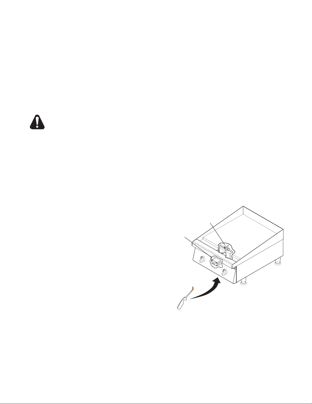
Pilot
Saftey Valve
IL1200
CAUTION
PILOT FLAME ADJUSTMENT
The griddles are equipped with standing pilots and should be lit immediately after the gas is
turned on.
MANUAL VALVE AND THROTTLING CONTROL MODELS
Adjust the ame as low as possible while still providing immediate burner ignition when
the control knob is turned to high.
SNAP ACTION THERMOSTAT AND CHROME SURFACE MODELS
Adjust the pilot so approximately 3/8" of the thermocouple tip is surrounded by
the pilot ame.
LIGHTING INSTRUCTIONS
When the griddle is rst lit, it will smoke until the preservative oils and impurities are burned off. The
griddles are equipped with standing pilots and should be lit immediately after the gas is turned on. The
Unit should be properly leveled prior to lighting.
DO NOT ATTEMPT TO LIGHT YOUR PILOT BURNER IF YOU EXPERIENCE A
STRONG GAS ODOR.
MANUAL VALVE AND THROTTLING CONTROL MODELS
1. Turn off the main valve to the unit and wait 5 minutes to clear gas.
2. Turn off all knobs and pilot valves.
3. Turn on main valve to unit and light all pilots.
4. Turn burner knobs to desired position.
5. To turn burners off, turn knobs to off.
SNAP ACTION THERMOSTAT AND CHROME SURFACE MODELS
1. Turn all knobs and power switch to
"OFF" and wait 5 minutes to clear gas.
Remove any grease trays.
2. Put lighter under the front of the griddle. FIG
1
3. Look through large hole in front panel.
4. Move lighter up to the pilot.
5. Put your other hand under the front of the
griddle and press the button on the safety
valve.
6. Once the pilot is lit, remove the lighter and
continue to press the button for at least 30
seconds.
7. Once pilot remains lit, continue to all other
pilot lights that need liting.
8. To turn burners off, turn off power switch.
FIG 1, Place Lighter under griddle
77
Page 8

CAUTION
BURNER AIR SHUTTER ADJUSTMENT
The burner air shutter has a locking screw on the bottom side of the venturi. Loosen this screw
to make any adjustment and tighten the screw to lock the air shutter in place after adjustment
is complete. Any adjustment must be made when the burner is at full input before the control
temperature setting has been satised.
1. Turn the control knob to the highest position and observe the burner ame.
2. Slowly decrease the air shutter opening until the ame is a soft blue with yellow tips, then increase
the opening until the yellow tips disappear and the ame is a hard blue.
3. Do not open the shutter to a point where the ame is unstable or lifting from the burner surface.
The ame must be steady and even across the entire burner.
The following was set at the factory and the adjustment should only be made
by an authorized installer and only if you are experiencing this specic
problem.
BYPASS ADJUSTMENT ON THROTTLING CONTROL MODELS ONLY
Throttling control models have a minimum ame setting that provides a steady uniform ame across
the burner when the control heat setting has been satised.
1. Set the control at the maximum setting and wait for the burner ame to throttle back.
2. Turn the dial to the 200 degree setting. A small steady ame should be visible on all the burner
ports. This ame should be approximately 1/8" high.
3. An adjustment screw is located either on the front or side of the control housing.
4. Turn clockwise to decrease the ame height; turn counterclockwise to increase the ame
CAUTION
CAUTION
ELECTRICAL CONNECTION FOR SNAP ACTION AND CHROME SURFACE
MODELS ONLY
Snap action and chrome surface griddles are equipped with a three-prong grounding plug. The unit
is designed for use on a 120 volt 15 amp 50/60 cycle AC single-phase circuit only. For protection
against electrical shock, the unit must be plugged directly into a properly grounded three-prong
receptacle. Do not cut or remove the grounding prong from this plug.
Do not connect to any other type of current or serious damage will occur.
OPERATING INSTRUCTIONS
SEASONING THE GRIDDLE HEATING SURFACE (NON-CHROME SURFACES)
Clean the griddle surface thoroughly. After the griddle has been thoroughly cleaned, it should be
seasoned to prevent food from sticking. Before using and after each thorough scouring, season the
griddle heating surface in the following manner:
1. Turn the temperature control dial to 350°F (174.0°C).
2. Using a clean cloth, not a spatula, spread a thin lm of cooking oil or shortening over the griddle
cooking surface. This lm should remain on the hot griddle surface 1/2 hour.
3. Remove excess shortening and wipe clean.
4. Apply another lm of cooking oil over the hot cooking area for another 1/2 hour, and again remove
excess shortening and wipe clean. The griddle surface should now be ready for use.
Even with careful seasoning food may, to some extent, stick to the griddle cooking
surface until griddle plate is "broken in."
COOKING
Set the dial knob to the setting desired. After a 30 minute (minimum) preheating period, the griddle
will automatically maintain the selected temperature.
88
Page 9

GRIDDLE CARE (NON-CHROME SURFACES)
It takes very little time and effort to keep the griddle attractive and performing at top efciency. If
grease is permitted to accumulate, it will form a gummy cake and then carbonize into a hard substance
which is extremely difcult to remove. To prevent this condition, the following suggestions for
cleanliness should be followed:
1. After each use, scrape the griddle with a scraper or exible spatula to remove excess grease and
food. A waste drawer is provided for the scrapings. If there is an accumulation of burned-on grease
and food, the griddle should be thoroughly scoured and reseasoned. Use pumice or griddle stone
while the griddle is warm. Do not use steel wool because of the danger of steel slivers getting into
the food.
2. Use a clean cloth and good non-abrasive cleaner to clean the stainless steel body of the griddle.
Wipe the control panel front with a soft cloth.
3. At least once a day, remove the waste drawer and wash in the same way as an ordinary cooking
utensil. The drawer is removed by pulling forward and out.
GRIDDLE CARE (CHROME SURFACES)
(Chrome surface griddles are marked with "CHS" at the end of the model number designation on the
nameplate.) It takes very little time and effort to keep this Industrial Chrome griddle surface sparkling
clean and performing at top efciency. DO NOT allow grease to accumulate as it will carbonize and
become difcult to remove. To prevent this condition, the following cleaning suggestions should be
followed:
1. Remove excess oil and food regularly with a 4" (100mm) wide razor sharp type scraper and wipe
surface with a damp cloth if desired.
2. Following the scraping, for end of the day cleaning, a damp cloth and a non-silicated, non-abrasive,
non-chlorinated cleaner such as Bon-Ami may be used to wipe surface clean, followed by wiping
with clean wet cloth.
3. Follow steps 2 and 3 from Griddle Care (Non-Chrome Surfaces).
CAUTION
CAUTION
CAUTION
1. Never use pumice, griddle stones, or abrasives on the surface.
2. Never strike the griddle surface with a sharp instrument or spatula edge.
3. Never use steel wool.
4. Never use commercial liquid grill cleaner on the griddle surface.
5. Abusing the surface voids the warranty.
WASTE DRAWER
A waste drawer is located at the front and can be removed from the front for cleaning by pulling drawer
forward. This drawer should be checked and emptied when necessary or at least once per day.
EXERCISE EXTREME CARE IN HANDLING THE WASTE DRAWER CONTAINING
HOT GREASE.
OVERNIGHT SHUTDOWN
MANUAL VALVE AND THROTTLING CONTROL MODELS
Turn knobs to the off position to turn burners off.
SNAP ACTION AND CHROME SURFACE MODELS
Turn knobs to the lowest setting and turn power switch off.
99
Page 10

CHROME GRIDDLE SURFACE LIMITED WARRANTY EXCLUSIONS
Your chrome griddle has been designed to give you many years of cooking reliability and requires
minimum maintenance to keep the chrome surface in its original condition. All chrome griddle surfaces
are warranted for a period of 5 years against manufacturing defects to the original owner from the
date of installation. This limited warranty is void if it is determined by Star Manufacturing International
Incorporated or one of its authorized representatives that the chrome surface has been misused or
abused or subjected to the following situations:
1. Improperly installed.
2. By-pass adjustments not set properly on gas units allowing the appliance to overheat and discolor the
chrome surface. (See by-pass adjustment section.)
3. The misuse of any instrument or tool which scratches or makes indentations in the surface which could
cause the surface to peel, ake, or chip off.
4. The use of any chemical or abrasive cleaning solution, griddle brick, stone, screen or other cleaning
products which could damage and affect the performance of the chome surface.
5. The neglect of daily routine maintenance to the chrome surface.
1010
Page 11

Ces symboles sont utilisés pour souligner à l’utilisateur les
instructions d’utilisation ou d’entretien importantes contenues
dans le manuel qui accompagne l’appareil.
CONSERVEZ CE MANUEL POUR RÉFÉRENCE FUTURE
AVIS
L’utilisation de toute pièce autre que les pièces d’origine STAR dégage le fabricant de toute responsabilité.
Star se réserve le droit de changer les spécifi cations et la conception du produit
sans préavis. Ces changements ne donnent pas le droit à l’acheteur d’obtenir
les changements, améliorations, ajouts ou remplacements correspondants pour
l’équipement acheté préalablement.
Dû aux modifi cations périodiques de dessins, méthodes, procédures, règles
et régulations, les spécifi cations contenues dans ce manuel sont susceptibles
de changer sans préavis. Quoique STAR Manufacturing exerce la bonne foi de
fournir le renseignement correct, STAR n’est pas responsable pour les erreurs
ou les omissions dans le renseignement pourvu ou les conclusions tirées à la
suite de l’utilisation des spécifi cations. En utilisant le renseignement pourvu,
l’utilisateur assume tous les risques en relation avec telle utilisation.
ENTRETIEN ET RÉPARATIONS
Contactez votre détaillent local pour les réparations ou l’entretien requis. Assurez-vous d’avoir
le numéro de modèle, le numéro de série, le voltage et la date d’achat pour un service plus
rapide. Entrez l’information requise ci-dessous pour référence rapide.
SYMBOLE DE SÉCURITÉ
N° de modèle
N° de série
Voltage
Date d’achat
Agent de service autorisé
Voir la liste pourvue avec l’appareil
Ou
Pour une liste mise à jour voir :
1111
Page 12

DONNÉES GÉNÉRALES D’INSTALLATION
ATTENTION
Ce matériel est conçu et vendu pour l’usage commercial seulement par le personnel qualié et expérimenté en
son exécution et n’est pas vendu pour l’usage du consommateur dans et autour de la maison ni pour l’usage
directement par le grand public dans des emplacements de service de traiteur.
Des grils de série d’Ultra-Max sont équipés pour l’usage sur le gaz naturel ou de propane. Toutes les unités sont
expédiées pour le gaz naturel et peuvent facilement être converties en propane. Voir Le Propane Intoxiquer - La
Conversion.
-IMPORTANT-
Soyez sûr d’enlever tout le matériel de papier de protection et d’emballage à partir de l’unité avant l’éclairage.
Éliminez le plastique protecteur du plat de gauffreuse et nettoyez complètement les surfaces extérieures de
l’unité.
MAINTENEZ LA RÉGION D’CAppareils LIBRE ET CLAIRE DES COMBUSTIBLES! Pour l’usage sur les
countertops non-combustibles seulement. Le matériel combustible et non-combustible doit être au moins 48 “
(120cm) à partir du dessus de l’appareil et au moins 6 “ (16cm) des côtés et du dos. Le dégagement adéquat
devrait également être donné pour l’exécution appropriée et l’entretien.
L’installation de l’appareil doit se conformer au CODE NATIONAL DE GAZ COMBUSTIBLE "ANSI
Z223.1 - TOUTE DERNIÈRE ÉDITION" DES
RÉGLEMENTATIONS DE LA COMPAGNIE DE GAZ LOCALE.
AU CANADA, L’INSTALLATION DOIT ÊTRE CONFORME AU CODE COURANT D’INSTALLATION
AU GAZ NATUREL CAN/CGA-B149.1 OU AU CODE D’INSTALLATION AU PROPANE CAN/CGAB149.2 ET AUX CODES LOCAUX, LE CAS ÉCHÉANT.
ÉTATS-UNIS ET À TOUTES LES RÈGLES ET
NOTIFICATION
Quand cet appareil est installé avec des roulettes, il doit être installé avec les roulettes fournies, un connecteur
étant conforme à la norme ANSI Z21.69 ou au CAN/CGA-6.16 et à un dispositif rapide étant conforme à la
norme ANSI Z21.41 ou au CAN1-6.9. Il doit également être installé avec des moyens retenants de garder
contre la transmission de la contrainte au connecteur.
Pour votre propre protection, on vous recommande de faire installer cet appareil par une agence d’installation
qualiée. Ils doivent connaître les installations de gaz et vos exigences de gaz locales. En tout cas, il faut
appeler votre société du gaz pour l’approbation de l’installation nale.
Cet appareil, son régulateur de pression et ses vannes d’arrêt individuelles doivent être débranchés de la
tuyauterie d’alimentation du gaz lors des essais de pression de la tuyauterie en question à des pressions en
dessus de ½ PSIG. Cet appareil et son régulateur de pression doivent être isolés de la tuyauterie d’alimentation
du gaz en fermant sa vanne d’arrêt manuelle individuelle lors des essais de pression de la tuyauterie
d’alimentation de gaz à des pressions égales à ou de moins que ½ PSIG.
ÉPUISEZ LE BALDAQUIN
Les grils créent en soi beaucoup de la chaleur et de la fumée et devraient être installés sous un capot efcace
d’échappement avec des ltres de preuve de amme. Une distance verticale pas moins de de 48 “ sera
fournie entre le dessus de l’appareil et les ltres ou n’importe quel autre matériel combustible. L’installation
d’échappement doit se conformer aux codes locaux.
LA PROVISION DE L'AIR
Les vivres pour provision de l'air adéquate doivent être fournis.
ATTENTION
PRISES D’AIR EN BAS
L’air nécessaire à la combustion entre par le bas de l’appareil. Ne bas boucher cette section.
1212
Page 13
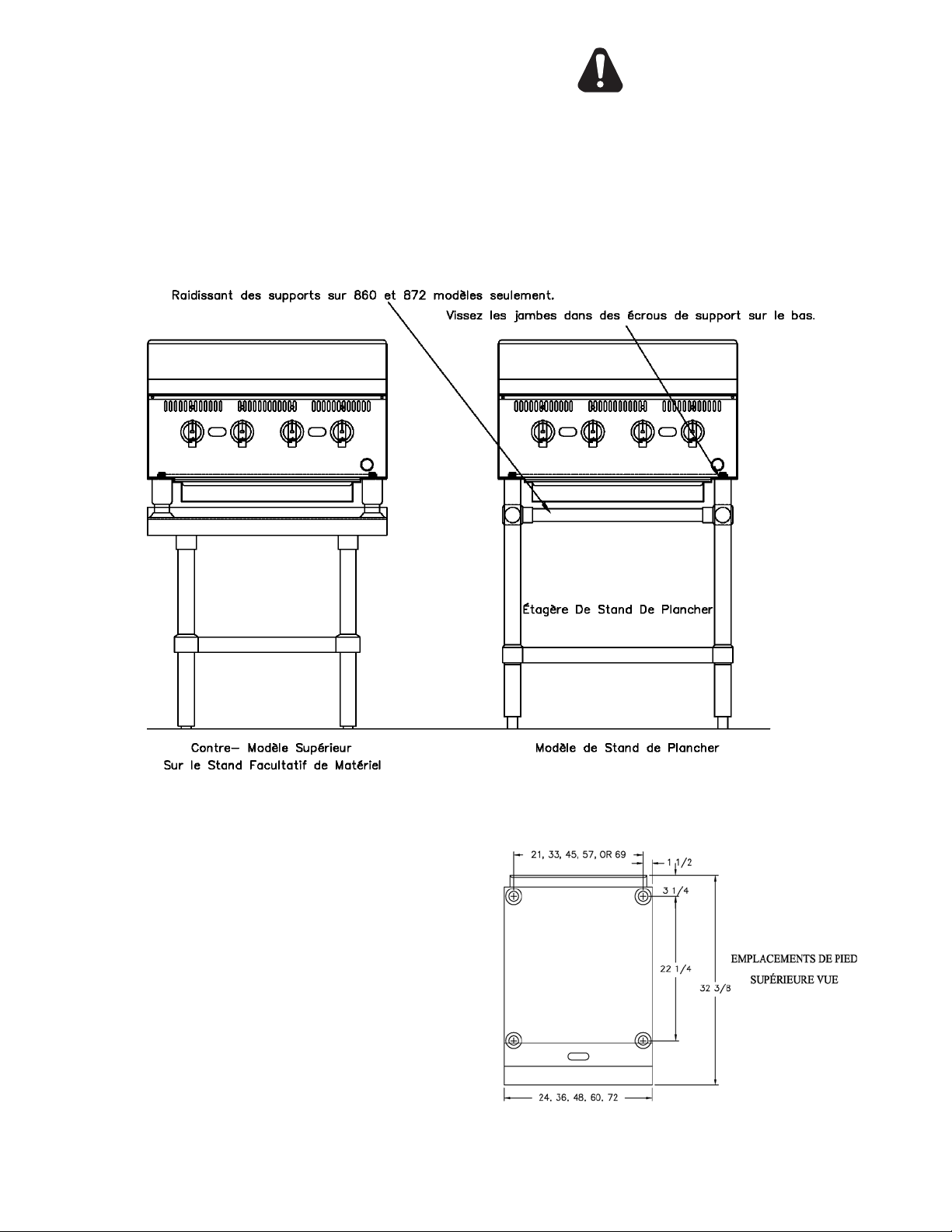
RASANT DE L'UNITÉ
Cette plaque en fonte est fournie 4 pieds ou jambes
d'éventaire d'étage qui doivent être vissées dans le
corps. Après que la plaque en fonte est dans sa position
nale, régler les jambes pour créer le point de vue de
pouce 1/8 d'à l'envers. Cela permettra à la graisse
de heurter la gouttière de graisse et fournir l'air de
combustion nécessaire aux brûleurs. Le réglage (le 4)
les pieds qui ont un ajustage de 1-3/4" pour l'équipe
exact et parfait avec d'autres unités.
ATTENTION
N’INSTALLEZ PAS SANS ATTACHER ES
PIEDS OU DES JAMBES ET L'ETAGERE
FOURNIES DE STAND.
Lots de roulettes: Des roulettes peuvent être utilisées
avec les modèles de stand de plancher ou le stand
de matériel facultatif. Pour d’installation la marque
soigneusement et découpé le de bas de chaque jambe
en utilisant une scie et un de-burr droits de découpage
le mur intérieur de tube avant d’installer la roulette.
La jambe de coupe devrait mesurer 19 “ longueur
de tube, longueur hors-tout. Les roulettes ajoutent
environ 6-1/4 “ de taille à l’unité. Soyez sûr d’utiliser
des moyens approuvés de passe-ls pour protéger la
connexion de ligne de gaz. Si un appareil est équipé
des roulettes et est gaz lié à un rapide relient le
couplage, tout le personnel doit se rendre compte qu’il
y ait une contrainte sur l’appareil et si débranché pour
le service ou le nettoyage qu’il doit être rebranché
comme initialement installé avant l’utilisation.
1313
Page 14

TUYAUTERIE À GAZ
La taille de la tuyauterie à gaz et la façon dont elle est installée doivent être telles qu’elle fournisse une
alimentation sufsante de gaz pour répondre aux exigences d’admission de pleine puissance dans l’appareil.
S’il faut raccorder l’appareil à la tuyauterie existante, il faut vérier cette dernière pour déterminer si elle a la
capacité nécessaire. Il ne faut utiliser le composé combiné que modérément et seulement sur les letages mâles
des raccords à tuyaux. Ces composés doivent résister à l’action des gaz propanes. AVERTISSEMENT : Toute
impureté libre ou particule métallique qui entre dans les canalisations de gaz de cet appareil endommagera la
vanne et en affectera le fonctionnement. Lors de l’installation de cet appareil, tous les tuyaux et raccords doivent
être exempts de toute impureté interne libre.
RÉGULATEUR DE PRESSION DU GAZ
Un régulateur de pression convertible est équipé de chaque gauffreuse. Il devrait être relié dans le tuyau
d’admission à l’arrière de l’unité. L’offre de gaz est alors reliée à elle. La pression d’approvisionnement au
régulateur ne doit pas excéder 1/2 psig. Toutes les unités sont expédiées pour l’usage avec le gaz naturel. Les
modèles de M et de séries de T sont positionnement expédié pour 5 “ pression de tubulure de colonne de l’eau.
Les modèles de série de SOLIDES TOTAUX et de TSCHS sont positionnement expédié pour 4 “ pression de
tubulure de colonne de l’eau.
VANNE D’ARRÊT MANUELLE
Une valve coupée manuelle devrait être installée en amont de la tubulure et à moins de six pieds du gril.
RACCORD DE LA CANALISATION DE GAZ
La prise de gaz du gril est scellée à l’usine pour empêcher l’entrée de la saleté. Ne retirez pas ce joint jusqu’à ce
que le rapport réel soit établi à la canalisation d’alimentation de gaz.
GAZ PROPANE - CONVERSION
Cette gauffreuse est équipée des capots xes d’orice et est expédiée de l’usine pour l’usage avec le gaz naturel.
Pour convertir en gaz de propane installez les capots de l’orice #52 situés derrière le panneau avant comme
suit:
1. Retirez le panneau avant en retirant les vis plac sur l’avant et le bas.
2. Retirez les vis de support de brûleur au centre de l’accès de chambre de combustion couvre.
3. Glissez les brûleurs dégagent les capots d’orice.
4. Retirez les capots d’orice de gaz naturel et installez les capots d’orice de propane.
5. Glissez les brûleurs en arrière au-dessus des capots d’orice et réinstallez les vis de support de brûleur.
6. Réinstallez le panneau avant.
7. Placez le régulateur de pression à 10 “ colonne de l’eau (de 25.4cm) en retirant le chapeau rainé ou d’hexa
du centre du régulateur. Inversez la prise et la réinstallez. Les lettres “ LP “ seront maintenant visibles sur la
prise. Réinstallez le chapeau. Un 1/8 “ prise de pipe est situé sur la tubulure pour attacher un indicateur de
pression.
LA VÉRIFICATION LE GAZ FUIT
Vérier l’étanchéité de toute la tuyauterie. Pour vérier l’étanchéité, il faut utiliser une solution de savon et d’eau
ou une autre matière acceptable pour ce but.
ATTENTION
Ne pas utiliser d’allumettes, la amme d’une chandelle ou d’autres sources d’allumage.
1414
Page 15

ALLUMER DES INSTRUCTIONS
Quand la gauffreuse est d’abord allumée, il fumera jusqu’à ce que les huiles et les impuretés de préservatif soient
consommation. Les gauffreuses sont équipées des pilotes debout et devraient être allumées juste après que le
gaz est allumé.
LA COMMANDE MANUELLE DE VALVE ET D’CÉtranglement MODÈLE
1. Arrêtez la valve principale à l’unité et attendez 5 minutes au gaz clair.
2. Arrêtez toutes les molettes et soupapes de commande.
3. Ouvrez la valve principale à l’unité et allumez tous les pilotes.
4. Tournez les molettes de brûleur à la position désirée.
5. Pour arrêter des brûleurs, tournez les molettes à hors fonction.
MODÈLES EXTÉRIEURS INSTANTANÉS DE THERMOSTAT ET DE CHROME D’CAction
1. Arrêtez la valve principale à l’unité et attendez 5 minutes au gaz clair.
2. Arrêtez le commutateur de puissance et tournez les thermostats à la plus basse conguration.
3. Ouvrez la valve principale.
4. Enfoncez et tenez le bouton pilote de remise de sûreté. Allumez le pilote. Tenez le bouton de remise pendant
60 secondes ou jusqu’ aux séjours pilotes s’est allumé. Répétition pour tous les pilotes.
5. Mettez en marche le commutateur de puissance et placez les thermostats à la position désirée.
6. Pour arrêter des brûleurs, arrêtez le commutateur de puissance.
RÉGLAGE PILOTE DE FLAMME
Les grils sont équipés des pilotes debout et devraient être allumés juste après que le gaz est allumé.
MODÈLES MANUELS DE COMMANDE DE VALVE ET D’CÉtranglement
Ajustez la amme aussi basse que possible tout en fournissant toujours l’allumage immédiat de brûleur quand le
bouton de commande est tourné à la haute.
MODÈLES EXTÉRIEURS INSTANTANÉS DE THERMOSTAT ET DE CHROME D’CAction Ajustez le pilote
tellement approximativement 3/8 “ de l’extrémité de thermocouple est entouré par la amme pilote.
RÉGLAGE D’CObturateur D’CAir DE BRÛLEUR
L’obturateur d’air de brûleur a une vis de blocage du côté inférieur du venturi. Desserrez cette vis pour faire
tout réglage et pour serrer la vis pour verrouiller l’obturateur d’air en place après que le réglage soit complet.
Tout réglage doit être fait quand le brûleur est à la pleine entrée avant que la conguration de la température de
commande ait été satisfaite.
1. Tournez le bouton de commande à la position la plus élevée et observez la amme de brûleur.
2. Diminuez lentement l’ouverture d’obturateur d’air jusqu’à ce que la amme soit un bleu mou avec des extrémités
jaunes, puis augmentez l’ouverture jusqu’à ce que les extrémités jaunes disparaissent et la amme est un
bleu dur.
3. N’ouvrez pas l’obturateur à un point où la amme est instable ou se soulevante de la surface de brûleur. La
amme doit être régulière et même à travers le brûleur entier.
LE RÉGLAGE DE DÉVIATION SUR LA COMMANDE D’CÉtranglement MODÈLE SEULEMENT
Les modèles de commande d’étranglement ont une conguration minimum de amme qui fournit une amme
uniforme régulière à travers le brûleur quand la conguration de la chaleur de commande a été satisfaite.
1. Placez la commande à la conguration et à l’attente de maximum la amme de brûleur à la commande de
puissance en arrière.
2. Tournez le cadran à la conguration de 200 degrés. Une petite amme régulière devrait être visible sur tous
les ports de brûleur. Cette amme devrait être approximativement 1/8 “ de haut.
3. Une vis d’approche est plac de l’avant ou du côté du logement de commande.
4. Tournez dans le sens des aiguilles d’une montre pour diminuer la taille de amme; tournez dans le sens
contraire des aiguilles d’une montre pour augmenter la amme.
1515
Page 16

CONNEXION ÉLECTRIQUE POUR L’CAction INSTANTANÉE ET LES MODÈLES EXTÉRIEURS DE CHROME
SEULEMENT
Des grils extérieurs instantanés d’action et de chrome sont équipés d’une trois-fourche fondant la prise. L’unité
est conçue pour l’usage sur 120 un circuit monophasé à C.A. de cycle de l’ampère 50/60 de volt 15 seulement.
Pour la protection contre le choc électrique, l’unité doit être branchée directement à un réceptacle correctement
fondé de trois-fourche. Ne coupez pas ou ne retirez pas la fourche fondante de cette prise.
INSTRUCTIONS DE FONCTIONNEMENT
EN ASSAISONNANT LA SURFACE de CHAUFFAGE de GRIL (SURFACES de NON-CHROME)
Nettoyez la surface de gril complètement. Après que le gril ait été complètement nettoyé, il devrait être
assaisonné pour empêcher la nourriture de coller. Avant utilisation et après chaque récurage complet,
assaisonnez la surface de chauffage de gril de la façon suivante:
1. Tournez le cadran de commande de la température à 350°F (174.0°C).
2. En utilisant un tissu propre, pas une spatule, a répandu une couche mince d’huile de cuisine ou de graisse
au-dessus du gril faisant cuire la surface. Ce lm devrait rester la demi-heure chaude de surface de gril.
3. Retirez gros excessif et le chiffon propres.
4. Appliquez un autre lm d’huile de cuisine au-dessus de la zone chaude de cuisine pour une autre demi-heure,
et encore retirez gros excessif et essuyez. La surface de gril devrait maintenant être opérationnelle.
Même avec la nourriture soigneuse d’assaisonnement peut, dans une certaine mesure, bâton au gril la
cuisine de la surface jusqu’à ce que le plat de gril "soit cassé dedans." CUISINE
Placez la molette de cadran à la conguration désirée. Après une période de préchauffage de 30 minutes
(minimum), le gril mettra à jour automatiquement la température choisie.
SOIN de GRIL (SURFACES de NON-CHROME)
Il prend le temps et l’effort très petits de maintenir le gril attrayant et exécutant en haut l’efcacité. Si la graisse
est autorisée pour s’accumuler, elle pour un gâteau gommeux et carboniser alors dans une substance dure il
est extrêmement difcile retirer que. Pour empêcher cette condition, les suggestions suivantes pour la propreté
devraient être suivies:
1. Après que chaque utilisation, éraent le gril avec un racleur ou une spatule exible pour enlever la graisse et
la nourriture excessives. Un tiroir de rebut est donné pour les raclures. S’ il y a une accumulation brûler-sur de
graisse et de nourriture, le gril devrait être complètement récuré et reseasoned. Utilisez la pierre de renovation
ou de gril tandis que le gril est chaud. N’utilisez pas les laines en acier en raison du danger des rubans en
acier entrant dans la nourriture.
2. Employez un tissu propre et un bon décapant non-abrasif pour nettoyer le corps d’acier inoxydable du gril.
Essuyez l’avant de pupitre de commande avec un tissu mou.
3. Du moins une fois par jour, retirent le tiroir de rebut et lavent de la même manière qu’une batterie de cuisine
ordinaire. Le tiroir est retiré en tirant en avant, vers le haut de et dehors.
1616
Page 17

SOIN de GRIL (SURFACES de CHROME)
(Des grils extérieurs de chrome sont identiés par “CHS“ à la n de la désignation de numéro de type sur la
plaque signalétique.) Elle prend le temps très petit et l’effort de maintenir ce scintillement extérieur de gril industriel
de chrome propre et exécuter en haut l’efcacité. Ne laissez pas la graisse s’accumuler car il carbonisera et
deviendra difcile de retirer. Pour empêcher cette condition, les suggestions suivantes de nettoyage devraient être
suivies:
1. Enlevez l’excédent d’huile et la nourriture régulièrement avec des 4 “ (100mm) racleur pointu de type de
rasoir large et essuyez la surface avec un tissu humide si désiré.
2. Après l’éraure, pour la n du nettoyage de jour, un tissu et un a humides non-silicated, décapant non abrasif
et non-chloré tel que la fève que l’ami peut être utilisé pour essuyer propre extérieur, suivi de l’essuyage avec
le tissu humide propre.
3. Suivez les étapes 2 et 3 du soin de gril (non surfaces de chrome).
ATTENTION
1. N’utilisez jamais la renovation, les pierres de gril, ou les abrasifs sur la surface.
2. Ne frappez jamais la surface de gril avec un instrument ou un bord pointu de spatule.
3. N’utilisez jamais les laines en acier.
4. N’utilisez jamais le décapant liquide commercial de gril sur la surface de gril.
5. Maltraiter la surface vide la garantie.
DE REBUT TIROIR
Un tiroir de rebut est situé à l’avant et peut être retiré de l’avant pour nettoyer en tirant le tiroir en avant. Ce tiroir
devrait être contrôlé et vidé si nécessaire ou au moins une fois par jour.
ATTENTION
PRENEZ LE SOIN EXTRÊME EN MANIPULANT LE TIROIR DE REBUT CONTENANT LA
GRAISSE CHAUDE.
ARRÊT DURANT LA NUIT MODÈLES
MANUELS DE COMMANDE DE VALVE ET D’CÉtranglement
Arrêtez les molettes à la position de repos aux brûleurs de tour.
CASSEZ L’CAction ET LES MODÈLES EXTÉRIEURS DE CHROME
Tournez les molettes à la plus basse conguration et arrêtez le commutateur de puissance.
EXCLUSIONS LIMITÉES DE GARANTIE DE SURFACE DE GRIL DE CHROME
Votre gril de chrome a été conçu pour vous donner beaucoup d’années de faire cuire la abilité et exige de
l’entretien minimum de maintenir la surface de chrome dans son état initial. Toutes les surfaces de gril de chrome
sont justiées pendant une période de 5 ans contre des défauts de fabrication au propriétaire initial de la date de
l’installation. Cette garantie limitée est vide si elle est déterminée par Star Manufacturing International Incorporated
ou un de ses représentants autorisés que la surface de chrome a été abusée ou maltraitée ou soumise aux
situations suivantes:
1. Incorrectement installé.
2. Sautez les réglages non réglés correctement sur des unités de gaz en permettant à l’appareil de surchauffer
et décolorer la surface de chrome. (Voir la section de réglage de déviation.)
3. L’abus de tout instrument ou outil qui rayent ou font des impressions dans la surface qui pourrait causer la
surface à la peau, s’écailler, ou ébrécher hors fonction.
4. L’utilisation de tout produit chimique ou solution abrasive de nettoyage, brique de gauffreuse, pierre, écran ou
d’autres produits de nettoyage qui pourraient endommager et affectent l’exécution de la surface de chome.
5. La négligence de l’entretien courant quotidien sur la surface de chrome.
1717
Page 18

2M-4497-2 6/1312
The foregoing warranty is in lieu of any and all other warranties expressed or implied and constitutes the entire warranty.
FOR ASSISTANCE
Should you need any assistance regarding the Operation or Maintenance of any Star equipment; write, phone, fax or email our Service Department.
In all correspondence mention the Model number and the Serial number of your unit, and the voltage or type of gas you are using.
ALL:
* Pop-Up Toasters
* Butter Dispensers
* Pretzel Merchandisers
(Model 16PD-A Only)
* Pastry Display Cabinets
* Nacho Chip Merchandisers
* Accessories of any kind
* Sneeze Guards
* Pizza Ovens
(Model PO12 Only)
* Heat Lamps
* Pumps-Manual
Visit our Website at: www.star-mfg.com Email: [email protected]
THOROUGHLY INSPECT YOUR UNIT ON ARRIVAL
This unit has been tested for proper operation before leaving our plant to insure delivery of your unit in perfect condition. However, there are instances in which
the unit may be damaged in transit. In the event you discover any type of damage to your product upon receipt, you must immediately contact the transportation
company who delivered the item to you and initiate your claim with same. If this procedure is not followed, it may affect the warranty status of the unit.
LIMITED EQUIPMENT WARRANTY
All workmanship and material in Star products have a one (1) year limited warranty on parts & labor in the United States and Canada. Such warranty is limited
to the original purchaser only and shall be effective from the date the equipment is placed in service. Star's obligation under this warranty is limited to the repair
of defects without charge, by the factory authorized service agency or one of its sub-agencies. Models that are considered portable (see below) should be taken
to the closest Star service agency, transportation prepaid.
> Star will not assume any responsibility for loss of revenue.
> On all shipments outside the United States and Canada, see International Warranty.
* The warranty period for the Ultra-Max, Hot Plates, Griddles, Charbroilers is (3) years parts & labor.
* The warranty period for the Star-Max, Charbroilers, Griddles, Hot Plates, Fryers & Finishing Oven is (2) years parts & labor.
* The warranty period for the JetStar six (6) ounce & Super JetStar eight (8) ounce series popcorn machines is two (2) years.
* The warranty period for the Chrome-Max Griddles is ve (5) years on the griddle surface. See detailed warranty provided with unit.
* The warranty period for Teon/Dura-Tec coatings is one year under normal use and reasonable care. This warranty does not apply if damage occurs to
Teon/Dura-Tec coatings from improper cleaning, maintenance, use of metallic utensils, or abrasive cleaners, abrasive pads, product identiers and
point-of-sale attachments, or any other non-food object tha comes in continuous contact with the roller coating. This warranty does not apply to the
“non-stick” properties of such materials.
> This warranty does not apply to "Special Products" but to regular catalog items only. Star's warranty on "Special Products" is six (6) months on parts
and ninety (90) days on labor.
> This warranty does not apply to any item that is disassembled or tampered with for any purpose other than repair by a Star Authorized Service Center or
the Service Center's sub-agency.
> This warranty does not apply if damage occurs from improper installation, misuse, wrong voltage, wrong gas or operated contrary to the Installation and
Operating instructions.
> This warranty is not valid on Conveyor Ovens unless a "start-up/check-out" has been performed by a Factory Authorized Technician.
PARTS WARRANTY
Parts that are sold to repair out of warranty equipment are warranted for ninety (90) days. The part only is warranted, the labor to replace the part is NOT warranted.
SERVICES NOT COVERED BY WARRANTY
PORTABLE EQUIPMENT
Star will not honor service bills that include travel time and mileage charges for servicing any products considered "Portable" including items listed below.
These products should be taken to the Service Agency for repair:
1. Travel time and mileage rendered beyond the 50 mile radius limit
2. Mileage and travel time on portable equipment (see below)
3. Labor to replace such items that can be replaced easily during a daily cleaning
routine, ie; removable kettles on fryers, knobs, grease drawers on griddles, etc.
4. Installation of equipment
5. Damages due to improper installation
6. Damages from abuse or misuse
7. Operated contrary to the Operating and Installation Instructions
8. Cleaning of equipment
9. Seasoning of griddle plates
10. Voltage conversions
11. Gas conversions
12. Pilot light adjustment
13. Miscellaneous adjustments
14. Thermostat calibration and by-pass adjustment
15. Resetting of circuit breakers or safety controls or reset buttons
16. Replacement of bulbs
17. Replacement of fuses
18. Repair of damage created during transit, delivery, &
installation OR created by acts of God
* The Model 510FD, 510FF Fryer.
* The Model 526TOA Toaster Oven.
* The Model J4R, 4 oz. Popcorn Machine.
* The Model 518CMA & 526CMA Cheese Melter.
* The Model 12MC & 15MC & 18MCP Hot Food Merchandisers.
* The Model 12NCPW & 15NCPW Nacho Chip/Popcorn Warmer.
* All Hot Dog Equipment except Roller Grills & Drawer Bun Warmers.
* All Nacho Cheese Warmers except Model 11WLA Series Nacho Cheese Warmer.
* All Condiment Dispensers except the Model HPD & SPD Series Dispenser.
* All Specialty Food Warmers except Model 130R, 11RW Series, and 11WSA Series.
* All QCS/RCS Series Toasters except Model QCS3 & RCS3 Series.
* All Fast Steamer Models except Direct Connect Series.
1818
Page 19

1919
Page 20
STAR MANUFACTURING INTERNATIONAL, INC.
SK1878 REV B 3-30-09
Model: 800 SERIES
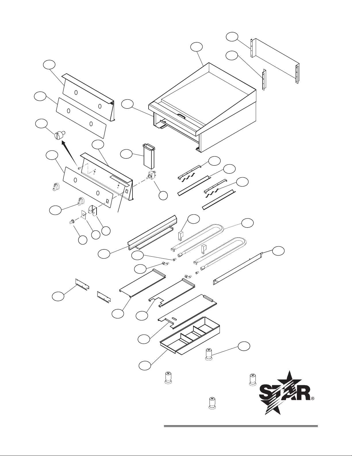
REFER TO THE PARTS LIST SPECIFIC
TO YOUR MODEL FOR MORE DETAIL INFORMATION.
23
19
22
19
20
21
3
1
4
5
6
9
18
7
8
16
15
13
12
11
10
2
14
17
24
NAMEPLATE
25
29
28
27
26
1414
Page 21

PARTS LIST August 27, 2012, Rev H
Ultra-Max Gas Griddle Models: 824M, 824T, 824TS, 824TM, 824TCHS, 824TSCHS
Fig. No Part No. Qty Description Application
1 G5-Z4812 1 FLUE 824M/T/TS/TSCHS
G5-824004
3
G5-824005 824T/TS
G5-824006 824TSCHS, 824TCHS
4 G5-Z4793 2 BULB CLAMP 824T/TS/TSCHS
5 G5-Z4794 2 BULB COVER 824T/TS/TSCHS
6 2P-Z4795 6 BULB SPRING 824T/TS/TSCHS
7 G5-Z4927 2 ORIFICE BRACKET 824M/T/TS/TSCHS
8 2F-Z4613 2 BURNER 824M/T/TS/TSCHS
9 G5-Z4800 1 SIDE BAFFLE RIGHT ALL 824/36/48/60/72
10 2A-Z4614 4 FOOT ALL 824/36/48/60/72
11 G5-824014 1 WASTE DRAWER ASSY ALL 824/836/848
12 G5-Z4897 1 DRAWER GUIDE ALL 824/836/848
13 G5-Z4799 1 PILOT BAFFLE 824TS/TSCHS
14 G5-Z4798 1 BURNER BAFFLE 824M/T
15 G5-Z4900 2 BURNER COVER 824M/T/TS/TSCHS
16 2A-9369 2 ORIFICE FITTING 824M/T/TS/TSCHS
2A-Z4930
17
2A-Z4931 ORIFICE PROPANE (SIZE 52) 824M/T/TS/TSCHS
2A-Z5542 ORIFICE NATURAL (SIZE 37) 824TS/TSCHS
18 G5-Z4801 1 SIDE BAFFLE LEFT ALL 824/36/48/60/72
2M-Z4862
19
2M-Z4863 824T, 824TCHS
2M-Z4864 OVERLAY 824TS 824TS/TSCHS
2R-Z4997 2 KNOB 824M/T, 824TCHS
20
2R-Z8891 2 KNOB, CONTROL U-MAX SNAP ACTION 824TS/TSCHS manuf. after 8/2005
PS-Z9312 2 KNOB SERVICE KIT 824TS/TSCHS manuf. before 8/2005
21 G5-824012 1 CHUTE ASSEMBLY ALL 824/836/848
G5-824008
22
G5-824026 FRONT PANEL ASSEMBLY (MOE’S) 824TM
23 G5-824025 1 FRONT PANEL ASSEMBLY 824TS/TSCHS
24 G5-824007 1 BODY ASSEMBLY 824M/T/TS/TSCHS
25 2C-Z8547 2 SCREW, 6-32 SHOULDER, KNOB STOP
2E-Z1858
26
PS-Z13373 ROCKER TO TOGGLE SWITCH KIT Optional Replacment to Toggle
Z1-70-07-0343
27
28
2M-12-07-0038
29 2I-05-07-0013 1 BOOT SWITCH 824TS, 824TSCHS
N/A 2J-Z4686 1 REGULATOR (5” NAT. AND 10” LP) ALL M/T, 824TCHS
N/A 2J-Z5541 1 REGULATOR (4” NAT AND 10” LP) ALL TS/TSCHS
N//A 2C-Z8547 AR BOLT, KNOB STOP
1 GRIDDLE PLATE ASSY COMPLETE
ORIFICE NATURAL (SIZE 41) 824M/T, 824TCHS
2
CONTROL GRAPHICS PANEL
1
FRONT PANEL ASSEMBLY 824M/T, 824TCHS
1
SWITCH-TOGGLE 2P 2T 824TS, 824TSCHS
1
1 SWITCH GUARD 824TS, 824TSCHS
1 LABEL ON & OFF 824TS, 824TSCHS
824M
824M
IMPORTANT: WHEN ORDERING, SPECIFY VOLTAGE OR TYPE GAS DESIRED PAGE
INCLUDE MODEL AND SERIAL NUMBER OF
Some items are included for illustrative purposes only and in certain instances may not be available.
Star International Holdings Inc. Company
1515
1
1
Page 22

PARTS LIST August 27, 2012, Rev H
Ultra-Max Gas Griddle Models: 836M, 836T, 836TS, 836TCHS, 836TSCHS
Fig. No Part No. Qty Description Application
1 G5-Z4813 1 FLUE 836M/T/TS/TSCHS
2 G5-Z4817 1 FLUE DIVIDER 836M/T/TS/TSCHS
G5-836004
3
G5-836005 836T/TS
G5-836006 836TSCHS, 836TCHS
4 G5-Z4793 3 BULB CLAMP 836T/TS/TSCHS
5 G5-Z4794 3 BULB COVER 836T/TS/TSCHS
6 2P-Z4795 9 BULB SPRING 836T/TS/TSCHS
7 G5-Z4927 3 ORIFICE BRACKET 836M/T/TS/TSCHS
8 2F-Z4613 3 BURNER 836M/T/TS/TSCHS
9 G5-Z4800 1 SIDE BAFFLE RIGHT ALL 824/36/48/60/72
10 2A-Z4614 4 FOOT ALL 824/36/48/60/72
11 G5-824014 1 WASTE DRAWER ASSY ALL 824/836/848
12 G5-Z4897 1 DRAWER GUIDE ALL 824/836/848
13 G5-Z4799 2 PILOT BAFFLE 836TS/TSCHS
14 G5-Z4798 2 BURNER BAFFLE 836M/T, 836TCHS
15 G5-Z4900 3 BURNER COVER 836M/T/TS/TSCHS
16 2A-9369 3 ORIFICE FITTING 836M/T/TS/TSCHS
2A-Z4930
17
18 G5-Z4801 1 SIDE BAFFLE LEFT ALL 824/36/48/60/72
19
20
21 G5-824012 1 CHUTE ASSEMBLY ALL 824/836/848
22 G5-836008 1 FRONT PANEL ASSEMBLY 836M/T, 836TCHS
23
24 G5-836007 1 BODY ASSEMBLY 836M/T/TS/TSCHS
25 2C-Z8547 3 SCREW, 6-32 SHOULDER, KNOB STOP
26
27 Z1-70-07-0343 1 SWITCH GUARD 836TS, 836TSCHS
28 2M-12-07-0038 1 LABEL ON & OFF 836TS, 836TSCHS
29 2I-05-07-0013 1 BOOT SWITCH 836TS, 836TSCHS
N/A 2J-Z4686 1 REGULATOR (5” NAT. AND 10” LP) ALL M/T, 836TCHS
N/A 2J-Z5541 1 REGULATOR (4” NAT. AND 10” LP) ALL TS/TSCHS
N/A 2C-Z8547 AR BOLT, KNOB STOP
N/A N2-30409
N/A N2-Z13276 836TSCHS-C
2A-Z4931 ORIFICE PROPANE (SIZE 52) 836M/T/TS/TSCHS
2A-Z5542 ORIFICE NATURAL (SIZE 37) 836TS/TSCHS
2M-Z4865
2M-Z4866 836T, 836TCHS
2M-Z11994 OVERLAY 836TS 836TS/TSCHS
2M-Z15618 OVERLAY 836TSCHS-C 836TSCHS-C
2R-Z4997
2R-Z8891 836TS/TSCHS, manuf. after 8/2006
PS-Z9312 KNOB SERVICE KIT 836TS/TSCHS, manuf. before 8/2006
G5-836025
G5-836027 FRONT PANEL ASSEMBLY 836 836TSCHS-C
2E-Z1858
PS-Z13373 ROCKER TO TOGGLE SWITCH KIT Optional Replacment to Toggle
1 GRIDDLE PLATE ASSY COMPLETE
ORIFICE NATURAL (SIZE 41) 836M/T, 836TCHS
3
CONTROL GRAPHICS PANEL
1
KNOB
3
FRONT PANEL ASSEMBLY 836TS 836TS/TSCHS
1
SWITCH-LIGHTED 836TS, 836TSCHS
1
1 LEAND IN CORD ASSY 120V
836M
836M
836M/T, 836TCHS
836TS, 836TSCHS
IMPORTANT: WHEN ORDERING, SPECIFY VOLTAGE OR TYPE GAS DESIRED PAGE
INCLUDE MODEL AND SERIAL NUMBER OF
Some items are included for illustrative purposes only and in certain instances may not be available.
Star International Holdings Inc. Company
1616
1
1
Page 23
PARTS LIST August 27, 2012, Rev H
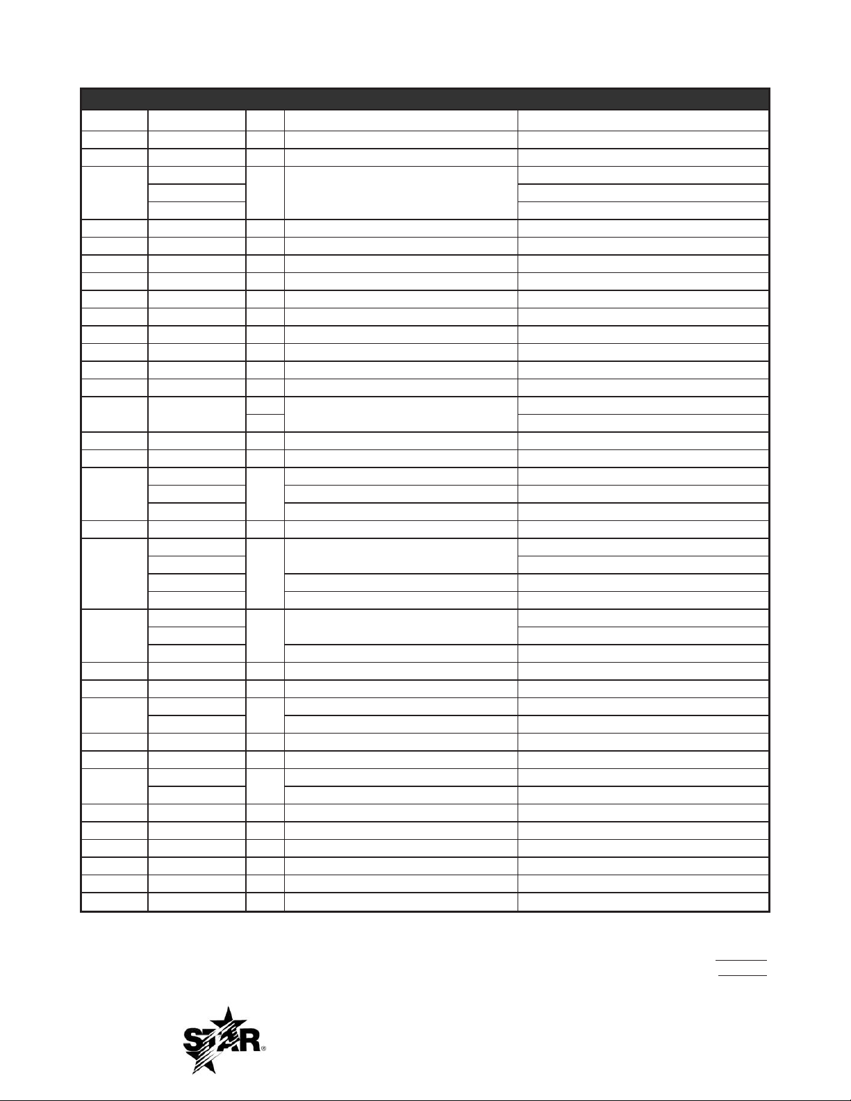
Ultra-Max Gas Griddle Models: 848M, 848T, 848TS, 848TCHS, 848TSCHS
Fig. No Part No. Qty Description Application
1 G5-Z4814 1 FLUE 848M/T/TS/TSCHS
2 G5-Z4817 1 FLUE DIVIDER 848M/T/TS/TSCHS
G5-848004
3
4 G5-Z4793 4 BULB CLAMP 848T/TS/TSCHS
5 G5-Z4794 4 BULB COVER 848T/TS/TSCHS
6 2P-Z4795 12 BULB SPRING 848T/TS/TSCHS
7 G5-Z4927 4 ORIFICE BRACKET 848M/T/TS/TSCHS
8 2F-Z4613 4 BURNER 848M/T/TS/TSCHS
9 G5-Z4800 1 SIDE BAFFLE RIGHT ALL 824/36/48/60/72
10 2A-Z4614 4 FOOT ALL 824/36/48/60/72
11 G5-824014 1 WASTE DRAWER ASSY ALL 824/836/848
12 G5-Z4897 1 DRAWER GUIDE ALL 824/836/848
13 G5-Z4799 2 PILOT BAFFLE 848TS/TSCHS
14 G5-Z4798
15 G5-Z4900 4 BURNER COVER 848M/T/TS/TSCHS
16 2A-9369 4 ORIFICE FITTING 848M/T/TS/TSCHS
17
18 G5-Z4801 1 SIDE BAFFLE LEFT ALL 824/36/48/60/72
19
20
21 G5-824012 1
22 G5-848008 1 FRONT PANEL ASSEMBLY 848M/T, 848TCHS
23
24 G5-848007 1 BODY ASSEMBLY 848M/T/TS/TSCHS
25 2C-Z8547 4 SCREW, 6-32 SHOULDER, KNOB STOP
26
27 Z1-70-07-0343 1 SWITCH GUARD 848TS, 848TSCHS
28 2M-12-07-0038 1 LABEL ON & OFF 848TS, 848TSCHS
29 2I-05-07-0013 1 BOOT SWITCH 848TS, 848TSCHS
N/A 2J-Z4686 1 REGULATOR (5” NAT. AND 10” LP) ALL M/T, 848TCHS
N/A 2J-Z5541 1 REGULATOR (4” NAT. AND 10” LP) ALL TS/TSCHS
N//A 2C-Z8547 AR BOLT, KNOB STOP
G5-848005 848T/TS
G5-848006 848TSCHS, 848TCHS
2A-Z4930
2A-Z4931 ORIFICE PROPANE (SIZE 52) 848M/T/TS/TSCHS
2A-Z5542 ORIFICE NATURAL (SIZE 37) 848TS/TSCHS
2M-Z4868
2M-Z4869 848T, 848TCHS
2M-Z4870 OVERLAY 848TS 848TS/TSCHS
2M-Z13356 OVERLAY 848TSCHS-C 848TSCHS-C
2R-Z4997
2R-Z8891 848TS/TSCHS manu. after 8/2005
PS-Z9312 KNOB SERVICE KIT 848TS/TSCHS manu. before 8/2005
G5-848025
G5-848026 FRONT PANEL ASSY. 848TS 848TSCHS-C
2E-Z1858
PS-Z13373 ROCKER TO TOGGLE SWITCH KIT Optional Replacment to Toggle
1 GRIDDLE PLATE ASSY COMPLETE
3
BURNER BAFFLE
1 848TS/TSCHS
ORIFICE NATURAL (SIZE 41) 848M/T, 848TCHS
4
CONTROL GRAPHICS PANEL
1
KNOB
4
CHUTE ASSEMBLY ALL 824/836/848
FRONT PANEL ASSEMBLY 848TS/TSCHS
1
SWITCH-TOGGLE 2P 2T 848TS, 848TSCHS
1
848M
848M/T, 848TCHS
848M
848M/T, 848TCHS
IMPORTANT: WHEN ORDERING, SPECIFY VOLTAGE OR TYPE GAS DESIRED PAGE
INCLUDE MODEL AND SERIAL NUMBER OF
Some items are included for illustrative purposes only and in certain instances may not be available.
Star International Holdings Inc. Company
1717
1
1
Page 24

PARTS LIST August 27, 2012, Rev H
Ultra-Max Gas Griddle Models: 860M, 860T, 860TS, 860TCHS, 860TSCHS
Fig. No Part No. Qty Description Application
1 G5-Z4815 1 FLUE 860M/T/TS/TSCHS
2 G5-Z4817 1 FLUE DIVIDER 860M/T/TS/TSCHS
G5-860004
3
4 G5-Z4793 5 BULB CLAMP 860T/TS/TSCHS
5 G5-Z4794 5 BULB COVER 860T/TS/TSCHS
6 2P-Z4795 15 BULB SPRING 860T/TS/TSCHS
7 G5-Z4927 5 ORIFICE BRACKET 860M/T/TS/TSCHS
8 2F-Z4613 5 BURNER 860M/T/TS/TSCHS
9 G5-Z4800 1 SIDE BAFFLE RIGHT ALL 824/36/48/60/72
10 2A-Z4614 4 FOOT ALL 824/36/48/60/72
11 G5-824014 2 WASTE DRAWER ASSY ALL 860/872
12 G5-Z4897 2 DRAWER GUIDE ALL 860/872
13 G5-Z4799 3 PILOT BAFFLE 860TS/TSCHS
14 G5-Z4798
15 G5-Z4900 5 BURNER COVER 860M/T/TS/TSCHS
16 2A-9369 5 ORIFICE FITTING 860M/T/TS/TSCHS
17
18 G5-Z4801 1 SIDE BAFFLE LEFT ALL 824/36/48/60/72
19
20
21 G5-824012 2 CHUTE ASSEMBLY
22 G5-860008 1 FRONT PANEL ASSEMBLY 860M/T, 860TCHS
23
24 G5-860007 1 BODY ASSEMBLY 860M/T/TS/TSCHS
25 2C-Z8547 5 SCREW, 6-32 SHOULDER, KNOB STOP
26
27 Z1-70-07-0343 1 SWITCH GUARD 860TS, 860TSCHS
28 2M-12-07-0038 1 LABEL ON & OFF 860TS, 860TSCHS
29 2I-05-07-0013 1 BOOT SWITCH 860TS, 860TSCHS
N/A 2J-Z4686 1 REGULATOR (5” NAT. AND 10” LP) ALL M/T, 860TCHS
N/A 2J-Z5541 1 REGULATOR (4” NAT. AND 10” LP) ALL TS/TSCHS
N/A 2C-Z8547 AR BOLT, KNOB STOP
N/A 2A-Z13272 10 KNOB GUARD 860TSCHS-C
G5-860005 860T/TS
G5-860006 860TSCHS, 860TCHS
2A-Z4930
2A-Z4931 ORIFICE PROPANE (SIZE 52) 860M/T/TS/TSCHS
2A-Z5542 ORIFICE NATURAL (SIZE 37) 860TS/TSCHS
2M-Z4871
2M-Z4872 860T, 860TCHS
2M-Z11996
2M-Z13275 860TSCHS-C
2R-Z4997
2R-Z8891 860TS/TSCHS manu. after 8/2005
PS-Z9312 KNOB SERVICE KIT 860TS/TSCHS manu. before 8/2005
G5-860025
G5-860027 FRONT PANEL ASSY 860TS
2E-Z1858
PS-Z13373 ROCKER TO TOGGLE SWITCH KIT Optional Replacment to Toggle
1 GRIDDLE PLATE ASSY COMPLETE
4
BURNER BAFFLE
1 860TS/TSCHS
ORIFICE NATURAL (SIZE 41) 860M/T, 860TCHS
5
CONTROL GRAPHICS PANEL
1
OVERLAY 860TS
KNOB
5
FRONT PANEL ASSEMBLY 860TS/TSCHS
1
SWITCH-TOGGLE 2P 2T 860TS, 860TSCHS
1
860M
860M/T, 860TCHS
860M
860TS/TSCHS
860M/T
ALL 860/872
IMPORTANT: WHEN ORDERING, SPECIFY VOLTAGE OR TYPE GAS DESIRED PAGE
INCLUDE MODEL AND SERIAL NUMBER OF
Some items are included for illustrative purposes only and in certain instances may not be available.
Star International Holdings Inc. Company
1818
1
1
Page 25

PARTS LIST August 27, 2012, Rev H
Ultra-Max Gas Griddle Models: 872M, 872T, 872TS, 872TCHS, 872TSCHS
Fig. No Part No. Qty Description Application
1 G5-Z4816 1 FLUE 872M/T/TS/TSCHS
2 G5-Z4817 2 FLUE DIVIDER 872M/T/TS/TSCHS
G5-872004
3
G5-872005 872T/TS
G5-824006 872TSCHS, 872TCHS
4 G5-Z4793 6 BULB CLAMP 872T/TS/TSCHS
5 G5-Z4794 6 BULB COVER 872T/TS/TSCHS
6 2P-Z4795 18 BULB SPRING 872T/TS/TSCHS
7 G5-Z4927 6 ORIFICE BRACKET 872M/T/TS/TSCHS
8 2F-Z4613 6 BURNER 872M/T/TS/TSCHS
9 G5-Z4800 1 SIDE BAFFLE RIGHT ALL 824/36/48/60/72
10 2A-Z4614 4 FOOT ALL 824/36/48/60/72
11 G5-824014 2 WASTE DRAWER ASSY ALL 860/872
12 G5-Z4897 2 DRAWER GUIDE ALL 860/872
G5-Z4799 3 PILOT BAFFLE 872TS/TSCHS
13
15 G5-Z4900 6 BURNER COVER 872M/T/TS/TSCHS
16 2A-9369 6 ORIFICE FITTING 872M/T/TS/TSCHS
17
18 G5-Z4801 1 SIDE BAFFLE LEFT ALL 824/36/48/60/72
19
20
21 G5-824012 2 CHUTE ASSEMBLY ALL 860/872
22 G5-872008 1 FRONT PANEL ASSEMBLY 872M/T, 872TCHS
23 G5-872025 1 FRONT PANEL ASSEMBLY 872TS/TSCHS
24 G5-872007 1 BODY ASSEMBLY 872M/T/TS/TSCHS
25 2C-Z8547 2 SCREW, 6-32 SHOULDER, KNOB STOP
26
27 Z1-70-07-0343 1 SWITCH GUARD 872TS, 872TSCHS
28 2M-12-07-0038 1 LABEL ON & OFF 872TS, 872TSCHS
29 2I-05-07-0013 1 BOOT SWITCH 872TS, 872TSCHS
N/A 2J-Z4686 1 REGULATOR (5” NAT. AND 10” LP) ALL M/T, 872TCHS
N/A 2J-Z5541 1 REGULATOR (4” NAT. AND 10” LP) ALL TS/TSCHS
N//A 2C-Z8547 AR BOLT, KNOB STOP
G5-Z4798
2A-Z4930
2A-Z4931 ORIFICE PROPANE (SIZE 52) 872M/T/TS/TSCHS
2A-Z5542 ORIFICE NATURAL (SIZE 37) 872TS/TSCHS
2M-Z4874
2M-Z4875 872T, 872TCHS
2M-Z11997 872TS/TSCHS
2M-Z14472 OVERLAY 872TSCHS-C
2R-Z4997
2R-Z8891 872TS/TSCHS manuf. after 8/2005
PS-Z9312 KNOB SERVICE KIT 872TS/TSCHS manuf. before 8/2005
2E-Z1858 1 SWITCH-TOGGLE 2P 2T 872TS, 872TSCHS
PS-Z13373 ROCKER TO TOGGLE SWITCH KIT Optional Replacment to Toggle
1 GRIDDLE PLATE ASSY COMPLETE
5
BURNER BAFFLE
2 872TS/TSCHS
ORIFICE NATURAL (SIZE 41) 872M/T, 872TCHS
6
CONTROL GRAPHICS PANEL
1
KNOB
6
872M
872M/T, 872TCHS
872M
872M/T, 872TCHS
IMPORTANT: WHEN ORDERING, SPECIFY VOLTAGE OR TYPE GAS DESIRED PAGE
INCLUDE MODEL AND SERIAL NUMBER OF
Some items are included for illustrative purposes only and in certain instances may not be available.
Star International Holdings Inc. Company
1919
5
5
Page 26
STAR MANUFACTURING INTERNATIONAL, INC.
MODEL: 800M SERIES
SK1880 Rev. - 1-20-02
3
1
2
4
6
7
5
2020
Page 27

STAR MANUFACTURING INTERNATIONAL, INC.
MODEL: 800T SERIES
SK1879 Rev. - 1-20-02
3
1
2
6
4
5
7
2121
Page 28

PARTS LIST October 24, 2011, Rev H
800M and 800T Series
MODEL
Number
Key
Number
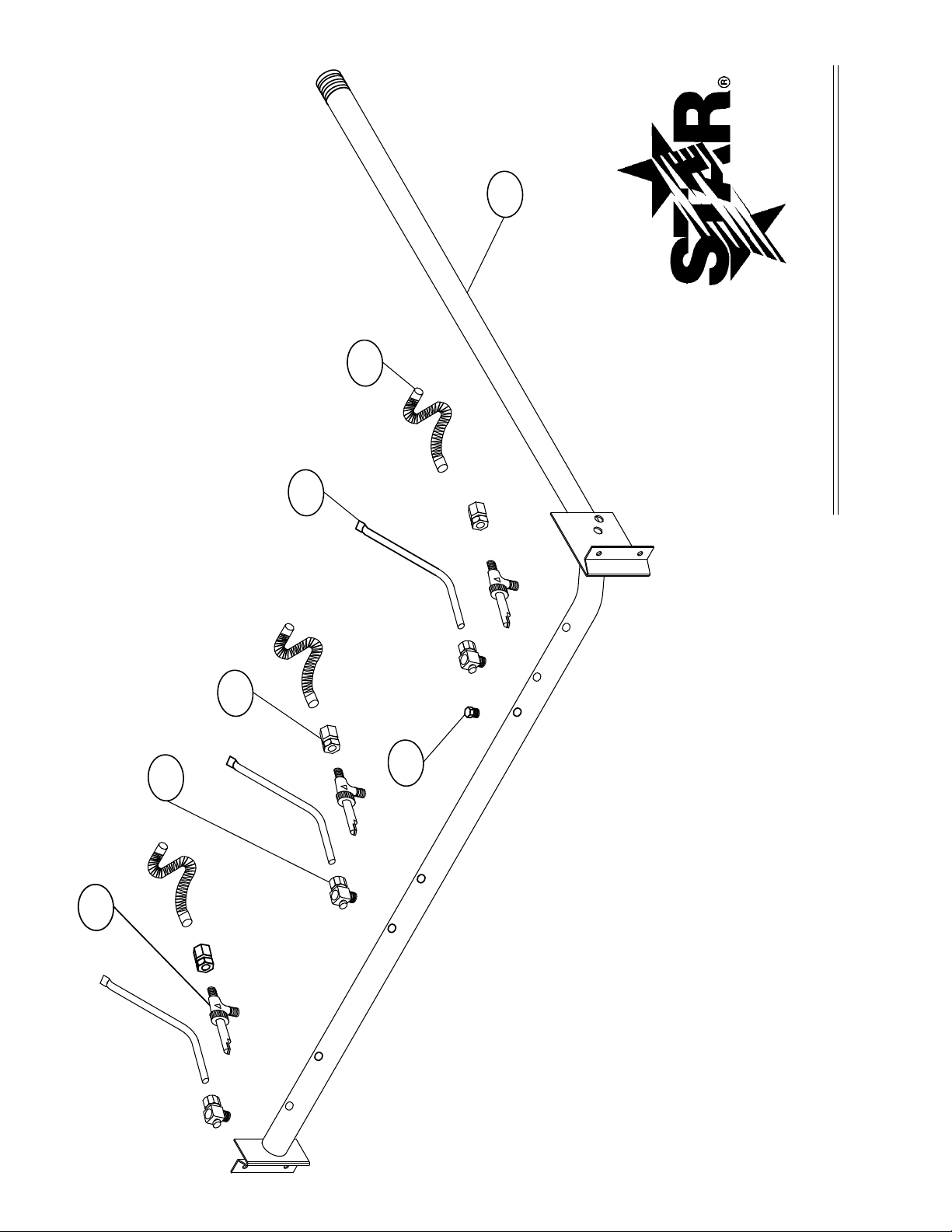
1 2K-Z4901 1 MANIFOLD 824M/T
2K-Z4902 1 MANIFOLD 836M/T
2K-Z4903 1 MANIFOLD 848M/T
2K-Z4904 1 MANIFOLD 860M/T
2K-Z4905 1 MANIFOLD 872M/T
2 2K-Z4921 2 BURNER FLEX TUBE 824M/T
3 BURNER FLEX TUBE 836M/T
4 BURNER FLEX TUBE 848M/T
5 BURNER FLEX TUBE 860M/T
6 BURNER FLEX TUBE 872M/T
3 2P-1453 1 PIPE PLUG ALL M/T
4 2V-Z4821 2 PILOT BURNER 824T
3 PILOT BURNER 836T
4 PILOT BURNER 848T
5 PILOT BURNER 860T
6 PILOT BURNER 872T
2V-Z4906 2 PILOT BURNER 824M
3 PILOT BURNER 836M
4 PILOT BURNER 848M
5 PILOT BURNER 860M
6 PILOT BURNER 872M
5 2V-6671 2 PILOT VALVE 824M/T
3 PILOT VALVE 836M/T
4 PILOT VALVE 848M/T
5 PILOT VALVE 860M/T
6 PILOT VALVE 872M/T
6 2T-Z4823 2 THROTTLING CONTROL 824T
3 THROTTLING CONTROL 836T
4 THROTTLING CONTROL 848T
5 THROTTLING CONTROL 860T
6 THROTTLING CONTROL 872T
2V-Y8832 2 MANUAL VALVE 824M
3 MANUAL VALVE 836M
4 MANUAL VALVE 848M
5 MANUAL VALVE 860M
6 MANUAL VALVE 872M
7 2A-Z0790 2 FITTING 3/8 CC X 3/8-27 824M
3 FITTING 3/8 CC X 3/8-27 836M
4 FITTING 3/8 CC X 3/8-27 848M
5 FITTING 3/8 CC X 3/8-27 860M
6 FITTING 3/8 CC X 3/8-27 872M
2K-Y7111 2 FITTING 3/8 CC X 1/4 MPT 824T
3 FITTING 3/8 CC X 1/4 MPT 836T
4 FITTING 3/8 CC X 1/4 MPT 848T
5 FITTING 3/8 CC X 1/4 MPT 860T
6 FITTING 3/8 CC X 1/4 MPT 872T
Part
Number
Per
Unit
Description
Model
IMPORTANT: WHEN ORDERING, SPECIFY VOLTAGE OR TYPE GAS DESIRED PAGE
INCLUDE MODEL AND SERIAL NUMBER OF
Some items are included for illustrative purposes only and in certain instances may not be available.
Star International Holdings Inc. Company
2222
1
1
Page 29

2323
Page 30
MODEL: 824TS AND 824TSCHS
STAR MANUFACTURING INTERNATIONAL, INC.
SK1885 Rev.- 01-20-02
10
2
1
6
4
5
7
8
9
21
20
19
16
15
13
12
11
3
31
17
14
22
L
L
L
L
1
1
24
25
26
27
28
29
30
23
0
2424
Page 31

PARTS LIST October 24, 2011, Rev H
824TS and 824TSCHS Series
MODEL
Number
Key
Number
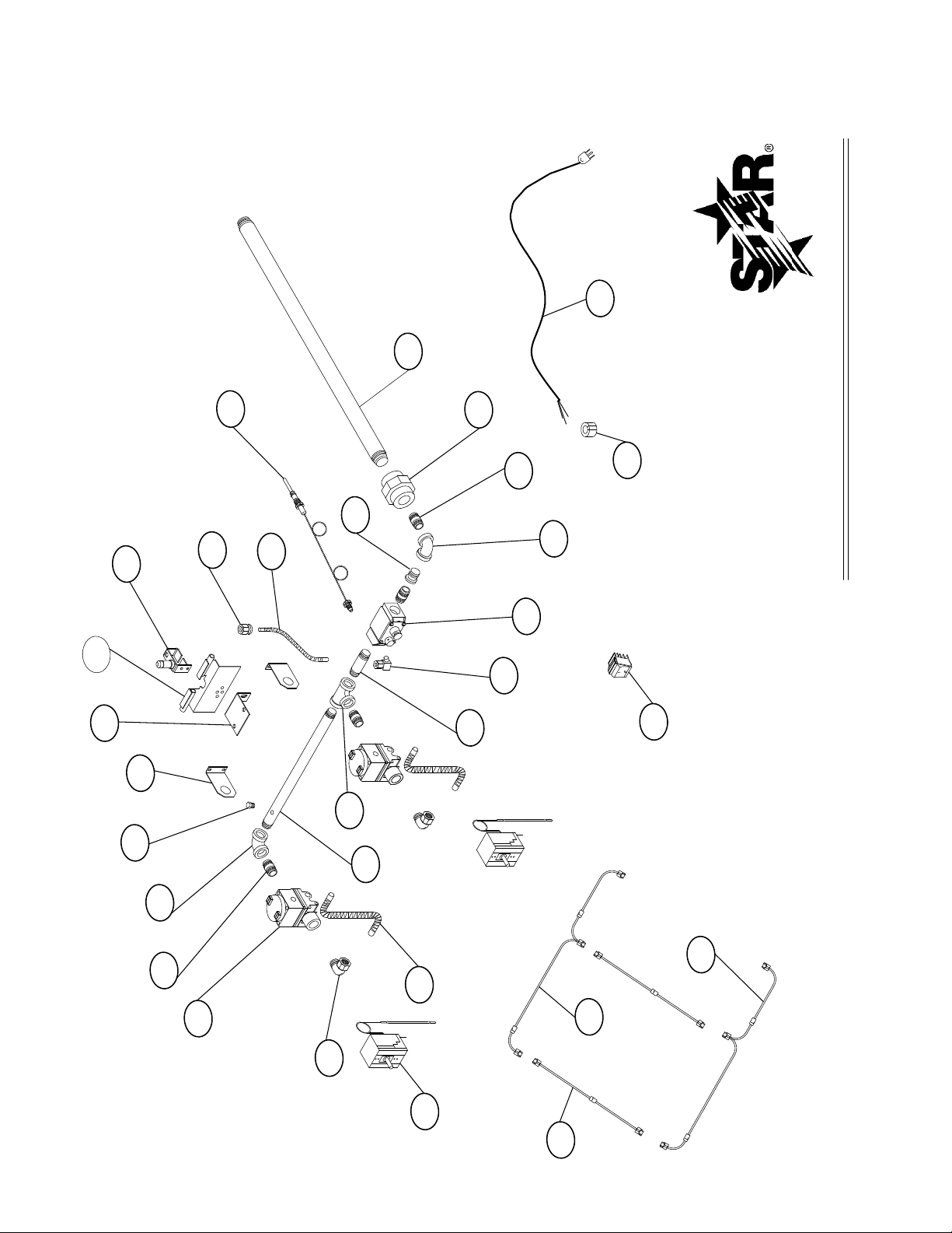
1 2K-Z4921 824TS/TSCHS 2 BURNER FLEX TUBE
2 2K-2675 824TS/TSCHS 2 FITTING 3/8 CC X 3/8 MPT
3 2P-1453 824TS/TSCHS 1 PIPE PLUG
4 2K-Y5550 824TS/TSCHS 3 NIPPLE 3/8 NPT X 1 1/2
5 2K-2665 824TS/TSCHS 1 ELBOW 3/8 NPT
6 2J-Z4610 824TS/TSCHS 2 SOLENOID VALVE
7 G5-Z4907 824TS/TSCHS 2 MOUNTING BRACKET
8 G5-824019 824TS/TSCHS 1 PILOT BRACKET ASSY
9 G5-824018 824TS/TSCHS 1 FLASH TUBE BRACKET ASSY
10 2J-Z4608 824TS/TSCHS 1 PILOT BURNER
11 2A-Y2017 824TS/TSCHS 1 PILOT ORIFICE
12 2K-Z4920 824TS/TSCHS 1 PILOT TUBE FLEX
13 2J-Z4609 824TS/TSCHS 1 THERMOCOUPLE
14 2K-Z4617 824TS/TSCHS 1 REDUCER BUSHING
15 2K-Z4616 824TS/TSCHS 1 INLET PIPE
16 2K-Z5033 824TS/TSCHS 1 UNION
17 2K-Z4618 824TS/TSCHS 1 NIPPLE 3/4 NPT X 2 1/4
19 2J-Z4607 824TS/TSCHS 1 SAFETY VALVE
20 2V-6671 824TS/TSCHS 1 PILOT VALVE
21 2K-Y4403 824TS/TSCHS 1 CLOSE NIPPLE 3/8 NPT
22 2K-9688 824TS/TSCHS 1 TEE 3/8 NPT
23 2K-Z4612 824TS/TSCHS 1 NIPPLE WITH PRESSURE TAP
24 2T-Z7440 824TS/TSCHS 2 THERMOSTAT manuf. after 8/2005
PS-Z9318 824TS/TSCHS 2 THERMOSTAT SERVICE KIT manuf. before 8/2005
25 G5-824015 824TS/TSCHS 2 WIRE ASSEMBLY #1
26 G5-824017 824TS/TSCHS 1 WIRE ASSEMBLY 824TS “C”
27 G5-824016 824TS/TSCHS 1 WIRE ASSEMBLY 824TS “L”
28 2E-Z1858 824TS/TSCHS 1 SWITCH
29 2K-Y2967 824TS/TSCHS 1 CORD BUSHING
30 N2-30409 824TS/TSCHS 1 CORD SET 6’ LONG
31 2K-Z4611 824TS/TSCHS 1 ELBOW 3/4 NPT
Part
Number
Model
Description
Per
Unit
IMPORTANT: WHEN ORDERING, SPECIFY VOLTAGE OR TYPE GAS DESIRED PAGE
INCLUDE MODEL AND SERIAL NUMBER OF
Some items are included for illustrative purposes only and in certain instances may not be available.
Star International Holdings Inc. Company
2525
1
1
Page 32
MODEL: 836TS AND 836TSCHS
STAR MANUFACTURING INTERNATIONAL, INC.
SK1884 Rev.- 01-20-02
13
10
8
9
15
5
4
6
2
1
20
19
21
14
18
17
16
11
12
3
23
22
7
L
1
25
26
L
1
27
L
L
24
28
29
30
L
L
1
0
2626
Page 33
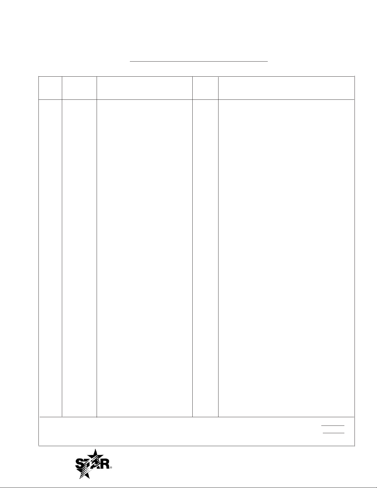
PARTS LIST October 24, 2011, Rev H
836TS and 836TSCHS Series
Key
Number
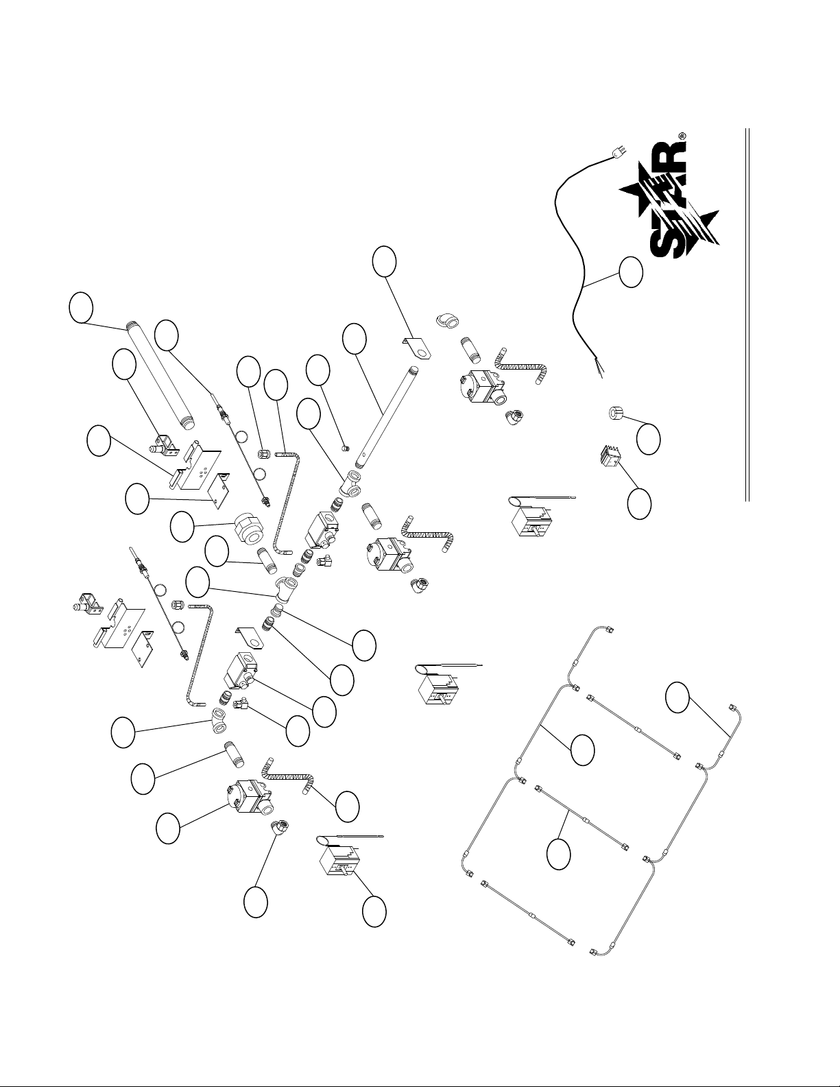
1 2K-Z4921 836TS/TSCHS 3 BURNER FLEX TUBE
2 2K-2675 836TS/TSCHS 3 FITTING 3/8 CC X 3/8 MPT
3 2P-1453 836TS/TSCHS 1 PIPE PLUG
4 2K-Y5550 836TS/TSCHS 3 NIPPLE 3/8 NPT X 1 1/2
5 2K-2665 836TS/TSCHS 2 ELBOW 3/8 NPT
6 2J-Z4610 836TS/TSCHS 3 SOLENOID VALVE
7 G5-Z4907 836TS/TSCHS 2 MOUNTING BRACKET
8 G5-824019 836TS/TSCHS 2 PILOT BRACKET ASSY
9 G5-824018 836TS/TSCHS 2 FLASH TUBE BRACKET ASSY
10 2J-Z4608 836TS/TSCHS 2 PILOT BURNER
11 2A-Y2017 836TS/TSCHS 2 PILOT ORIFICE
12 2K-Z4920 836TS/TSCHS 2 PILOT TUBE FLEX
13 2J-Z4609 836TS/TSCHS 2 THERMOCOUPLE
14 2K-Z4617 836TS/TSCHS 2 REDUCER BUSHING
15 2K-Z4616 836TS/TSCHS 1 INLET PIPE
16 2K-Z5033 836TS/TSCHS 1 UNION
17 2K-Z4618 836TS/TSCHS 1 NIPPLE 3/4 NPT X 2 1/4
18 2K-Z5034 836TS/TSCHS 1 3/4 NPT TEE
19 2J-Z4607 836TS/TSCHS 2 SAFETY VALVE
20 2V-6671 836TS/TSCHS 2 PILOT VALVE
21 2K-Y4403 836TS/TSCHS 4 CLOSE NIPPLE 3/8 NPT
22 2K-9688 836TS/TSCHS 1 TEE 3/8 NPT
23 2K-Z4612 836TS/TSCHS 1 NIPPLE WITH PRESSURE TAP
24 2T-Z7440 824TS/TSCHS 3 THERMOSTAT manuf. after 8/2005
PS-Z9318 824TS/TSCHS 3 THERMOSTAT SERVICE KIT manuf. before 8/2005
25 G5-824015 836TS/TSCHS 3 WIRE ASSEMBLY #1
26 G5-836017 836TS/TSCHS 1 WIRE ASSEMBLY 836TS “C”
27 G5-836016 836TS/TSCHS 1 WIRE ASSEMBLY 836TS “L”
28 2E-Z1858 836TS/TSCHS 1 SWITCH
29 2K-Y2967 836TS/TSCHS 1 CORD BUSHING
30 N2-30409 836TS/TSCHS 1 CORD SET 6’ LONG
Part
Number
MODEL
Model
Number
Description
Per
Unit
IMPORTANT: WHEN ORDERING, SPECIFY VOLTAGE OR TYPE GAS DESIRED PAGE
INCLUDE MODEL AND SERIAL NUMBER OF
Some items are included for illustrative purposes only and in certain instances may not be available.
Star International Holdings Inc. Company
2727
1
1
Page 34
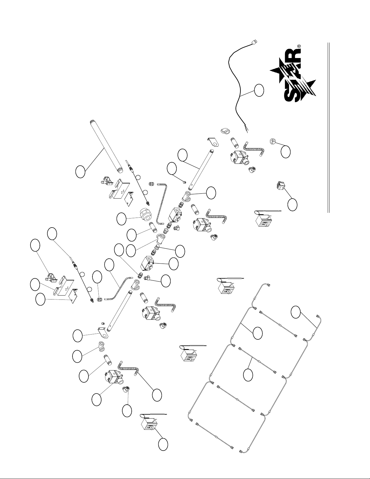
MODEL: 848TS AND 848TSCHS
STAR MANUFACTURING INTERNATIONAL, INC.
SK1883 Rev.- 01-20-02
13
10
9
8
1
2
6
4
5
7
11
12
21
20
19
14
17
15
16
23
3
18
22
24
27
L
1
L
L
1
1
25
26
L
L
L
28
29
0
30
L
1
L
2828
Page 35

PARTS LIST October 24, 2011, Rev H
848TS and 848TSCHS Series
MODEL
Number
Key
Number
1 2K-Z4921 848TS/TSCHS 4 BURNER FLEX TUBE
2 2K-2675 848TS/TSCHS 4 FITTING 3/8 CC X 3/8 MPT
3 2P-1453 848TS/TSCHS 2 PIPE PLUG
4 2K-Y5550 848TS/TSCHS 4 NIPPLE 3/8 NPT X 1 1/2
5 2K-2665 848TS/TSCHS 2 ELBOW 3/8 NPT
6 2J-Z4610 848TS/TSCHS 4 SOLENOID VALVE
7 G5-Z4907 848TS/TSCHS 2 MOUNTING BRACKET
8 G5-824019 848TS/TSCHS 2 PILOT BRACKET ASSY
9 G5-824018 848TS/TSCHS 2 FLASH TUBE BRACKET ASSY
10 2J-Z4608 848TS/TSCHS 2 PILOT BURNER
11 2A-Y2017 848TS/TSCHS 2 PILOT ORIFICE
12 2K-Z4920 848TS/TSCHS 2 PILOT TUBE FLEX
13 2J-Z4609 848TS/TSCHS 2 THERMOCOUPLE
14 2K-Z4617 848TS/TSCHS 2 REDUCER BUSHING
15 2K-Z4616 848TS/TSCHS 1 INLET PIPE
16 2K-Z5033 848TS/TSCHS 1 UNION
17 2K-Z4618 848TS/TSCHS 1 NIPPLE 3/4 NPT X 2 1/4
18 2K-Z5034 848TS/TSCHS 1 3/4 NPT TEE
19 2J-Z4607 848TS/TSCHS 2 SAFETY VALVE
20 2V-6671 848TS/TSCHS 2 PILOT VALVE
21 2K-Y4403 848TS/TSCHS 4 CLOSE NIPPLE 3/8 NPT
22 2K-9688 848TS/TSCHS 2 TEE 3/8 NPT
23 2K-Z4612 848TS/TSCHS 2 NIPPLE WITH PRESSURE TAP
24 2T-Z7440 848TS/TSCHS 4 ELECTRIC THERMOSTAT
24 2T-Z7440 824TS/TSCHS 4 THERMOSTAT manuf. after 8/2005
PS-Z9318 824TS/TSCHS 4 THERMOSTAT SERVICE KIT manuf. before 8/2005
25 G5-824015 848TS/TSCHS 4 WIRE ASSEMBLY #1
26 G5-848017 848TS/TSCHS 1 WIRE ASSEMBLY 848TS “C”
27 G5-848016 848TS/TSCHS 1 WIRE ASSEMBLY 872TS “L”
28 2E-Z1858 848TS/TSCHS 1 SWITCH
29 2K-Y2967 848TS/TSCHS 1 CORD BUSHING
30 N2-30409 848TS/TSCHS 1 CORD SET 6’ LONG
Part
Number
Model
Per
Unit
Description
IMPORTANT: WHEN ORDERING, SPECIFY VOLTAGE OR TYPE GAS DESIRED PAGE
INCLUDE MODEL AND SERIAL NUMBER OF
Some items are included for illustrative purposes only and in certain instances may not be available.
Star International Holdings Inc. Company
2929
1
1
Page 36
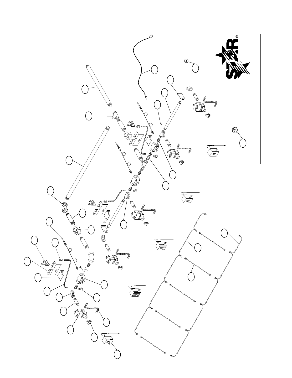
MODEL: 860TS AND 860TSCHS
STAR MANUFACTURING INTERNATIONAL, INC.
SK1882 Rev.- 01-24-02
L
L
L
L
L
8
9
10
13
1
2
6
4
5
16
17
31
32
18
15
11
12
3
23
21
14
22
7
19
20
25
27
26
24
28
29
30
0
3030
Page 37

PARTS LIST October 24, 2011, Rev H
860TS and 860TSCHS Series
Key
Number
1 2K-Z4921 860TS/TSCHS 5 BURNER FLEX TUBE
2
3
4
5 2K-2665 860TS/TSCHS 3 ELBOW 3/8 NPT
6
7
8
9
10 2J-Z4608 860TS/TSCHS 3 PILOT BURNER
11 2A-Y2017 860TS/TSCHS 3 PILOT ORIFICE
12 2K-Z4920 860TS/TSCHS 3 PILOT TUBE FLEX
13 2J-Z4609 860TS/TSCHS 3 THERMOCOUPLE
14 2K-Z4617 860TS/TSCHS 3 REDUCER BUSHING
15 2K-Z5032 860TS/TSCHS 1 INLET PIPE
16 2K-Z5033 860TS/TSCHS 2 UNION
17 2K-Z4618 860TS/TSCHS 4 NIPPLE 3/4 NPT X 2 1/4
18 2K-Z5034 860TS/TSCHS 2 3/4 NPT TEE
19 2J-Z4607 860TS/TSCHS 3 SAFETY VALVE
20 2V-6671 860TS/TSCHS 3 PILOT VALVE
21 2K-Y4403 860TS/TSCHS 6 CLOSE NIPPLE 3/8 NPT
22 2K-9688 860TS/TSCHS 2 TEE 3/8 NPT
23
24
25 G5-824015 860TS/TSCHS 5 WIRE ASSEMBLY #1
26
27
28
29 2K-Y2967 860TS/TSCHS
30 N2-30409 860TS/TSCHS
31 2K-Z4611 860TS/TSCHS 2 ELBOW 3/4 NPT
32
Part
Number
2K-2675 860TS/TSCHS 5 FITTING 3/8 CC X 3/8 MPT
2P-1453 860TS/TSCHS 2 PIPE PLUG
2K-Y5550 860TS/TSCHS 5 NIPPLE 3/8 NPT X 1 1/2
2J-Z4610 860TS/TSCHS 5 SOLENOID VALVE
G5-Z4907 860TS/TSCHS 3 MOUNTING BRACKET
G5-824019 860TS/TSCHS 3 PILOT BRACKET ASSY
G5-824018 860TS/TSCHS 3 FLASH TUBE BRACKET ASSY
2K-Z4612 860TS/TSCHS 2 NIPPLE WITH PRESSURE TAP
2T-Z7440 824TS/TSCHS
PS-Z9318 824TS/TSCHS THERMOSTAT SERVICE KIT manuf. before 8/2005
G5-860017 860TS/TSCHS 1 WIRE ASSEMBLY 860TS “C”
G5-860016 860TS/TSCHS 1 WIRE ASSEMBLY 860TS “L”
2E-Z1858 860TS/TSCHS 1 SWITCH
2K-Z5035 860TS/TSCHS 1 NIPPLE 3/4 NPT X 22 1/2
MODEL
Model Number
Per Unit
5
1 CORD BUSHING
1 CORD SET 6’ LONG
THERMOSTAT
Description
IMPORTANT: WHEN ORDERING, SPECIFY VOLTAGE OR TYPE GAS DESIRED
INCLUDE MODEL AND SERIAL NUMBER IMPORTANT: PAGE 1
Some items are included for illustrative purposes only and in certain OF 1
instances may not be available.
Star International Holdings Inc. Company
Page 38
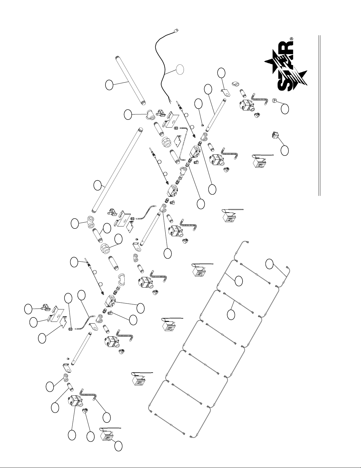
MODEL: 872TS AND 872TSCHS
STAR MANUFACTURING INTERNATIONAL, INC.
SK1881 Rev.- 01-24-02
2
1
6
4
5
8
9
10
13
11
12
16
17
31
32
20
19
18
15
22
14
21
3
23
7
L
1
1
26
27
L
28
29
30
1
L
25
L
L
L
L
L
L
1
1
L
24
L
1
L
0
3232
Page 39

PARTS LIST October 24, 2011, Rev H
872TS and 872TSCHS Series
Key
Number
1 2K-Z4921 872TS/TSCHS 6 BURNER FLEX TUBE
2
3
4
5 2K-2665 872TS/TSCHS 3 ELBOW 3/8 NPT
6
7
8
9
10 2J-Z4608 872TS/TSCHS 3 PILOT BURNER
11 2A-Y2017 872TS/TSCHS 3 PILOT ORIFICE
12 2K-Z4920 872TS/TSCHS 3 PILOT TUBE FLEX
13 2J-Z4609 872TS/TSCHS 3 THERMOCOUPLE
14 2K-Z4617 872TS/TSCHS 3 REDUCER BUSHING
15 2K-Z5032 872TS/TSCHS 1 INLET PIPE
16 2K-Z5033 872TS/TSCHS 2 UNION
17 2K-Z4618 872TS/TSCHS 4 NIPPLE 3/4 NPT X 2 1/4
18 2K-Z5034 872TS/TSCHS 2 3/4 NPT TEE
19 2J-Z4607 872TS/TSCHS 3 SAFETY VALVE
20 2V-6671 872TS/TSCHS 3 PILOT VALVE
21 2K-Y4403 872TS/TSCHS 6 CLOSE NIPPLE 3/8 NPT
22 2K-9688 872TS/TSCHS 3 TEE 3/8 NPT
23
24
25 G5-824015 872TS/TSCHS 6 WIRE ASSEMBLY #1
26
27
28
29 2K-Y2967 872TS/TSCHS
30 N2-30409 872TS/TSCHS
31 2K-Z4611 872TS/TSCHS 2 ELBOW 3/4 NPT
32
Part
Number
2K-2675 872TS/TSCHS 6 FITTING 3/8 CC X 3/8 MPT
2P-1453 872TS/TSCHS 3 PIPE PLUG
2K-Y5550 872TS/TSCHS 6 NIPPLE 3/8 NPT X 1 1/2
2J-Z4610 872TS/TSCHS 6 SOLENOID VALVE
G5-Z4907 872TS/TSCHS 4 MOUNTING BRACKET
G5-824019 872TS/TSCHS 3 PILOT BRACKET ASSY
G5-824018 872TS/TSCHS 3 FLASH TUBE BRACKET ASSY
2K-Z4612 872TS/TSCHS 3 NIPPLE WITH PRESSURE TAP
2T-Z7440 824TS/TSCHS
PS-Z9318 824TS/TSCHS THERMOSTAT SERVICE KIT manuf. before 8/2005
G5-872017 872TS/TSCHS 1 WIRE ASSEMBLY 872TS “C”
G5-872016 872TS/TSCHS 1 WIRE ASSEMBLY 872TS “L”
2E-Z1858 872TS/TSCHS 1 SWITCH
2K-Z5035 872TS/TSCHS 1 NIPPLE 3/4 NPT X 22 1/2
MODEL
Model Number
Per Unit
THERMOSTAT
6
1 CORD BUSHING
1 CORD SET 6’ LONG
Description
IMPORTANT: WHEN ORDERING, SPECIFY VOLTAGE OR TYPE GAS DESIRED
INCLUDE MODEL AND SERIAL NUMBER IMPORTANT: PAGE 1
Some items are included for illustrative purposes only and in certain OF 1
instances may not be available.
Star International Holdings Inc. Company
Page 40

STAR INTERNATIONAL HOLDINGS INC. COMPANY
Star - Holman - Lang - Wells - Bloomeld - Toastmaster
10 Sunnen Drive, St. Louis, MO 63143 U.S.A.
(314) 678-6303
www.star-mfg.com
3434
 Loading...