

Page 1

Star
Manufacturing
International Inc.
10 Sunnen Drive
St. Louis, MO 63143
Phone: (314) 678-6303
Fax: (314) 781-2714
2M-Z20327 Rev. B 11/30/15
Installation
and
Operating
Instructions
ULTRA-MAX GAS RADIANT CHARBROILER
MODELS
8124RCBB, 8136RCBB,
8148RCBB, 8160RCBB, and 8172RCBB
ULTRA-MAX GAS LAVA ROCK CHARBROILER
MODELS
8024CBB, 8036CBB,
8048CBB, 8060CBB, and 8072CBB
WARNING: Improper installation, adjustment,
alteration, service or maintenance can cause
property damage, injury or death. Read
the installation, operating and maintenance
instructions thoroughly before installing or
servicing this equipment.
FOR YOUR SAFETY: Do not store or use
gasoline or other ammable vapors or liquids
in the vicinity of this or any other appliance.
WARNING: This appliance shall be installed
in accordance with current regulations and
used only in well-ventilated space. Refer to
instructions before installing and using this
appliance.
In addition, there should be posted, in a
prominent location, detailed instructions to
be followed in the event the operator smells
gas. Obtain the instructions from the local
gas supplier.
Page 2

SAFETY SYMBOL
Using any part other than genuine Star factory supplied parts relieves the
manufacturer of all liability.
Star reserves the right to change specications and product design without
notice. Such revisions do not entitle the buyer to corresponding changes,
improvements, additions or replacements for previously purchased
equipment.
Due to periodic changes in designs, methods, procedures, policies and
regulations, the specications contained in this sheet are subject to change
without notice. While Star International Holdings Inc., Company exercises
good faith efforts to provide information that is accurate, we are not
responsible for errors or omissions in information provided or conclusions
reached as a result of using the specications. By using the information
provided, the user assumes all risks in connection with such use.
These symbols are intended to alert the user to the presence of
important operating and maintenance instructions in the manual
accompanying the appliance.
RETAIN THIS MANUAL FOR FUTURE REFERENCE
NOTICE
MAINTENANCE AND REPAIRS
Contact your local authorized service agent for service or required maintenance.
Please record the model number, serial number, voltage and purchase date in the area below and have it
ready when you call to ensure a faster service.
Authorized Service Agent Listing
Model No.
Serial No.
Voltage
Purchase Date
Reference the listing provided with the unit
or
for an updated listing go to:
Service Help Desk
Business 8:00 am to 4:30 p.m. Central Standard Time
Hours:
Telephone: (314) 678-6303
Fax: (314) 781-2714
E-mail [email protected]
Website: www.star-mfg.com
Mailing Address: Star International Holdings Inc., Company
10 Sunnen Drive
St. Louis, MO 63143
U.S.A
2
Page 3

HEIGHT
Ultra-Max Gas Charbroiler
DEPTHWIDTH
Gas Inlet
3/4” NPT
4”
Model
Manual
Controls
8124RCBB 4 80,000
8136RCBB 6 120,000
8148RCBB 8 160,000
8160RCBB 10 200,000
8172RCBB 12 240,000
8024CBB 4 80,000
8036CBB 6 120,000
8048CBB 8 160,000
8060CBB 10 200,000
8072CBB 12 240,000
2M-Z20327, Ultra-Max Gas Char-broiler
BTUH Grid Area
603 sq in
(3,890 sq cm)
906 sq in
(5,845 sq cm)
1,209 sq in
(7,800 sq cm)
1,512 sq in
(9,754 sq cm)
1,815 sq in
(11,710 sq cm)
603 sq in
(3,890 sq cm)
906 sq in
(5,845 sq cm)
1,209 sq in
(7,800 sq cm)
1,512 sq in
(9,754 sq cm)
1,815 sq in
(11,710 sq cm)
Waterpan
Specications
Installed Shipped Width Depth Height
RADIANT
196 lbs
(88.9 kg)
273 lbs
(123.8 kg)
358 lbs
(162.3 kg)
441 lbs
(200 kg)
596 lbs
(269.9 kg)
LAVA ROCK
196 lbs
(88.9 kg)
273 lbs
(123.8 kg)
358 lbs
(162.3 kg)
441 lbs
(200 kg)
596 lbs
(269.9 kg)
19.78”
22.26”
24.72”
Approx Weight Dimensions
262 lbs
(118.9 kg)
349 lbs
(158.2 kg)
442 lbs
(200.4 kg)
541 lbs
(245.3 kg)
731 lbs
(330.9 kg)
262 lbs
(118.9 kg)
349 lbs
(158.2 kg)
442 lbs
(200.4 kg)
541 lbs
(245.3 kg)
731 lbs
(330.9 kg)
24”
(61 cm)
36”
(91.4 cm)
48”
(122 cm)
60”
(152.4 cm)
72”
(182.9 cm)
24”
(61 cm)
36”
(91.4 cm)
48”
(122 cm)
60”
(152.4 cm)
72”
(182.9 cm)
30 5/8”
(77.8 cm)
30 5/8”
(77.8 cm)
5 7/16”
IL2511
18”
(45.7 cm)
18”
(45.7 cm)
3
Page 4

CAUTION
GENERAL INSTALLATION DATA
This equipment is designed and sold for commercial use only by personnel trained and experienced
in its operation and is not sold for consumer use in and around the home nor for use directly by the
general public in food service locations.
The Ultra-Max™ series gas charbroiler is equipped for the type of gas indicated on the nameplate
mounted on the front panel. All units are shipped from the factory for use with natural gas. The unit can
easily be converted for use with propane gas: see propane gas.
-IMPORTANTBe sure to remove all paper protection and packing material from unit prior to
lighting.
INSTALL IN NON-COMBUSTIBLE LOCATIONS ONLY! Clearance from noncombustible construction must be 3" minimum from back and sides. For servicing,
6" is recommended from back of unit.
The installation of the Appliance must conform to the NATIONAL FUEL GAS
CODE "ANSI Z223.1 - LATEST EDITION" AND ALL LOCAL GAS COMPANY
RULES AND REGULATIONS.
IN CANADA INSTALLATION SHALL BE IN ACCORDANCE WITH THE
CURRENT CAN/CGA-B149.1 NATURAL GAS INSTALLATION CODE OR CAN/
CGA-B149.2 PROPANE INSTALLATION CODE AND LOCAL CODES WHERE
APPLICABLE.
NOTICE
When this appliance is installed with casters, it must be installed with the casters supplied, a connector
complying with either ANSI Z21.69 or CAN/CGA-6.16 and a quick-disconnect device complying with
either ANSI Z21.41 or CAN1-6.9. It must also be installed with restraining means to guard against
transmission of strain to the connector, as specied in the appliance manufacturer's instructions.
For your protection, we recommend a qualied installing agency install this
appliance. They should be familiar with gas installations and your local gas
requirements. In any case, your gas company should be called to approve the
nal installation.
This appliance, its pressure regulator and its individual shutoff valve must be disconnected from the
gas supply piping system during any pressure testing of that system at test pressures in excess of 1/2
PSIG. This appliance and its pressure regulator must be isolated from the gas supply piping system by
closing its individual manual shutoff valve during any pressure testing of the gas supply piping system
at test pressures equal to or less than 1/2 PSIG.
EXHAUST CANOPY
Open hearth broilers inherently create a good deal of heat and smoke and should be installed under an
efcient exhaust hood with ame proof lters. A vertical distance of not less than 48" shall be provided
between the top of the appliance and lters or any other combustible material. Exhaust installation
must conform to local codes.
AIR SUPPLY
Provisions for adequate air supply must be provided.
2M-Z20327, Ultra-Max Gas Char-broiler
CAUTION
Air for combustion enters from the bottom of the unit. Do not obstruct this area.
4
Page 5
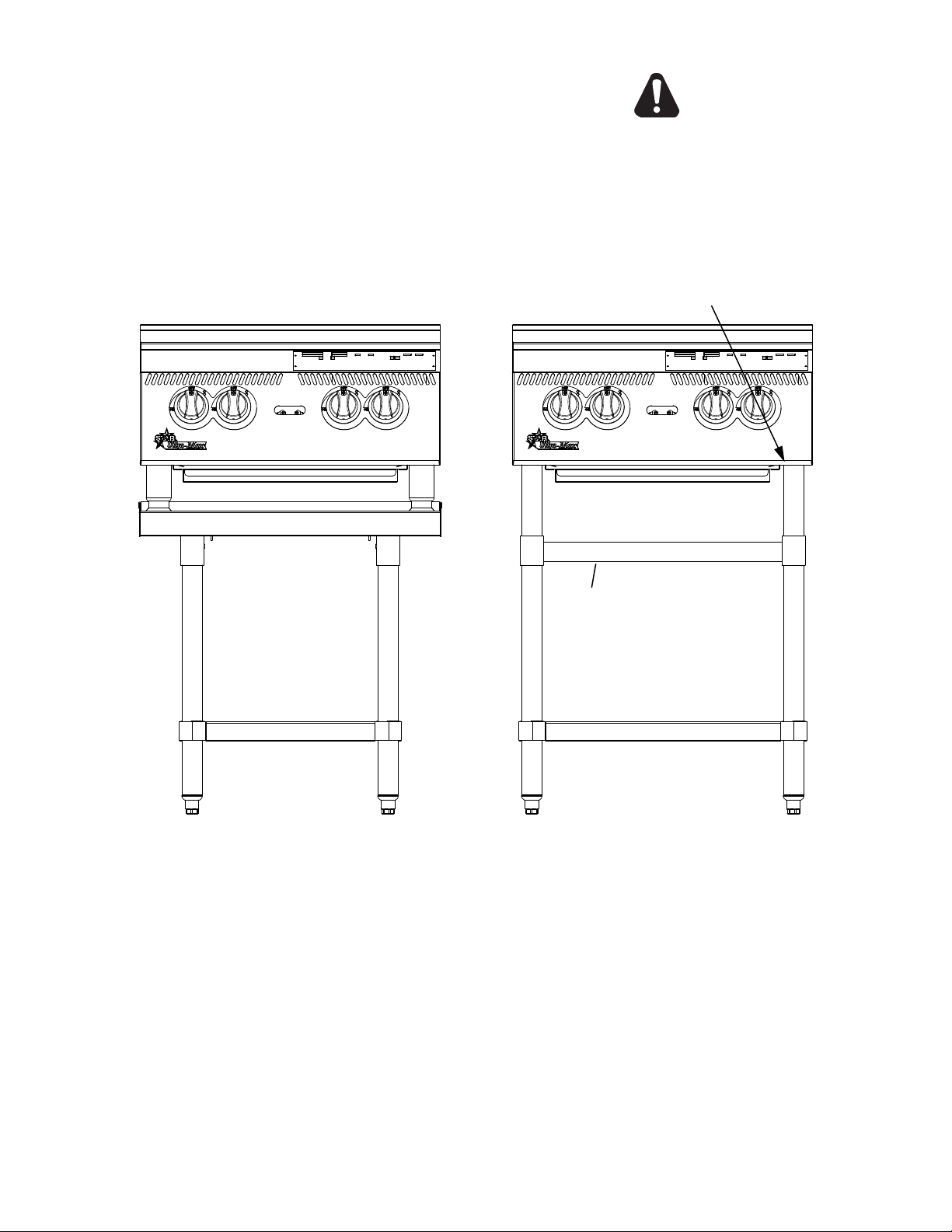
LEVELING UNIT
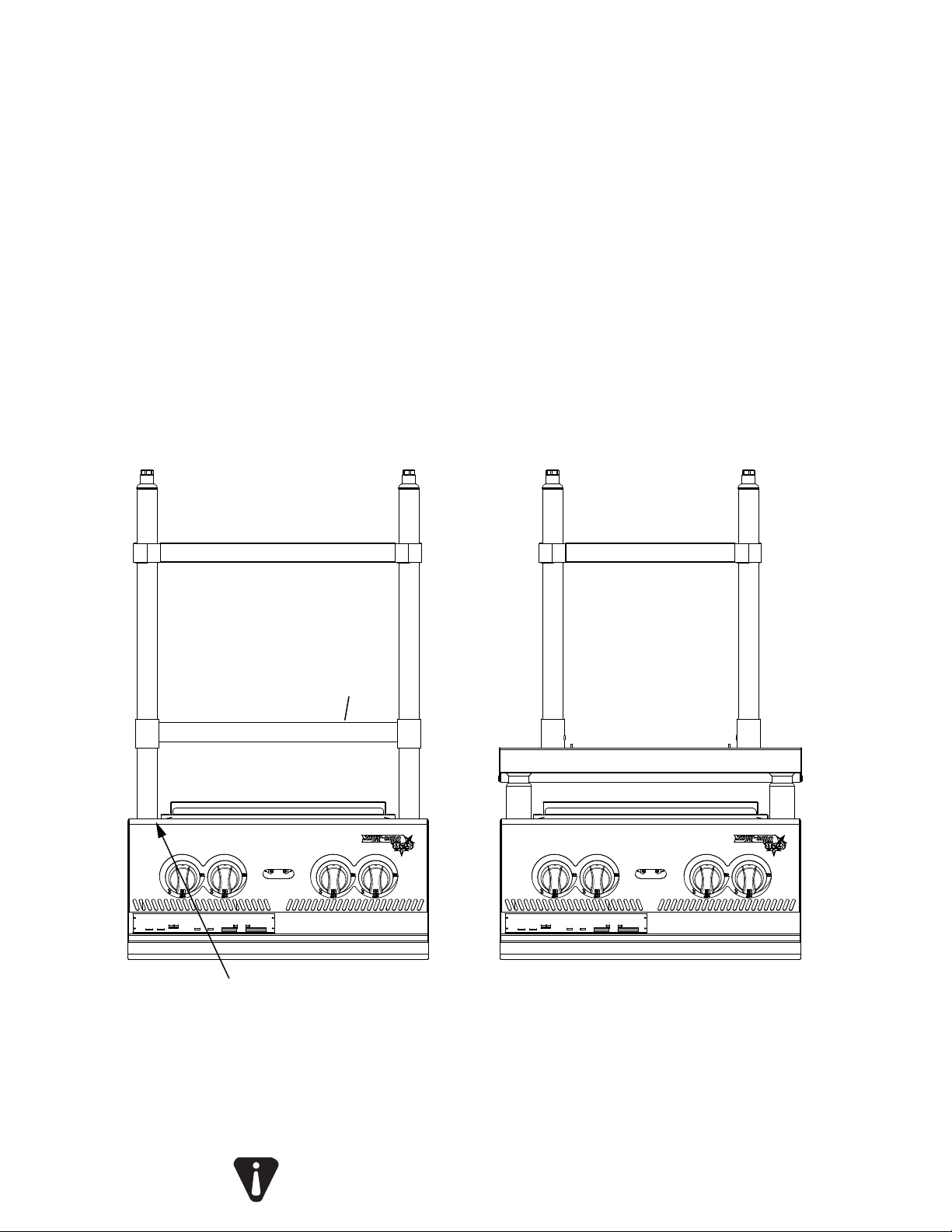
This charbroiler is supplied with 4 feet or oor stand
legs which must be screwed into the body. Unit must be
level. Level unit by adjusting the (4) feet which have an
adjustment of 1-3/4" for accurate and perfect line-up with
other units.
CAUTION
DO NOT INSTALL WITHOUT ATTACHING FEET
OR SUPPLIED STAND LEGS AND SHELF -
DO NOT REMOVE FEET.
SCREW LEGS INTO
MOUNTING NUTS ON BOTTOM
STIFFENING SUPPORTS FOR
8148, 8160 & 8172 MODELS ONLY
FLOOR STAND SHELF
FLOOR STAND MODELCOUNTER TOP MODEL
ON OPTIONAL EQUIPMENT STAND
Caster Kits: Casters can be used with oor stand models or optional equipment stand. For installation, carefully
mark and cut off from the bottom of each leg using a straight cutting saw and de-burr the inside tube wall prior
to installing the caster. Cut leg should measure 19" tube length, not overall length. Casters add about 6-1/4" of
2M-Z20327, Ultra-Max Gas Char-broiler
height to the unit. Be sure to use approved strain relief means for protecting gas line connection. If an appliance
is equipped with casters and is gas connected with a quick connect coupling, all personnel must be aware that
there is a restraint on the appliance and if disconnected for service or cleaning it must be reconnected as originally
installed prior to use.
IL2505
5
Page 6

GENERAL INSTALLATION DATA (continued)
PLACING RADIANTS - RCBB SERIES
After the unit is unpacked and installed, place 1 radiant above each burner. Install each radiant on 2
slots of the rear wall and on 1 pin of the front wall of the liner weld assembly. Refer to the exploded view
in this manual for orientation of the radiants.
PLACING LAVA ROCKS- CBB SERIES
Open the lava rock bags and place rock evenly on the lower internal grates - not the top cooking grates.
Spread the lava rock evenly on the grates approximately 1 layer thick. Do not cover the grates with
more than two layers of lava rock. Do not put more than 5 pounds of rock per foot, or for every two
burners. NOTE: To much rock will deect the heat downward.
GAS PIPING
Gas piping shall be of such size and so installed as to provide a supply of gas sufcient to meet the
full gas input of the appliance. If the appliance is to be connected to existing piping, it shall be checked
to determine if it has adequate capacity. Joint compound shall be used sparingly and only on the male
threads of the pipe joints. Such compounds shall be resistant to the action of L.P. gases. WARNING:
Any loose dirt or metal particles which are allowed to enter the gas lines on this appliance will damage
the valve and affect its operation. When installing this appliance, all pipe and ttings must be free from
all internal loose dirt.
GAS PRESSURE REGULATOR
A convertible pressure regulator is provided with each charbroiler. It should be connected to the inlet pipe
at the rear of the unit. The gas supply is then connected to it. The supply pressure to the regulator is not to
exceed 1/2 PSIG. It is shipped set for 5" water column manifold pressure for use with natural gas.
CAUTION
MANUAL SHUT OFF VALVE
A manual shut off valve should be installed upstream from the manifold and within six feet of the
charbroiler.
CONNECTING GAS SUPPLY LINE
The gas inlet of the charbroiler is sealed at the factory to prevent entry of dirt. Do not remove this seal
until the actual connection is made to the gas supply line.
PROPANE GAS - CONVERSION
This charbroiler is equipped with xed orice hoods and is shipped from the factory for use with natural
gas. To convert to propane gas, install the burner orice hoods, located in the water pan, as follows:
1. Remove grates, radiants and burners.
2. Remove the burner orice hoods (NAT #47) and install the orice hoods (LP #55) supplied.
3. Replace the burners, radiants, and grates.
4. Set manifold pressure to (10) inch water column. A 1/8" pipe plug on the burner manifold can
be removed for attaching a pressure gauge. Remove the slotted, or hex-threaded plug from the
pressure regulator. Invert the plug and re-install. The letters "LP" should now be visible on the
plug. The regulator is now set for 10" (25.4 cm) water column. Attach the conversion label, supplied
with the unit, close to the nameplate.
CHECKING FOR GAS LEAKS
Check entire piping system for leaks. Soap and water solution or other material acceptable for the
purpose, shall be used in locating gas leakage.
2M-Z20327, Ultra-Max Gas Char-broiler
Matches, candle ame or other sources of ignition shall not be used for locating
gas leaks.
PILOT LIGHTING INSTRUCTIONS
The charbroiler is equipped with standing pilots, and should be lit immediately after the gas is turned on.
1. Turn off main valve to unit.
2. Turn off all knobs and pilot valves and wait 5 minutes to clear gas.
3. The pilot lights on this broiler have been pre-set at the factory. Turn the adjustable screw
counterclockwise to open and clockwise to close.
6
Page 7
4. Turn on main valve and light all pilots.
5. Adjust pilot light ames as small as possible, usually about 1/2" high, but high enough to light
burner immediately when burner valve is turned on high.
6. Turn burner knobs to desired setting.
7. To turn burners off, turn knobs off.
BURNER IGNITION AND ADJUSTMENT
1. To ignite burners turn burner valve knob counter clockwise to "ON"position.
2. Slowly decrease openings of air shutters to give a soft blue ame having luminous tips, then slowly
increase openings to a point where the yellow tips disappear and a hard blue ame is obtained.
GENERAL OPERATING INSTRUCTIONS
WATER PAN
The water pan is located at the bottom of the unit, and is easily removed from the front of the unit. 1/4"
of water should be added to the water pan and added as necessary. The water pan helps prevent are
ups and catches grease.
BURNER OPERATION
Each burner is controlled by an individual high-low, on-off valve. A variety of broiling temperatures
may be obtained by turning the burner valve knob to any position between on and off. It is possible
through this arrangement to have a high heat or searing section, while having a low heat nishing or
holding section. For the searing operation, turn the valve counter clockwise for the section to a position
of "ON" or close to it. For holding or nishing, turn the valves closer to the "OFF" position on the dial.
You select the heat pattern you like, and set the valves accordingly. Be sure burners are staying fully
lit when set in low positions.
CAUTION
2M-Z20327, Ultra-Max Gas Char-broiler
LIGHTING
When broiler is rst lit, it will smoke for approximately 20-30 minutes until the preservation oils and
impurities are burned off.
BROILING
Turn valves on and pre-heat unit on "ON" before attempting to broil. You will have to experiment with
the grate settings and the valve settings for your particular food products. Check water pans frequently
and add a sufcient amount of water when necessary. Hot water vapors rising from the water pans and
through the combustion chamber helps reduce are ups. Exercise care when using your broiler.
TILTING THE GRATE
Raise or lower the grate to the next step by lifting the grate at the back of the charbroiler where the
grate rests. Use potholders or gloves to reposition.
CHARBROILERS ARE HOT! NEVER ATTEMPT TO CHANGE THE GRATE
POSITION WHILE FOOD PRODUCTS ARE COOKING. FLARE UPS CAN OCCUR
UNEXPECTEDLY. TURN OFF CHARBROILER, AND ALLOW THE CHARBROILER
TO COOL.
SHUTTING DOWN INSTRUCTIONS
Turn the burner valve knobs to the off position to turn burners off and close manual valve gas shutoff.
CLEANING
Clean regularly. Remove grate section to sink for washing. Brush out carboned particles. Remove and
wash water pan. Wipe exterior surfaces with detergent and a cloth. A non-abrasive cleaner can be
used on caked areas.
LAVA ROCK
Monthly or as needed remove the rock and place in a 5 gallon bucket of water and let sit overnight.
Clean lava grates at this time. Grease and debris will separate from the rock, drain and place the 2"
pieces back into position, refresh with new rock as needed.
7
Page 8
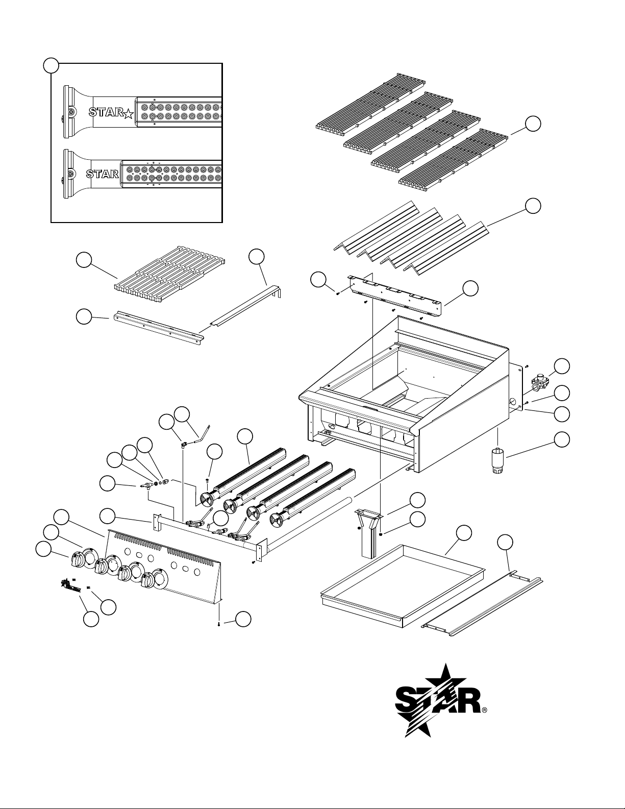
SK2895 Rev. C 11/30/15
25
Older Burner Design,
Replace with PS-Z20939
1
14
15
Current Burner Design
27
26
19
16
17
20
21
22
23
24
29
18
25
2
28
3
4
5
3
6
7
8
9
10
11
12
13
SOME ITEMS ARE INCLUDED FOR
ILLUSTRATIVE PURPOSES ONLY AND IN
CERTAIN INSTANCES MAY NOT BE AVAILABLE
MODEL:
8124RCBB, 8136RCBB, 8148RCBB
8160RCBB, 8172RCBB
8024CBB, 8036CBB, 8048CBB
3
2M-Z20327, Ultra-Max Gas Char-broiler
8124RCBB, 8024CBB
STAR MANUFACTURING INTERNATIONAL, INC.
8
Page 9
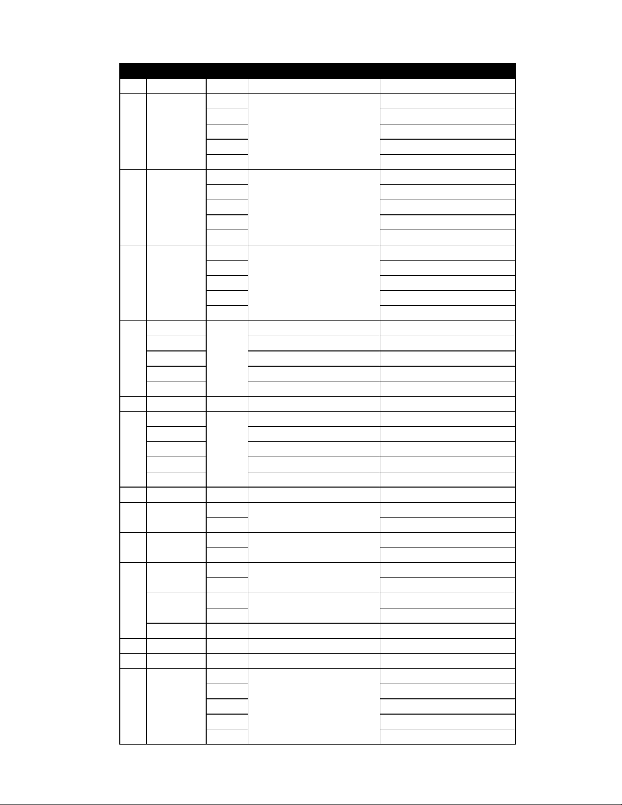
PARTS LIST November 30, 2015, Rev B
8124/8136/8148/8160/8172 Ultra-Max Radiant Gas Charbroiler
8024/8036/8048/8060/8072 Ultra-Max Lava Rock Gas Charbroiler
Model: Ultra-Max Charbroiler Radiant & Lava Rock
Fig No. Part Number Quantity Description Application
2M-Z20327, Ultra-Max Gas Char-broiler
4
6 8136RCBB, 8036CBB
1 2F-Z4692
2 2F-Z4693
3 2C-8833
H5-Z18147
H5-Z18148 REAR BURNER SUPPORT 36 8136RCBB, 8036CBB
4
H5-Z18149 REAR BURNER SUPPORT 48 8148RCBB, 8048CBB
H5-Z18150 REAR BURNER SUPPORT 60 8160RCBB, 8060CBB
H5-Z18151 REAR BURNER SUPPORT 72 8172RCBB, 8072CBB
5 2J-Z4686 1 REGULATOR-3/4 X 3/4 8124CBB
H5-Z4747-1
H5-Z4748 REAR PANEL-36” 8136RCBB, 8036CBB
6
H5-Z4749-1 REAR PANEL-48” 8148RCBB, 8048CBB
H5-Z4750 REAR PANEL-60” 8160RCBB, 8060CBB
H5-Z7796 REAR PANEL-72 8172RCBB, 8072CBB
7 2R-Z19119 4 LEG 4” X 2”D 5/8-16 S.S. 8124CBB
8 H5-824043
9 2C-Z2893
H5-Z4743
10
H5-Z4744
H5-Z4746 2 PAN-60 8160RCBB, 8060CBB
12 2C-8477 4 CLIP .125 PO STL PHOS 8124RCBB
13 2M-Z15805 1 LOGO, ULTRA-MAX 8124CBB
14 I4-Z15484
GRATE CHARBROILER
8 8148RCBB, 8048CBB
10 8160RCBB, 8060CBB
12 8172RCBB, 8072CBB
4
6 8136RCBB
RADIANT-ULTRAMAX
8 8148RCBB
10 8160RCBB
12 8172RCBB
18
20 8136RCBB, 8036CBB
SCREW 8-18X1/2 HEX STL NP
29 8148RCBB, 8048CBB
31 8160RCBB, 8060CBB, 8172RCBB
43 8072CBB
REAR BURNER SUPPORT 24 8124RCBB, 8024CBB
1
REAR PANEL-CB 2’ 8124RCBB, 8024CBB
1
1
NARROW CHUTE WELDMENT
2 8172RCBB, 8072CBB
2
NUT 10-24 HEX STL ZP
4 8172RCBB, 8072CBB
1
PAN-24
2 8148RCBB, 8048CBB
1
PAN-36
2 8172RCBB, 8072CBB
4
6 8136RCBB, 8036CBB
KNOB ASSEMBLY LG GAS KEYB
8 8148RCBB, 8048CBB
10 8160RCBB, 8060CBB
12 8172RCBB, 8072CBB
8124RCBB, 8024CBB
8124RCBB
8124RCBB, 8024CBB
8124RCBB, 8024CBB
8136RCBB, 8036CBB
8124RCBB, 8024CBB
9
Page 10
4
6 8136RCBB, 8036CBB
15 2M-Z15245
H5-Z15939
H5-Z15943 FRONT PANEL 36” 8136RCBB, 8036CBB
16
H5-Z15284 FRONT PANEL 48” 8148RCBB, 8048CBB
H5-Z15926 FRONT PANEL 60” 8160RCBB, 8060CBB
H5-Z15935 FRONT PANEL 72” 8172RCBB, 8072CBB
2K-Z15961
2K-Z15964 MANIFOLD - CHAR 36” 8136RCBB, 8036CBB
17
2K-Z15945 MANIFOLD - CHAR 48” 8148RCBB, 8048CBB
2K-Z15920 MANIFOLD - CHAR 60” 8160RCBB, 8060CBB
2K-Z15921 MANIFOLD - CHAR 72” 8172RCBB, 8072CBB
18 2P-1453 1 PLUG-PIPE 1/8NPT SQ HD
19 2V-Y8832
20 2C-Z17793
21 2I-Z18152
2A-Z17791
22
2A-Z17792
23 2V-6671
DIAL GRAPHIC, MANUAL UM
8 8148RCBB, 8048CBB
10 8160RCBB, 8060CBB
12 8172RCBB, 8072CBB
FRONT PANEL 24” 8124RCBB, 8024CBB
1
MANIFOLD - CHAR 24” 8124CBB, 8024CBB
1
4
6 8136RCBB, 8036CBB
VALVE-MANUAL GAS
8 8148RCBB, 8048CBB
10 8160RCBB, 8060CBB
12 8172RCBB, 8072CBB
4
6 8136RCBB, 8036CBB
ORIFICE LOCKNUT 3/8-27
8 8148RCBB, 8048CBB
10 8160RCBB, 8060CBB
12 8172RCBB, 8072CBB
4
6 8136RCBB, 8036CBB
O-RING SILICONE 3/8x1/2
8 8148RCBB, 8048CBB
10 8160RCBB, 8060CBB
12 8172RCBB, 8072CBB
4
6 8136RCBB, 8036CBB
ORIFICE ELBOW #47 - NAT
8 8148RCBB, 8048CBB
10 8160RCBB, 8060CBB
12 8172RCBB, 8072CBB
4
6 8136RCBB, 8036CBB
8 8148RCBB, 8048CBB
ORIFICE ELBOW #55 - LP
10 8160RCBB, 8060CBB
12 8172RCBB, 8072CBB
4
6 8136RCBB, 8036CBB
VALVE-LINCOLN BRASS#3817
8 8148RCBB, 8048CBB
10 8160RCBB, 8060CBB
12 8172RCBB, 8072CBB
8124CBB, 8024CBB
8124RCBB, 8024CBB
8124RCBB, 8024CBB
8124CBB, 8024CBB
8124RCBB, 8024CBB
8124RCBB, 8024CBB
8124CBB, 8024CBB
10
2M-Z20327, Ultra-Max Gas Char-broiler
Page 11
4
6 8136RCBB, 8036CBB
24 2V-Z17948
2F-Z17447
25
PS-Z20939 AR OLDER BURNER & ORFICE CONV. KIT UNITS WITH OLDER BURNERS
H5-Z16351
H5-Z16352 8036CBB
26
H5-Z16353 8048CBB
H5-Z16354 8060CBB
H5-Z16355 8072CBB
2F-Z7802
27
2F-Z7803
28 H5-Z15283
2C-1492 3 SCREW 8-32X1/4 RHP STL
29
2C-1512 3 SCREW 10-24X3/8 RHP STL
NI 2F-Y7193
PILOT TUBE
8 8148RCBB, 8048CBB
10 8160RCBB, 8060CBB
12 8172RCBB, 8072CBB
4
6 8136RCBB, 8036CBB
BURNER ASSY UM CHAR
8 8148RCBB, 8048CBB
10 8160RCBB, 8060CBB
12 8172RCBB, 8072CBB
1 GRATE SUPPORT - LAVA
1
LAVA ROCK GRATE 10-1/2”
2 8024CBB
2
3 8048CBB
LAVA ROCK GRATE 11-3/8”
5 8060CBB
6 8072CBB
4
6 8036CBB
BURNER COVER
8 8048CBB
10 8060CBB
12 8072CBB
2
3 8034CBB
4 8048CBB
LAVA ROCK 2” 5 LBS BAGS
5 8060CBB
6 8072CBB
8124CBB, 8024CBB
8124RCBB, 8024CBB
8024CBB
8036CBB
8036CBB
8024CBB
COULD BE EITHER OF THESE TWO
P/N
8024CBB
2M-Z20327, Ultra-Max Gas Char-broiler
11
Page 12

Visit our Website at: www.star-mfg.com Email: [email protected]
This unit has been tested for proper operation before leaving our plant to insure delivery of your unit in perfect condition. However, there are instances in which
the unit may be damaged in transit. In the event you discover any type of damage to your product upon receipt, you must immediately contact the transportation
company who delivered the item to you and initiate your claim with same. If this procedure is not followed, it may affect the warranty status of the unit.
All workmanship and material in Star products have a one (1) year limited warranty on parts & labor in the United States and Canada. Such warranty is limited
to the original purchaser only and shall be effective from the date the equipment is placed in service. Star's obligation under this warranty is limited to the repair
of defects without charge, by the factory authorized service agency or one of its sub-agencies. Models that are considered portable (see below) should be taken
to the closest Star service agency, transportation prepaid.
THOROUGHLY INSPECT YOUR UNIT ON ARRIVAL
LIMITED EQUIPMENT WARRANTY
> Star will not assume any responsibility for loss of revenue.
> On all shipments outside the United States and Canada, see International Warranty.
* The warranty period for the Ultra-Max, Hot Plates, Griddles, Charbroilers is (3) years parts & labor.
* The warranty period for the Star-Max, Charbroilers, Griddles, Hot Plates, Fryers & Finishing Oven is (2) years parts & labor.
* The warranty period for the JetStar six (6) ounce & Super JetStar eight (8) ounce series popcorn machines is two (2) years.
* ThewarrantyperiodfortheChrome-MaxGriddlesisve(5)yearsonthegriddlesurface.Seedetailedwarrantyprovidedwithunit.
* The warranty period for Dura-Tec coatings is one year under normal use and reasonable care. This warranty does not apply if damage occurs to
Dura-Teccoatingsfromimpropercleaning,maintenance,useofmetallicutensils,orabrasivecleaners,abrasivepads,productidentiersand
point-of-sale attachments, or any other non-food object tha comes in continuous contact with the roller coating. This warranty does not apply to the
“non-stick” properties of such materials.
> This warranty does not apply to "Special Products" but to regular catalog items only. Star's warranty on "Special Products" is six (6) months on parts
and ninety (90) days on labor.
> This warranty does not apply to any item that is disassembled or tampered with for any purpose other than repair by a Star Authorized Service Center or
the Service Center's sub-agency.
> This warranty does not apply if damage occurs from improper installation, misuse, wrong voltage, wrong gas or operated contrary to the Installation and
Operating instructions.
> This warranty is not valid on Conveyor Ovens unless a "start-up/check-out" has been performed by a Factory Authorized Technician.
Parts that are sold to repair out of warranty equipment are warranted for ninety (90) days. The part only is warranted, the labor to replace the part is NOT warranted.
SERVICES NOT COVERED BY WARRANTY
1. Traveltimeandmileagerenderedbeyondthe50mileradiuslimit
2. Mileage and travel time on portable equipment (see below)
3. Labor to replace such items that can be replaced easily during a daily cleaning
routine, ie; removable kettles on fryers, knobs, grease drawers on griddles, etc.
4. Installation of equipment
5. Damagesduetoimproperinstallation
6. Damages from abuse or misuse
7. Operated contrary to the Operating and Installation Instructions
8. Cleaning of equipment
9. Seasoning of griddle plates
Star will not honor service bills that include travel time and mileage charges for servicing any products considered "Portable" including items listed below.
These products should be taken to the Service Agency for repair:
* TheModel510FD,510FFFryer.
* TheModel526TOAToasterOven.
* TheModelJ4R,4oz.PopcornMachine.
*TheModel518CMA&526CMACheeseMelter.
* TheModel12MC&15MC&18MCPHotFoodMerchandisers.
* TheModel12NCPW&15NCPWNachoChip/PopcornWarmer.
* All Hot Dog Equipment except Roller Grills & Drawer Bun Warmers.
* All Nacho Cheese Warmers except Model 11WLA Series Nacho Cheese Warmer.
* All Condiment Dispensers except the Model HPD & SPD Series Dispenser.
* All Specialty Food Warmers except Model 130R, 11RW Series, and 11WSA Series.
* AllQCS/RCSSeriesToastersexcept Model QCS3 & RCS3 Series.
* All Fast Steamer Models except Direct Connect Series.
The foregoing warranty is in lieu of any and all other warranties expressed or implied and constitutes the entire warranty.
Should you need any assistance regarding the Operation or Maintenance of any Star equipment; write, phone, fax or email our Service Department.
In all correspondence mention the Model number and the Serial number of your unit, and the voltage or type of gas you are using.
PARTS WARRANTY
10. Voltage conversions
11. Gas conversions
12. Pilot light adjustment
13. Miscellaneous adjustments
14. Thermostat calibration and by-pass adjustment
15. Resettingofcircuitbreakersorsafetycontrolsorresetbuttons
16. Replacementofbulbs
17. Replacementoffuses
18. Repairofdamagecreatedduringtransit,delivery,&
PORTABLE EQUIPMENT
FOR ASSISTANCE
installationORcreatedbyactsofGod
ALL:
* Pop-Up Toasters
* Butter Dispensers
* Pretzel Merchandisers
(Model 16PD-A Only)
* Pastry Display Cabinets
* Nacho Chip Merchandisers
* Accessories of any kind
* Sneeze Guards
* Pizza Ovens
(Model PO12 Only)
* Heat Lamps
* Pumps-Manual
2M-4497-2 11/21/14
Page 13

2M-Z20327, Ultra-Max Gas Char-broiler
13
Page 14

2M-Z20327, Ultra-Max Gas Char-broiler
14
non abrasif.
l’aide d’un chiffon et d’un détergent. Sur les surfaces encroûtées, on peut utiliser un produit nettoyant
brosse les particules carbonisées. Enlever et laver le bac à eau. Nettoyer les surfaces extérieures à
Nettoyer le barbecue régulièrement. Enlever la section du grille et la laver dans l’évier. Enlever à la
NETTOYAGE
Pour éteindre les brûleurs, tourner les boutons des brûleurs sur la position de fermeture.
INSTRUCTIONS POUR ÉTEINDRE LE BARBECUE
Page 15
15
BARBECUE ET LE LAISSER SE REFROIDIR.
DES FLAMBÉES PEUVENT SE PRODUIRE À L’IMPROVISTE. ÉTEIGNER LE
GARDE
MISE EN
LA POSITION DU GRIL PENDANT LA CUISSON DES PRODUITS DE VIANDE.
LES BARBECUES SONT BRÛLANTS! NE JAMAIS ESSAYER DE CHANGER
repose le grille. Utiliser des maniques ou des gants pour le repositionner.
Élever ou abaisser le grille à la position suivante en soulevant le grille à l’arrière du barbecue où
2M-Z20327, Ultra-Max Gas Char-broiler
INCLINAISON DU GRILLE
aident à réduire les ambées. Faire attention lors de l’utilisation du barbecue.
d’eau chaude qui s’évaporent des bacs à eau et qui passent à travers la chambre de combustion
viande. Vérier souvent les bacs à eau et ajouter sufsamment d’eau lorsque nécessaire. Les vapeurs
devriez expérimenter avec les réglages du gril et les réglages des boutons selon vos spécialités de
Ouvrir les vannes et préchauffer l’appareil sur «HI» avant de commencer la cuisson sur le gril. Vous
CUISSON SUR LE GRIL
protection et les impuretés brûlent.
Lors du premier allumage du barbecue, il se formera un nuage de fumée jusqu’à ce que les huiles de
ALLUMAGE
que les brûleurs restent ont entièrement allumé quand positionnement en basses positions.
sélectionnez le modèle de la chaleur que vous aimez, et a mis les valves en conséquence. Soyez sûr
d’elle. Pour se tenir ou terminer, tournez les valves plus près de la position de “OFF” sur le cadran. Vous
valve dans le sens contraire des aiguilles d’une montre pour la section à une position de “ON” ou près
section, en ayant une basse chaleur nir ou tenir la section. Pour l’exécution desséchante, tournez la
entre "ON" et "OFF." C'est possible à travers cet arrangement pour avoir une haute chaleur ou brûlant
cuisson sur le gril peut être obtenue en tournant la molette de valve de brûleur à n’importe quelle position
Chaque brûleur est contrôlé par un individu haut bas, sur fermé valve. La variété des températures de
L'OPÉRATION DU BRÛLEUR
les besoins. Le bac à eau aide à prévenir les ambées et attrape la graisse.
L’eau devrait être ajoutée à la casserole de l’eau pour couvrir juste le bottam et être substituée selon
Le bac à eau est situé au bas de l’appareil et il est facile à enlever par la partie avant de l’appareil.
BAC À EAU
INSTRUCTIONS DE FONCTIONNEMENT
jaunes disparaissent et une amme bleue dure est obtenu.
des pointes lumineuses, alors lentement ouvertures de l'augmentation à un point où les pointes
2. Lentement ouvertures de la baisse de volets de l'air à donnez une amme bleue douce qui a
aiguilles d’une montre à la position de “ON.”
1. Pour mettre à feu les brûleurs tournent la molette de valve de brûleur dans le sens contraire des
IGNITION DU BRÛLEUR ET AJUSTEMENT
7. Pour éteindre les brûleurs, fermer les boutons.
6. Tourner les boutons des brûleurs sur le réglage désiré.
immédiatement quand la valve du brûleur est allumée haut.
5. Ajustez des ammes de la lumière pilotes aussi petit que possible, mais haut assez allumer le brûleur
4. Ouvrir le bouton principal et allumer les veilleuses.
contraire des aiguilles d’une montre pour s’ouvrir et dans le sens des aiguilles d’une montre à la n.
3. Les lampes témoin sur ce grilleur ont été pré-établies à l’usine. Tournez la vis réglable dans le sens
2. Éteignez tous les boutons et valves du pilote et attendez 5 minutes éclaircir du gaz.
1. Éteignez la principale valve à unité.
ouvert.
Le barbecue est équipé de veilleuses stationnaires et il faut l’allumer dès que le bouton de gaz est
INSTRUCTIONS CONCERNANT LES VEILLEUSES D’ALLUMAGE
Page 16

2M-Z20327, Ultra-Max Gas Char-broiler
16
GARDE
d’allumage.
MISE EN
Ne pas utiliser d’allumettes, la amme d’une chandelle ou d’autres sources
et d’eau ou une autre matière acceptable pour ce but.
Vérier l’étanchéité de toute la tuyauterie. Pour vérier l’étanchéité, il faut utiliser une solution de savon
LA VÉRIFICATION LE GAZ FUIT
(10 po.) de colonne d’eau. Apposez l'étiquette de conversion a coté de la plaque d'identication.
doivent être maintenant visibles sur le bouchon. Le régulateur est maintenant réglé pour 25,4 cm
ou leté hexagonal du régulateur de pression. Inverser le bouchon et le réinstaller. Les lettres "LP"
tuyau de 1/8 po. du collecteur du brûleur pour y attacher un manoMètre.Enlever le bouchon entaillé
4. Régler la pression d’admission sur (10) pouces de colonne d’eau. On peut enlever un bouchon de
3. Substituez les brûleurs, les éléments chauffants, et les grilles.
2. Enlever les orices de brûleurs et installer les orices fournis.
1. Retirez les grilles, les éléments chauffants et les brûleurs.
l’eau, comme suit:
Pour convertir en gaz de propane, installez les capots d’orice de brûleur, situés dans la casserole de
Ce barbecue est équipé d’orices xes et il est expédié de l’usine prêt pour l’utilisation au gaz naturel.
GAZ PROPANE - CONVERSION
cette protection que juste avant d’effectuer le raccord à la canalisation de gaz.
L’admission de gaz du barbecue est scellée en usine an d’empêcher l’entrée des impuretés. N’enlever
RACCORD DE LA CANALISATION DE GAZ
Il faut installer une vanne d’arrêt manuelle en amont du collecteur et à six pieds près du barbecue.
VANNE D’ARRÊT MANUELLE
expédié réglé pour une pression d’admission de 5 po. de colonne d’eau.
d’approvisionnement au régulateur ne doit pas excéder 1/2 PSIG. Pour l’utilisation au gaz naturel, il est
tuyau d’admission à l’arrière de l’appareil. L’alimentation de gaz y est raccordée. La pression
Chaque barbecue est fourni avec un régulateur de pression convertible. Il doit être raccordé au
RÉGULATEUR DE PRESSION DU GAZ
tous les tuyaux et raccords doivent être exempts de toute impureté interne libre.
cet appareil endommagera la vanne et en affectera le fonctionnement. Lors de l’installation de cet appareil,
AVERTISSEMENT : Toute impureté libre ou particule métallique qui entre dans les canalisations de gaz de
les letages mâles des raccords à tuyaux. Ces composés doivent résister à l’action des gaz propanes.
si elle a la capacité nécessaire. Il ne faut utiliser le composé combiné que modérément et seulement sur
l’appareil. S’il faut raccorder l’appareil à la tuyauterie existante, il faut vérier cette dernière pour déterminer
alimentation sufsante de gaz pour répondre aux exigences d’admission de pleine puissance dans
La taille de la tuyauterie à gaz et la façon dont elle est installée doivent être telles qu’elle fournisse une
TUYAUTERIE À GAZ
mettre supérieur à 5 Livres de rock par pied.
couche épaisse. Ne pas couvrir les grilles avec supérieur à deux couches de rocher de lave. N’ a pas
- pas la cuisine de sommet grince. Etaler le rocher de lave également sur les grilles approximatifment 1
Ouvert les sac de rocher de lave et le rocher d’endroit également sur les grilles internes plus basses
PLACEMENT DE LA ROCHE DE LAVE - CBB SÉRIE
soudure du paquebot. Faites référence à la vue explosée dans ce manuel pour orientation du radiants.
chaque radiant sur 2 fentes du mur arrière et sur 1 épingle du mur de devant de l'assemblée de la
Après que l'unité soit déballée et est installée, placez-en 1 radiant au-dessus de chaque brûleur. Installez
PLAÇANT RADIANTS - RCBB SÉRIE
Page 17
17
Vissez les jambes dans des
installé avant l’utilisation.
2M-Z20327, Ultra-Max Gas Char-broiler
contrainte sur l’appareil et si débranché pour le service ou le nettoyage qu’il doit être rebranché comme initialement
des roulettes et est gaz lié à un rapide relient le couplage, tout le personnel doit se rendre compte qu’il y ait une
d’utiliser des moyens approuvés de passe-ls pour protéger la connexion de ligne de gaz. Si un appareil est équipé
mesurer 19“ longueur de tube, longueur hors-tout. Les roulettes ajoutent environ 6-1/4“ de taille à l’unité. Soyez sûr
et un de-burr droits de découpage le mur intérieur de tube avant d’installer la roulette. La jambe de coupe devrait
facultatif. Pour d’installation la marque soigneusement et découpé le de bas de chaque jambe en utilisant une scie
Lots de roulettes: Des roulettes peuvent être utilisées avec les modèles de stand de plancher ou le stand de matériel
IL2505-FR
Sur le Stand Facultatif de Matériel
Modèle de Stand de PlancherContre- Modèle Supérieur
Étagère De Stand De Plancher
8160 et 8172 modèles seulement
Raidissant des supports sur 8148,
GARDE
MISE EN
écrous de support sur le bas
FOURNIES DE STAND.
PIEDS OU DES JAMBES ET L'ETAGERE
N’INSTALLEZ PAS SANS ATTACHER ES
alignement exact et parfait avec d’autres appareils.
les (4) pieds qui ont un réglage de 1-3/4 po., en vue d’un
L'unité doit être niveau. Équilibrer l’appareil en ajustant
stand de plancher qui doivent être vissés dans le corps.
Ce charbroiler est assuré avec 4 pieds ou jambes de
ÉQUILIBRAGE DE L’APPAREIL
Page 18
18
2M-Z20327, Ultra-Max Gas Char-broiler
GARDE
cette section.
MISE EN
L’air nécessaire à la combustion entre par le bas de l’appareil. Ne bas boucher
Les vivres pour provision de l'air adéquate doivent être fournis.
LA PROVISION DE L'AIR
matière combustible. L'installation du gaz d'échappement doit conformer aux codes locaux.
verticale de pas moins que 48 " seront fournis entre le sommet de l'appareil et ltres ou toute autre
installés sous un capuchon du gaz d'échappement effectif avec amme ltres insensibles. Une distance
Les grils du foyer ouverts créent beaucoup de chaleur et fumée fondamentalement et devraient être
ÉPUISEZ LE BALDAQUIN
pression de la tuyauterie d’alimentation de gaz à des pressions égales à ou de moins que ½ PSIG.
tuyauterie d’alimentation du gaz en fermant sa vanne d’arrêt manuelle individuelle lors des essais de
pressions en dessus de ½ PSIG. Cet appareil et son régulateur de pression doivent être isolés de la
de la tuyauterie d’alimentation du gaz lors des essais de pression de la tuyauterie en question à des
Cet appareil, son régulateur de pression et ses vannes d’arrêt individuelles doivent être débranchés
En tout cas, il faut appeler votre société du gaz pour l’approbation de l’installation nale.
d’installation qualiée. Ils doivent connaître les installations de gaz et vos exigences de gaz locales.
Pour votre propre protection, on vous recommande de faire installer cet appareil par une agence
les instructions du constructeur d’appareils.
moyens retenants de garder contre la transmission de la contrainte au connecteur, comme indiqué dans
rapide étant conforme à la norme ANSI Z21.41 ou au CAN1-6.9. Il doit également être installé avec des
fournies, un connecteur étant conforme à la norme ANSI Z21.69 ou au CAN/CGA-6.16 et à un dispositif
NOTIFICATION: Quand cet appareil est installé avec des roulettes, il doit être installé avec les roulettes
GARDE
MISE EN
AU PROPANE CAN/CGA-B149.2 ET AUX CODES LOCAUX, LE CAS ÉCHÉANT.
D’INSTALLATION AU GAZ NATUREL CAN/CGA-B149.1 OU AU CODE D’INSTALLATION
AU CANADA, L’INSTALLATION DOIT ÊTRE CONFORME AU CODE COURANT
RÈGLES ET RÉGLEMENTATIONS DE LA COMPAGNIE DE GAZ LOCALE.
"ANSI Z223.1 - TOUTE DERNIÈRE ÉDITION" DES ÉTATS-UNIS ET À TOUTES LES
L’installation de l’appareil doit se conformer au CODE NATIONAL DE GAZ COMBUSTIBLE
du dos de l’unité.
construction de non-combustible doit être 3“ minimum dos et côtés. Pour entretenir, 6“ est recommandés
NE L’INSTALLER QUE DANS UN ENDROIT NON COMBUSTIBLE ! Le dégagement avec la
de l’unité avant l’éclairage.
Soyez sûr d’enlever tout le matériel de papier de protection et d’emballage à partir
-IMPORTANT-
naturel. Il est facile de convertir l’appareil en vue de l’utilisation au gaz propane : voir le gaz propane.
montée sur le panneau avant. Tous les appareils sont expédiés de l’usine pour l’utilisation au gaz
Le barbecue de la série Ultra-Max est équipé pour le type de gaz indiqué sur la plaque du constructeur
endroits de pique-nique.
sachant l’utiliser et il n’est pas vendu pour l’utilisation à la maison, ni pour l’usage du public dans les
Cet équipement n’est conçu et vendu que pour l’utilisation commerciale par le personnel formé et
GARDE
MISE EN
DONNÉES GÉNÉRALES D’INSTALLATION
Page 19

2
Date d’achat
Voltage
Pour une liste mise à jour voir :
Ou
Voir la liste pourvue avec l’appareil
Agent de service autorisé
AVIS
N° de série
N° de modèle
requise ci-dessous pour référence rapide.
modèle, le numéro de série, le voltage et la date d’achat pour un service plus rapide. Entrez l’information
Contactez votre détaillent local pour les réparations ou l’entretien requis. Assurez-vous d’avoir le numéro de
ENTRETIEN ET RÉPARATIONS
l’utilisateur assume tous les risques en relation avec telle utilisation.
suite de l’utilisation des spécications. En utilisant le renseignement pourvu,
ou les omissions dans le renseignement pourvu ou les conclusions tirées à la
fournir le renseignement correct, STAR n’est pas responsable pour les erreurs
de changer sans préavis. Quoique STAR Manufacturing exerce la bonne foi de
et régulations, les spécications contenues dans ce manuel sont susceptibles
Dû aux modications périodiques de dessins, méthodes, procédures, règles
l’équipement acheté préalablement.
les changements, améliorations, ajouts ou remplacements correspondants pour
sans préavis. Ces changements ne donnent pas le droit à l’acheteur d’obtenir
Star se réserve le droit de changer les spécications et la conception du produit
ricant de toute responsabilité.
L’utilisation de toute pièce autre que les pièces d’origine STAR dégage le fab-
CONSERVEZ CE MANUEL POUR RÉFÉRENCE FUTURE
dans le manuel qui accompagne l’appareil.
instructions d’utilisation ou d’entretien importantes contenues
Ces symboles sont utilisés pour souligner à l’utilisateur les
SYMBOLE DE SÉCURITÉ
Page 20
fournisseur local de gaz.
sent le gaz. Obtenez les instructions du
détaillées d’être suivi en cas que l’opérateur
emplacement en avant, des instructions
En outre, là devrait être signalé, dans un
d’installer et utiliser cet appareil.
aéré. Référez-vous aux instructions avant
et utilisé seulement dans l’espace bieninstallé selon des règlements actuels
AVERTISSEMENT: Cet appareil sera
8048CBB, 8060CBB, et 8072CBB
8024CBB, 8036CBB,
MODELES
imité de ceci ou d’aucun autre appareil.
vapeurs ou liquides inammables à proxou n’utilisez pas l’essence ou d’autres
POUR VOTRE SÛRETÉ: N’enregistrez pas
d’installer ou entretenir ce matériel.
et d’entretien complètement avant
les instructions d’installation, d’opération
matériels, des dommages ou la mort. Lisez
l’entretien peuvent causer des dégats
le réglage, le changement, le service ou
AVERTISSEMENT: L’installation inexacte,
2M-Z20327 Rev. B 11/30/2015
et d’opération
d’installation
Instructions
ULTRA-MAX
BARBECUE A GAZ ROCHE DE LAVE
8148RCBB, 8160RCBB, et 8172RCBB
8124RCBB, 8136RCBB
MODELES
BARBECUE A GAZ RAYONNANT ULTRA-MAX
Fax: (314) 781-2714
Phone: (314) 678-6303
St. Louis, MO 63143
10 Sunnen Drive
International Inc.
Manufacturing
Star
 Loading...