

Page 1
®
ELECTRIC
GRIDDLES
MODELS
724T, 736T, 748T, 760T, 772T
CHROME MODELS
724TCHS, 736TCHS, 748TCHS, 760TCHS, 772TCHS
Installation and
724T
Operation
Instructions
2M-Z8514 Rev. D 3/1/07
MODELS 760T- & 772T-
Not approved for Canada
ANSI/NSF 4
1
Page 2

SAFETY SYMBOL
Using any part other than genuine Star factory supplied parts relieves the
manufacturer of all liability.
Star reserves the right to change specifi cations and product design without
notice. Such revisions do not entitle the buyer to corresponding changes,
improvements, additions or replacements for previously purchased
equipment.
Due to periodic changes in designs, methods, procedures, policies and
regulations, the specifi cations contained in this sheet are subject to change
without notice. While Star Manufacturing exercises good faith efforts to provide
information that is accurate, we are not responsible for errors or omissions
in information provided or conclusions reached as a result of using the
specifi cations. By using the information provided, the user assumes all risks in
connection with such use.
These symbols are intended to alert the user to the presence of
important operating and maintenance instructions in the manual
accompanying the appliance.
RETAIN THIS MANUAL FOR FUTURE REFERENCE
NOTICE
MAINTENANCE AND REPAIRS
Contact your local authorized service agent for service or required maintenance. Please record the model
number, serial number, voltage and purchase date in the area below and have it ready when you call to
ensure a faster service.
Model No.
Serial No.
Voltage
Purchase Date
Authorized Service Agent
Reference the listing provided with the unit
or
for an updated listing go to:
The Star Service Help Desk
Business 8:00 am to 4:30 p.m. Central Standard Time
Hours:
Telephone: (800) 807-9054 Local (314) 781-2777
Fax: (800) 396-2677 Local (314) 781-2714
E-mail [email protected]
Website: www.star-mfg.com
Mailing Address: Star Manufacturing International Inc.
10 Sunnen Drive
St. Louis, MO 63143
U.S.A
2
2
Page 3

CAUTION
This equipment is designed and sold for commercial use only by personnel trained and
experienced in its operation and is not sold for consumer use in and around the home nor for
use directly by the general public in food service locations. For equipment to be used by the
general public, please contact the factory.
INSTALLATION
The griddles are equipped for the voltage indicated on the nameplate mounted on the front
panel. They will operate on alternating current (AC) only.
WARNING
DO NOT CONNECT TO DIRECT CURRENT (DC).
The installation of the electric griddle should conform to the:
NATIONAL ELECTRIC CODE AND ALL LOCAL ELECTRIC CODES AND
ORDINANCES AND THE LOCAL ELECTRIC COMPANY RULES AND
REGULATIONS
For your protection we recommend that a qualifi ed electrician install this griddle. He
should be familiar with electrical installations and all electric codes. Proper connections
and power supply are essential for effi cient performance. The external wiring should be
in conduit or an approved type of fl exible cable suitable for operation at the temperature
indicated on the wiring diagram, and of a proper size to carry the load. The supply circuit
should be properly fused and equipped with a means of disconnecting, as required by
local electrical code. THE BODY OF THE GRIDDLE SHOULD BE GROUNDED (DO NOT
GROUND TO A GAS SUPPLY LINE).
GENERAL OPERATING PROCEDURES
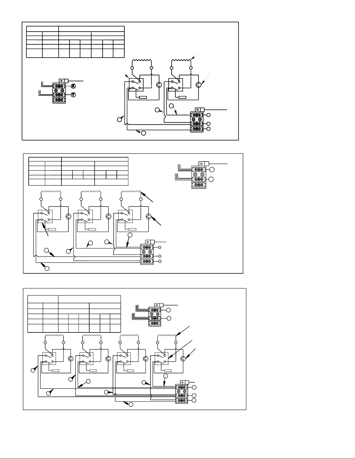
The Ultra-Max series electric griddles may be wired for operation in the fi eld for either 1-phase
or 3-phase power supplies by making line connections at the junction box(es) located at the
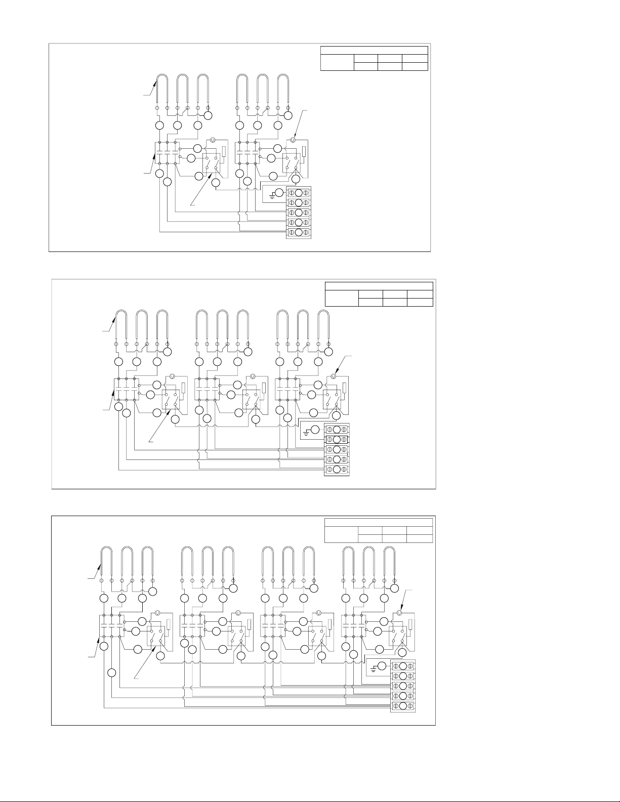
rear of the unit. Models 724T-230/400V, 736T-230/400V & 748T-230/400V, should be wired for
3-phase power supply only. Two junction boxes are provided on the 760T & 772T for making
line connections.
CONNECTING POWER SUPPLY
Detach cover on junction box at rear of unit. There is a terminal block for the supply connection
in the junction box. Wires can be rerouted in the terminal block for 3phase hook-up. See wiring
diagrams and model voltage on unit panel
LOCATING AND LEVELING THE UNIT
Do not install the unit closer than 1-inch from a side wall and/or closer than 1-inch from a rear
wall. Make sure the unit is properly ventilated. Level unit by adjusting the (4) feet which have
an adjustment of 1-3/4” (43.75mm) for accurate leveling and perfect line-up with other UltraMax series units.
3
Page 4

SEASONING THE GRIDDLE HEATING SURFACE
Before initial use, clean the griddle surface thoroughly with hot soap and water. See Griddle
care on page 4 for further information. After the griddle has been thoroughly cleaned, it should
be seasoned to prevent food from sticking. Before using and after each thorough scouring,
season the griddle heating surface in the following manner.
1. Remove any shipping material from the cooking surface and thouroughly clean the entire
grill with hot soap and water.
2. Turn temperature control dials to 350°F (177°C).
3. Using a clean cloth, not a spatula, brush a thin fi lm of cooking oil over the griddle cooking
surface. This fi lm should remain on the hot griddle surface for half an hour.
4. Remove the excess oil and wipe clean.
5. Apply another fi lm of cooking oil over the hot cooking area for another half hour and again
remove excess oil and wipe clean. The griddle surface should now be ready for use.
Even with careful seasoning, food may, to some extent, stick to the griddle cooking surface
until the griddle plate is broken in.
TEMPERATURE CONTROL
The temperature controls are combination “ON/OFF” switches and thermostats. Turning the
dial knob automatically maintains the selected heat range.
The Ultra-Max electric griddle line has one thermostat for every 12” (30cm) section of griddle
that operates independently of one another. Each thermostat controls the section of the griddle
above it and may be set at different temperatures as desired.
COOKING
Set the thermostat dial knob at the temperature desired. After a short pre-heating period, the
thermostat will automatically maintain the selected temperature.
IDLING
During idle periods, to save on operating costs, lower the temperature setting of the thermostat
to about 250°F (121°C). It is not necessary to maintain cooking temperature during idle periods,
as the griddle can quickly be reheated to the desired temperature.
SIGNAL LIGHTS
Each thermostat has its own signal light which indicates when the unit’s control knob is in the
on position. Cooking surface will be hot when the control knob is in this position.
GRIDDLE CARE (NON-CHOME SURFACES)
It takes very little time and effort to keep the griddle attractive and performing at top effi ciency.
If grease is permitted to accumulate, it will form a gummy cake and then carbonize into a
hard substance which is extremely diffi cult to remove. To prevent this condition, the following
suggestions for cleanliness should be followed:
1. After each use, scrape the griddle with a scraper or fl exible spatula to remove excess
grease and food. A waste drawer is provided for the drippings. If there is an accumulation
of burned on grease and food, the griddle should be thoroughly scoured and re-seasoned.
Use pumice or griddle stone while the griddle is warm. Do not use steel wool because of
the danger of steel slivers getting into the food.
2. Daily, use a clean cloth and a good non-abrasive cleaner to clean the stainless steel body
of the griddle. Wipe the polished front with a soft cloth.
3. At least once a day, remove the waste drawer and wash in the same way as an ordinary
cooking utensil. The drawers are removed by pulling forward until they are released from
their track.
4
Page 5

GRIDDLE CARE (CHROME SURFACES)
(Chrome surface griddles are marked with “CHS” at the end of the model number designation on
the nameplate.) It takes very little time and effort to keep this Industrial Chrome griddle surface
sparkling clean and performing at top effi ciency. DO NOT allow grease to accumulate as it will
carbonize and become diffi cult to remove. To prevent this condition, the following cleaning
suggestions should be followed:
1. Remove excess oil and food regularly with a 4” (100mm) wide razor sharp type scraper
and wipe surface with a damp cloth if desired.
2. Following the scraping, for end of the day cleaning, a damp cloth and a non-silicated,
non-abrasive, non-chlorinated cleaner such as Bon-Ami may be used to wipe surface
clean, followed by wiping with clean wet cloth.
3. Follow steps 2 and 3 from Griddle Care (Non- Chrome Surfaces).
CAUTION
ON CROME SURFACES:
1. Never use pumice, griddle stones, or abrasives on the surface.
2. Never strike the griddle surface with a sharp instrument or spatula edge.
3. Never use steel wool.
4. Never use commercial liquid grill cleaner on the griddle surface.
5. Abusing the surface voids the warranty.
GREASE DRAWER
A grease drawer is located at the front can be removed for cleaning by pulling drawer forward.
This drawer contains hot grease and should be checked and emptied when necessary or at
least once a day.
CAUTION
EXERCISE EXTREME CARE IN HANDLING THE GREASE DRAWER
CONTAINING HOT GREASE.
MAINTENANCE AND REPAIRS
Contact the factory, a service representative, or a local service company for service or required
maintenance.
5
Page 6

Visit our Website at: www.star-mfg.com Email: [email protected]
This unit has been tested for proper operation before leaving our plant to insure delivery of your unit in perfect condition. However, there are instances in
which the unit may be damaged in transit. In the event you discover any type of damage to your product upon receipt, you must immediately contact the
transportation company who delivered the item to you and initiate your claim with same. If this procedure is not followed, it may affect the warranty status of
the unit.
All workmanship and material in Star products have a one (1) year limited warranty on parts & labor in the United States and Canada. Such warranty is limited
to the original purchaser only and shall be effective from the date the equipment is placed in service. Star's obligation under this warranty is limited to the repair
of defects without charge, by the factory authorized service agency or one of its sub-agencies. Models that are considered portable (see below) should be taken
to the closest Star service agency, transportation prepaid.
THOROUGHLY INSPECT YOUR UNIT ON ARRIVAL
LIMITED EQUIPMENT WARRANTY
> Star will not assume any responsibility for loss of revenue.
> On all shipments outside the United States and Canada, see International Warranty.
* The warranty period for the JetStar six (6) ounce & Super JetStar eight (8) ounce series popcorn machines is two (2) years.
* The warranty period for the Chrome-Max Griddles is ¿ ve (5) years on the griddle surface. See detailed warranty provided with unit.
* The warranty period for TeÀ on/Dura-Tec coatings is one year under normal use and reasonable care. This warranty does not apply if damage occurs to
TeÀ on/Dura-Tec coatings from improper cleaning, maintenance, use of metallic utensils, or abrasive cleaners, abrasive pads, product identi¿ ers and
point-of-sale attachments, or any other non-food object tha comes in continuous contact with the roller coating. This warranty does not apply to the
“non-stick” properties of such materials.
> This warranty does not apply to "Special Products" but to regular catalog items only. Star's warranty on "Special Products" is six (6) months on parts
and ninety (90) days on labor.
> This warranty does not apply to any item that is disassembled or tampered with for any purpose other than repair by a Star Authorized Service Center or
the Service Center's sub-agency.
> This warranty does not apply if damage occurs from improper installation, misuse, wrong voltage, wrong gas or operated contrary to the Installation and
Operating instructions.
> This warranty is not valid on Conveyor Ovens unless a "start-up/check-out" has been performed by a Factory Authorized Technician.
Parts that are sold to repair out of warranty equipment are warranted for ninety (90) days. The part only is warranted. Labor to replace the part is chargeable to
the customer.
1. Travel time and mileage rendered beyond the 50 mile radius limit
2. Mileage and travel time on portable equipment (see below)
3. Labor to replace such items that can be replaced easily during a daily cleaning
routine, ie; removable kettles on fryers, knobs, grease drawers on griddles, etc.
4. Installation of equipment
5. Damages due to improper installation
6. Damages from abuse or misuse
7. Operated contrary to the Operating and Installation Instructions
8. Cleaning of equipment
9. Seasoning of griddle plates
Star will not honor service bills that include travel time and mileage charges for servicing any products considered "Portable" including items listed below.
These products should be taken to the Service Agency for repair:
* The Model 510FD Fryer.
* The Model 526TOA Toaster Oven.
* The Model J4R, 4 oz. Popcorn Machine.
* The Model 518CMA & 526CMA Cheese Melter.
* The Model 12MC & 15MC & 18MCP Hot Food Merchandisers.
* The Model 12NCPW & 15NCPW Nacho Chip/Popcorn Warmer.
* All Hot Dog Equipment except Roller Grills & Drawer Bun Warmers.
* All Nacho Cheese Warmers except Model 11WLA Series Nacho Cheese Warmer.
* All Condiment Dispensers except the Model HPD & SPD Series Dispenser.
* All Specialty Food Warmers except Model 130R, 11RW Series, and 11WSA Series.
* All QCS/RCS Series Toasters except Model QCS3 & RCS3 Series.
SERVICES NOT COVERED BY WARRANTY
PARTS WARRANTY
10. Voltage conversions
11. Gas conversions
12. Pilot light adjustment
13. Miscellaneous adjustments
14. Thermostat calibration and by-pass adjustment
15. Resetting of circuit breakers or safety controls or reset buttons
16. Replacement of bulbs
17. Replacement of fuses
18. Repair of damage created during transit, delivery, &
installation OR created by acts of God
PORTABLE EQUIPMENT
ALL:
* Pop-Up Toasters
* Butter Dispensers
* Pretzel Merchandisers
(Model 16PD-A Only)
* Pastry Display Cabinets
* Nacho Chip Merchandisers
* Accessories of any kind
* Sneeze Guards
* Pizza Ovens
(Model PO12 Only)
* Heat Lamps
* Pumps-Manual
The foregoing warranty is in lieu of any and all other warranties expressed or implied and constitutes the entire warranty.
FOR ASSISTANCE
Should you need any assistance regarding the Operation or Maintenance of any Star equipment; write, phone, fax or email our Service Department.
In all correspondence mention the Model number and the Serial number of your unit, and the voltage or type of gas you are using.
6
Part# 2M-4497-2 12/06 RMS
Page 7
SINGLE PHASE
208V 240V
8.7 KW
AWG #8AWG
8.7 KW 8.7 KW 8.7 KW
X-Y X-Y
41.8 36.3
#6
NOMINAL AMPS PER LINE 3 PH.
208V-3 PHASE
X
20.9
AWG
#12
Y Z
AWG
#8
XY Z
18.120.936.2 31.3 18.1
AWG #8AWG
AWG
#12
#12
240V-3PHASE
FOR SUPPLY CONNECTIONS USE COPPER WIRE ONLY, SUITABLE FOR AT
LEAST 90°C (194°F). USE GAUGE SHOWN OR LARGER.
AWG
#12
HEATING ELEMENT
NOTE: Wattage is 4.35 kw
per heated zone. See unit
nameplate on front panel
for correct supply voltage.
1,3
2,4
TERMINAL BLOCK
2M-Z8445
SINGLE PHASE SUPPLY
208V
13.05 KW
13.05 KW 13.05 KW 13.05 KW
X-Y X-Y
62.7 54.4
6
2M-Z8446
5
GROUND WIRE
TO CONVERT TO 3 PHASE
MOVE WIRE #3 TO
THE 3RD OPEN TERMINAL
CONNECTOR Z SHOWN.
MODEL 724T AND 760T (1SIDE)
240V
THERMOSTAT
NOMINAL AMPS PER LINE 3 PH.
208V-3 PHASE
X
36.2
4
SINGLE PHASE
FIELD WIRING
Y Z
36.236.2
#8AWG #8AWG #4AWG #6AWG
3
THERMOSTAT
4
240V-3PHASE
XY Z
31.4 31.4 31.4
2
1
1,3
2,6
4,5
TERMINAL BLOCK
2
3
HEATING ELEMENT
PILOT
LIGHT
GROUND CONNECTOR
X
FIELD WIRING
Y
Z
1
1
2,4
3
TERMINAL BLOCK
1,3,5
2,4,6
GROUND WIRE
3 PHASE
PILOT
LIGHT
GROUND WIRE
X
3 PHASE
FIELD WIRING
Y
Z
GROUND WIRE
X
SINGLE PHASE
FIELD WIRING
Y
TERMINAL BLOCK
TO CONVERT TO 3 PHASE
MOVE WIRES #4 AND #5 TO
THE 3RD OPEN TERMINAL
CONNECTOR Z SHOWN.
NOTE:
1) FOR SUPPLY CONNECTIONS
USE COPPER WIRE ONLY,
SUITABLE FOR AT LEAST 90°C
(194°F). USE GAUGE SHOWN OR
LARGER.
MODEL 736T, 760T (1 SIDE), 772T (BOTH SIDES EACH)
SINGLE PHASE
240V
208V
17.4 KW
17.4 KW 17.4 KW
X-Y X-Y
83.6 72.5
#3
AWG
8
2M-Z8447
AWG
7
#3
NOMINAL AMPS PER LINE 3 PH.
208V-3 PHASE
X
Y Z
55.3
AWG
AWG
#6
#6
6
240V-3 PHASE
XY Z
4836.255.3 48 31.4
AWG #8AWG #6AWG #6AWG
5
17.4 KW
#8
4
1 PHASE FIELD WIRING
1,3,5,7
2,4,6,8
TERMINAL BLOCK
2
3
GROUND WIRE
X
Y
1
GROUND CONNECTOR
1,5,7
4,6,8
2,3
TERMINAL BLOCK
FOR SUPPLY CONNECTION USE
COPPER WIRE ONLY, SUITABLE FOR
AT LEAST 90°C (194°F). USE GAUGE
SHOWN OR LARGER.
HEATING ELEMENT
THERMOSTAT
PILOT LIGHT
TO CONVERT TO 3 PHASE
MOVE WIRES #2 AND #3 TO
THE 3RD OPEN TERMINAL
CONNECTOR Z SHOWN.
GROUND WIRE
X
3 PHASE FIELD WIRING
Y
Z
MODEL 748T
7
Page 8
FOR SUPPLY CONNECTIONS USE COPPER WIRE ONLY, SUITABLE FOR AT LEAST 90°C (194°F).
USE #10 AWG OR LARGER. DO NOT CONNECT TO A SYSTEM OPERATING AT MORE THAN 250
VOLTS TO GROUND
HEATING
ELEMENT
16 16 16 16 16 16
13 13
PILOT
LIGHT
NOM. AMPS
PER LINE
230/400 VOLT Y - 8.7 KW
21.8
Y
X
21.8
Z
21.8
NOTE: Wattage is 4.35
kw per heated zone.
(1450 watts per-element)
See unit
nameplate for correct
supply voltage.
15
14
2M-Z8449 REV A 2-20-07
CONTACTOR
6
5
4
THERMOSTAT
3
17
TERMINAL BLOCK
2
MODEL 724T 230V 3 PHASE
FOR SUPPLY CONNECTIONS USE COPPER WIRE ONLY, SUITABLE FOR AT LEAST 90°C (194°F).
USE #6 AWG OR LARGER. DO NOT CONNECT TO A SYSTEM OPERATING AT MORE THAN 250
VOLTS TO GROUND
HEATING
ELEMENT
13 13 13
15
14
7
THERMOSTAT
6
17 17
15
14
5
4
CONTACTOR
2M-Z8552 REV A 2-20-07
16 16 16 16 16 16 16 16 16
9
8
15
14
1
N
G
G
N
X
Y
Z
3
2
TERMINAL BLOCK
15
14
1
G
230/400 VOLT Y - 13.05 KW
NOM. AMPS
PER LINE
32.7
PILOT LIGHT
N
G
N
X
Y
Z
Y
X
32.7
Z
32.7
MODEL 736T 230V 3 PHASE
FOR SUPPLY CONNECTIONS USE COPPER WIRE ONLY, SUITABLE FOR AT LEAST 90°C (194°F).
USE #6 AWG OR LARGER. DO NOT CONNECT TO A SYSTEM OPERATING AT MORE THAN 250
VOLTS TO GROUND
HEATING
ELEMENT
16 16 16
12
CONTACTOR
2M-Z8450 REV A 2-20-07
13
15
14
10
11
THERMOSTAT
16 16 16 16 16 16 16 16 16
9
8
13 13 13
15
14
7
1717 17
MODEL 748T 230V 3 PHASE
230/400 VOLT Y - 17.4 KW
NOM. AMPS
PER LINE
15
14
6
5
4
3
2
Y
X
43.6
43.6
15
14
1
G
TERMINAL BLOCK
Z
43.6
PILOT
LIGHT
N
G
N
X
Y
Z
8
Page 9

Page 10
14
6
1
10
3
9
NAMEPLATE
17
16
12
15
11
13
22
23
8
2
4
5
7
19
20
21
26
24
25
27
SOME ITEMS ARE INCLUDED FOR
ILLUSTRATIVE PURPOSES ONLY AND IN
CERTAIN INSTANCES MAY NOT BE AVAILABLE
MODEL 724T, 736T, 748T, 760T, 772T
STAR MANUFACTURING INTERNATIONAL, INC.
SK2122 REV. -- 02/21/2005
9
Page 11
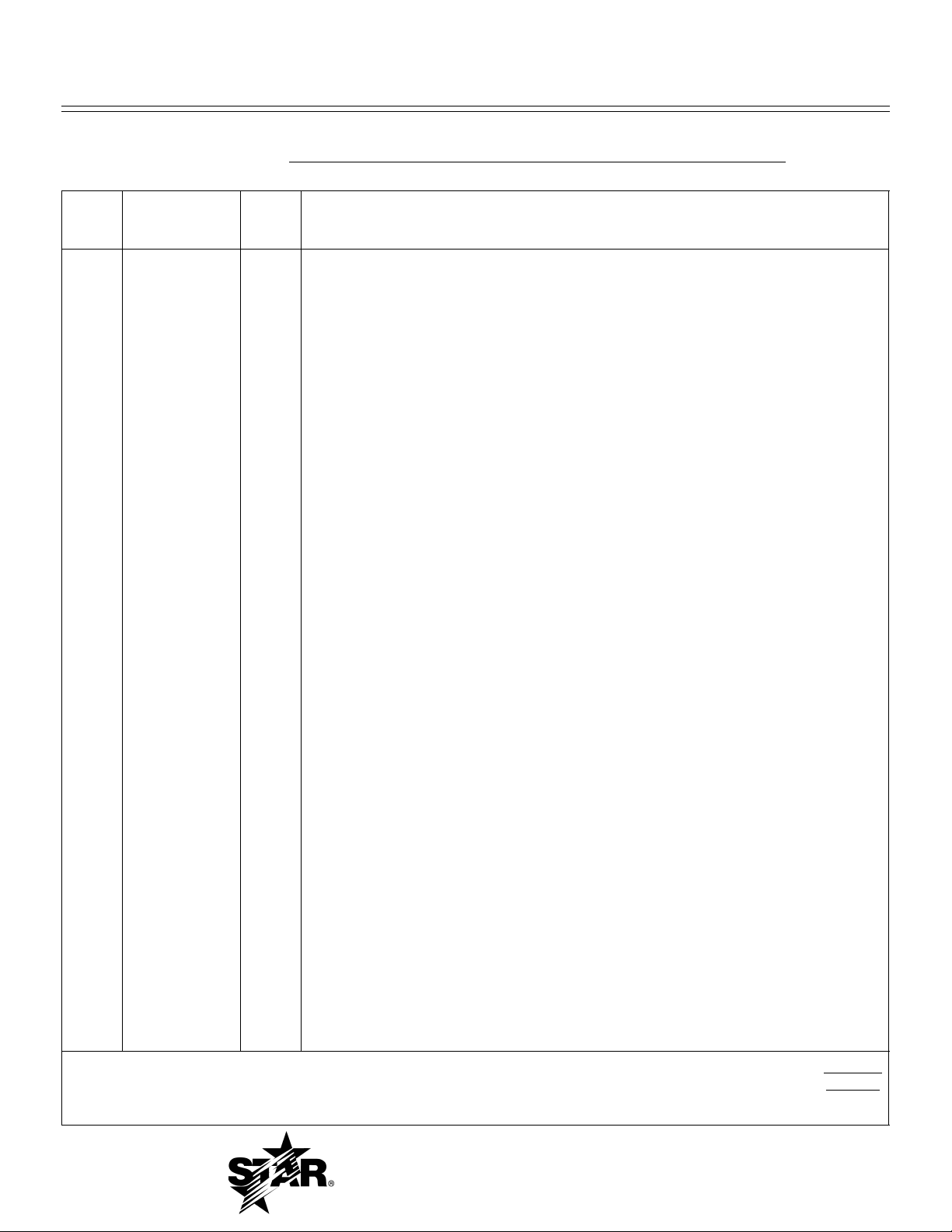
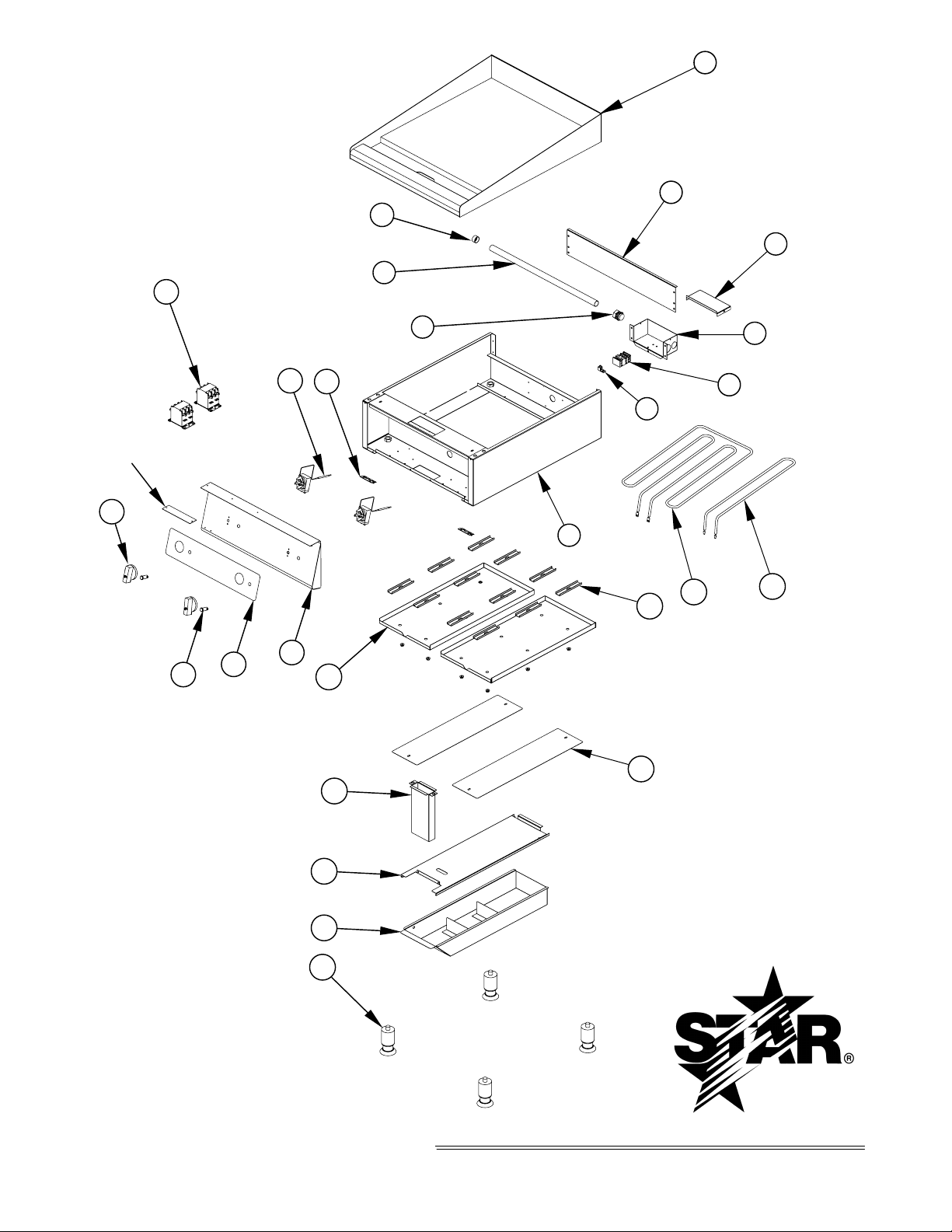
PARTS LIST March 1, 2007, Rev. D
MODEL
724T Ultra-Max Electric Griddles
Key
Number
1 G5-Z8491 1 REAR PANEL 724T
2 G5-824023 1 JUNCTION BOX ASSY. 724T
G5-Z10348 1 ELECTRICAL BOX 724T-230V
3 G5-Z8481 1 JUNCTION BOX COVER 724T
G5-Z10349 1 ELECTRICAL BOX COVER 724T-230V
4 2E-Z8482 1 TERMINAL BLOCK 724T
2E-Z9565 1 TERMINAL BLOCK 5 POS. 724T-230V
5 2E-Z8423 1 GROUND LUG 724T
6 G5-824020 1 GRIDDLE PLATE ASSY. 724T
6 G5-824024 1 GRIDDLE PLATE ASSY. CHROME 724T
7 G5-824021 1 BODY ASSY. 724T
8 2E-Z8358 1 3/4” EMT CONNECTOR 724T
9 2E-Z8361 1 3/4” EMT TUBE - 22 3/4” L. 724T
10 2E-Z8356 1 3/4” PLASTIC BUSHING 724T
11 G5-824022 1 FRONT PANEL ASSY. 724T
12 2M-Z8473 1 FRONT PANEL OVERLAY 724T
13 2P-Z8478 2 HINGE ALL MODELS ALL
14 2E-200529 2 3 POLE CONTACTOR 724T - 230V ONLY
15 2T-Z5958 2 THERMOSTAT 724T
16 2J-Y6690 2 PILOT LIGHT 724T
17 2R-Z8490 2 KNOB 724T
19 2N-Z8484 2 HEATER ELEMENT 4350 W 208V 724T (208V MODELS)
19 2N-Z8485 2 HEATER ELEMENT 4350 W 240V 724T (240V MODELS)
20 2N-Z8487 6 HEATER ELEMENT 1450 W 230V 724T (230V MODELS)
21 G5-Z8489 12 HEATER ELEMENT CLAMP 724T
22 G5-Z8488 2 HEATER ELEMENT SHIELD 724T
23 G5-824012 1 CHUTE ASSY. 724T
24 G5-Z8515 1 DRAWER SLIDE 724T
25 G5-824014 1 GREASE DRAWER ASSY. 724T
26 G5-Z8468 2 BOTTOM PANEL 724T
27 2A-Z4614 4 FOOT ALL MODELS ALL
Part
Number
Number
Per
Unit
Description and Model Designation
1
IMPORTANT: WHEN ORDERING, SPECIFY VOLTAGE OR TYPE GAS DESIRED PAGE
1
INCLUDE MODEL AND SERIAL NUMBER OF
Some items are included for illustrative purposes only and in certain instances may not be available.
Star Manufacturing International, Inc.
10
Page 12
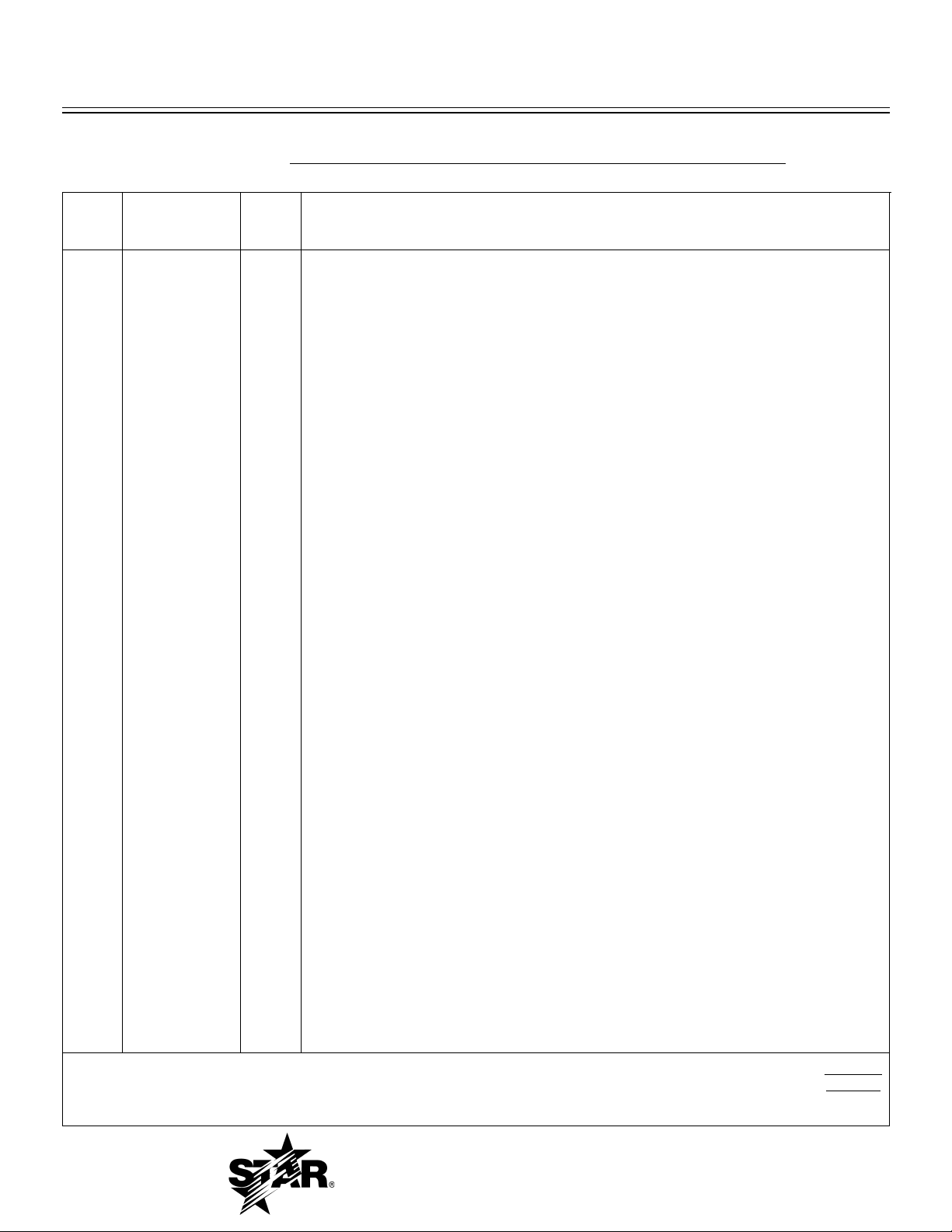
PARTS LIST March 1, 2007, Rev. D
736T Ultra-Max Electric Griddles
MODEL
Number
Key
Number
1 G5-Z8492 1 REAR PANEL 736T
2 G5-824023 1 JUNCTION BOX ASSY. 736T
G5-Z10348 1 ELECTRICAL BOX 736T-230V
3 G5-Z8481 1 JUNCTION BOX COVER 736T
G5-Z10349 1 ELECTRICAL BOX COVER 736T-230V
4 2E-Z8482 1 TERMINAL BLOCK 736T
2E-Z9565 1 TERMINAL BLOCK 5 POS 736T-230V
5 2E-Z8423 1 GROUND LUG 736T
6 G5-836018 1 GRIDDLE PLATE ASSY. 736T
6 G5-836021 1 GRIDDLE PLATE ASSY. CHROME 736T
7 G5-836019 1 BODY ASSY. 736T
8 2E-Z8358 1 3/4” EMT CONNECTOR 736T
9 2E-Z8361 1 3/4” EMT TUBE - 22 3/4” L. 736T
10 2E-Z8356 1 3/4” PLASTIC BUSHING 736T
11 G5-836020 1 FRONT PANEL ASSY. 736T
12 2M-Z8474 1 FRONT PANEL OVERLAY 736T
13 2P-Z8478 2 HINGE ALL MODELS ALL
14 2E-200529 3 3 POLE CONTACTOR 736T - 230V ONLY
15 2T-Z5958 3 THERMOSTAT 736T
16 2J-Y6690 3 PILOT LIGHT 736T
17 2R-Z8490 3 KNOB 736T
19 2N-Z8484 3 HEATER ELEMENT 4350 W 208V 736T (208V MODELS)
19 2N-Z8485 3 HEATER ELEMENT 4350 W 240V 736T (240V MODELS)
20 2N-Z8487 9 HEATER ELEMENT 1450 W 230V 736T (230V MODELS)
21 G5-Z8489 18 HEATER ELEMENT CLAMP 736T
22 G5-Z8488 3 HEATER ELEMENT SHIELD 736T
23 G5-824012 1 CHUTE ASSY. 736T
24 G5-Z8515 1 DRAWER SLIDE 736T
25 G5-824014 1 GREASE DRAWER ASSY. 736T
26 G5-Z8468 1 BOTTOM PANEL 736T
26 G5-Z8469 1 BOTTOM PANEL 736T
27 2A-Z4614 4 FOOT ALL MODELS ALL
Part
Number
Per
Unit
Description and Model Designation
1
IMPORTANT: WHEN ORDERING, SPECIFY VOLTAGE OR TYPE GAS DESIRED PAGE
1
INCLUDE MODEL AND SERIAL NUMBER OF
Some items are included for illustrative purposes only and in certain instances may not be available.
Star Manufacturing International, Inc.
11
Page 13
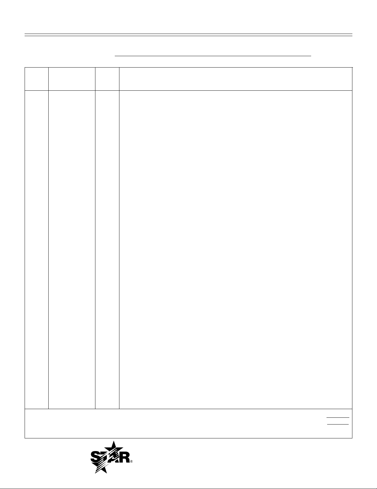
PARTS LIST March 1, 2007, Rev. D
748T Ultra-Max Electric Griddles
MODEL
Number
Key
Number
1 G5-Z8493 1 REAR PANEL 748T
2 G5-824023 1 JUNCTION BOX ASSY. 748T
G5-Z10348 1 ELECTRICAL BOX 748T-230V
3 G5-Z8481 1 JUNCTION BOX COVER 748T
G5-Z10349 1 ELECTRICAL BOX COVER 748T-230V
4 2E-Z8482 1 TERMINAL BLOCK 748T
2E-Z9565 1 TERMINAL BLOCK 5 POS 748T-230V
5 2E-Z8423 1 GROUND LUG 748T
6 G5-848018 1 GRIDDLE PLATE ASSY. 748T
6 G5-848021 1 GRIDDLE PLATE ASSY. CHROME 748T
7 G5-848019 1 BODY ASSY. 748T
8 2E-Z8358 1 3/4” EMT CONNECTOR 748T
9 2E-Z8361 1 3/4” EMT TUBE - 22 3/4” L. 748T
10 2E-Z8356 1 3/4” PLASTIC BUSHING 748T
11 G5-848020 1 FRONT PANEL ASSY. 748T
12 2M-Z8475 1 FRONT PANEL OVERLAY 748T
13 2P-Z8478 2 HINGE ALL MODELS ALL
14 2E-200529 4 3 POLE CONTACTOR 748T - 230V ONLY
15 2T-Z5958 4 THERMOSTAT 748T
16 2J-Y6690 4 PILOT LIGHT 748T
17 2R-Z8490 4 KNOB 748T
19 2N-Z8484 4 HEATER ELEMENT 4350 W 208V 748T (208V MODELS)
19 2N-Z8485 4 HEATER ELEMENT 4350 W 240V 748T (240V MODELS)
20 2N-Z8487 12 HEATER ELEMENT 1450 W 230V 748T (230V MODELS)
21 G5-Z8489 24 HEATER ELEMENT CLAMP 748T
22 G5-Z8488 4 HEATER ELEMENT SHIELD 748T
23 G5-824012 1 CHUTE ASSY. 748T
24 G5-Z8515 1 DRAWER SLIDE 748T
25 G5-824014 1 GREASE DRAWER ASSY. 748T
26 G5-Z8468 1 BOTTOM PANEL 748T
26 G5-Z8470 1 BOTTOM PANEL 748T
27 2A-Z4614 4 FOOT ALL MODELS ALL
Part
Number
Per
Unit
Description and Model Designation
1
IMPORTANT: WHEN ORDERING, SPECIFY VOLTAGE OR TYPE GAS DESIRED PAGE
1
INCLUDE MODEL AND SERIAL NUMBER OF
Some items are included for illustrative purposes only and in certain instances may not be available.
Star Manufacturing International, Inc.
12
Page 14
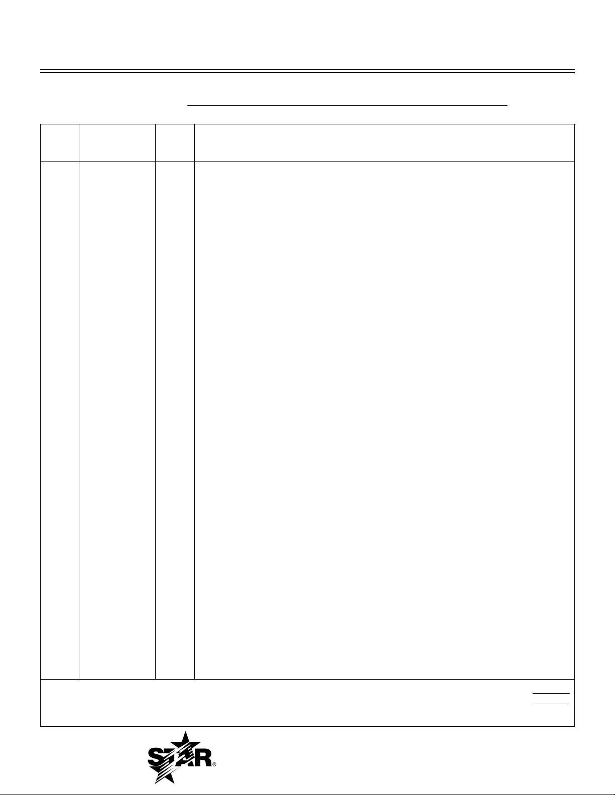
PARTS LIST March 1, 2007, Rev. D
MODEL
760T Ultra-Max Electric Griddles
Number
Key
Number
1 G5-Z8494 1 REAR PANEL 760T
2 G5-824023 2 JUNCTION BOX ASSY. 760T
3 G5-Z8481 2 JUNCTION BOX COVER 760T
4 2E-Z8482 2 TERMINAL BLOCK 760T
5 2E-Z8423 2 GROUND LUG 760T
6 G5-860018 1 GRIDDLE PLATE ASSY. 760T
6 G5-860021 1 GRIDDLE PLATE ASSY. CHROME 760T
7 G5-860019 1 BODY ASSY. 760T
8 2E-Z8358 2 3/4” EMT CONNECTOR 760T
9 2E-Z8361 2 3/4” EMT TUBE - 22 3/4” L. 760T
10 2E-Z8356 2 3/4” PLASTIC BUSHING 760T
11 G5-860020 1 FRONT PANEL ASSY. 760T
12 2M-Z8476 1 FRONT PANEL OVERLAY 760T
13 2P-Z8478 2 HINGE ALL MODELS ALL
15 2T-Z5958 5 THERMOSTAT 760T
16 2J-Y6690 5 PILOT LIGHT 760T
17 2R-Z8490 5 KNOB 760T
19 2N-Z8484 5 HEATER ELEMENT 4350 W 208V 760T (208V MODELS)
19 2N-Z8485 5 HEATER ELEMENT 4350 W 240V 760T (240V MODELS)
21 G5-Z8489 30 HEATER ELEMENT CLAMP 760T
22 G5-Z8488 5 HEATER ELEMENT SHIELD 760T
23 G5-824012 2 CHUTE ASSY. 760T
24 G5-Z8515 2 DRAWER SLIDE 760T
25 G5-824014 2 GREASE DRAWER ASSY. 760T
26 G5-Z8468 2 BOTTOM PANEL 760T
26 G5-Z8471 1 BOTTOM PANEL 760T
27 2A-Z4614 4 FOOT ALL MODELS ALL
Part
Number
Per
Unit
Description and Model Designation
1
IMPORTANT: WHEN ORDERING, SPECIFY VOLTAGE OR TYPE GAS DESIRED PAGE
1
INCLUDE MODEL AND SERIAL NUMBER OF
Some items are included for illustrative purposes only and in certain instances may not be available.
Star Manufacturing International, Inc.
13
Page 15
PARTS LIST March 1, 2007, Rev. D
772T Ultra-Max Electric Griddles
MODEL
Number
Key
Number
1 G5-Z8495 1 REAR PANEL 772T
2 G5-824023 2 JUNCTION BOX ASSY. 772T
3 G5-Z8481 2 JUNCTION BOX COVER 772T
4 2E-Z8482 2 TERMINAL BLOCK 772T
5 2E-Z8423 2 GROUND LUG 772T
6 G5-872018 1 GRIDDLE PLATE ASSY. 772T
6 G5-872021 1 GRIDDLE PLATE ASSY. CHROME 772T
7 G5-872019 1 BODY ASSY. 772T
8 2E-Z8358 2 3/4” EMT CONNECTOR 772T
9 2E-Z8361 2 3/4” EMT TUBE - 22 3/4” L. 772T
10 2E-Z8356 2 3/4” PLASTIC BUSHING 772T
11 G5-872020 1 FRONT PANEL ASSY. 772T
12 2M-Z8477 1 FRONT PANEL OVERLAY 772T
13 2P-Z8478 2 HINGE ALL MODELS ALL
15 2T-Z5958 6 THERMOSTAT 772T
16 2J-Y6690 6 PILOT LIGHT 772T
17 2R-Z8490 6 KNOB 772T
19 2N-Z8484 6 HEATER ELEMENT 4350 W 208V 772T (208V MODELS)
19 2N-Z8485 6 HEATER ELEMENT 4350 W 240V 772T (240V MODELS)
21 G5-Z8489 36 HEATER ELEMENT CLAMP 772T
22 G5-Z8488 6 HEATER ELEMENT SHIELD 772T
23 G5-824012 2 CHUTE ASSY. 772T
24 G5-Z8515 2 DRAWER SLIDE 772T
25 G5-824014 2 GREASE DRAWER ASSY. 772T
26 G5-Z8468 2 BOTTOM PANEL 772T
26 G5-Z8472 1 BOTTOM PANEL 772T
27 2A-Z4614 4 FOOT ALL MODELS ALL
Part
Number
Per
Unit
Description and Model Designation
1
IMPORTANT: WHEN ORDERING, SPECIFY VOLTAGE OR TYPE GAS DESIRED PAGE
1
INCLUDE MODEL AND SERIAL NUMBER OF
Some items are included for illustrative purposes only and in certain instances may not be available.
Star Manufacturing International, Inc.
14
Page 16

STAR MANUFACTURING
10 Sunnen Drive, St. Louis, MO 63143 U.S.A.
(800) 807-9054 (314) 781-2777
Parts & Service (800) 807-9054
www.star-mfg.com
 Loading...