

Page 1
®
®
®
®
®
GAS
GRIDDLE
MODEL
615TD, 615MD
624TD, 624MD, 624MDS 624TSPD, 624TCHSD
636TD, 636MD, 636MDS 636TSPD, 636TCHSD
648TD, 648MD, 648MDS 648TSPD, 648TCHSD
Installation and
Operation
Instructions
2M-Z13220 Rev. - 12/01/09
1
Page 2

2
These symbols are intended to alert the user to the presence of
important operating and maintenance instructions in the manual
accompanying the appliance.
RETAIN THIS MANUAL FOR FUTURE REFERENCE
NOTICE
Using any part other than genuine Star factory supplied parts relieves the
manufacturer of all liability.
Star reserves the right to change specications and product design without
notice. Such revisions do not entitle the buyer to corresponding changes,
improvements, additions or replacements for previously purchased
equipment.
Due to periodic changes in designs, methods, procedures, policies and
regulations, the specications contained in this sheet are subject to change
without notice. While Star International Holdings Inc., Company exercises
good faith efforts to provide information that is accurate, we are not
responsible for errors or omissions in information provided or conclusions
reached as a result of using the specications. By using the information
provided, the user assumes all risks in connection with such use.
MAINTENANCE AND REPAIRS
Contact your local authorized service agent for service or required maintenance.
Please record the model number, serial number, voltage and purchase date in the area below and have it ready when
you call to ensure a faster service.
SAFETY SYMBOL
Model No.
Serial No.
Voltage
Purchase Date
Business 8:00 am to 4:30 p.m. Central Standard Time
Hours:
Telephone: (314) 678-6303
Fax: (314) 781-2714
E-mail Parts@star-mfg.com
Service@star-mfg.com
Warranty@star-mfg.com
Website: www.star-mfg.com
Service Help Desk
Authorized Service Agent Listing
Reference the listing provided with the unit
or
for an updated listing go to:
Website: www.star-mfg.com
E-mail Service@star-mfg.com
Mailing Address: Star International Holdings Inc., Company
10 Sunnen Drive
St. Louis, MO 63143
U.S.A
2
Page 3

SPECIFICATIONS
615MD, 615MD-LP
Type: Manual Control
1 Control, 20,000 BTU, 304 sq. in. (1961 sq. cm) Grid Area, 3/4" (1.9 cm) Plate Thickness
Approximate Weight: Installed - 83 Lb (37.6 kg), Shipping - 90 Lb, (40.8 kg)
Dimensions: 15" - Width, 27-3/4" - Depth, 15 1/2" - Height (38.1 cm - Width, 70.5 cm - Depth, 39.4 cm- Height)
624MD, 624MD-LP, 624MDS
Type: Manual Control
2 Controls, 40,000 BTU, 498 sq. in. (3213 sq. cm) Grid Area, 3/4" (1.9 cm) Plate Thickness
Approximate Weight: Installed - 165 Lb (74.8 kg), Shipping - 175 Lb, (79.4 kg)
Dimensions: 24" - Width, 27-3/4" - Depth, 15 1/2"- Height (61 cm - Width, 70.5 cm - Depth, 39.4 cm- Height)
636MD, 636MD-LP, 636MDS
Type: Manual Control
3 Controls, 60,000 BTU, 747 sq. in. (4820 sq. cm) Grid Area, 3/4" (1.9 cm) Plate Thickness
Approximate Weight: Installed - 247 Lb (112 kg), Shipping - 262 Lb, (118.8 kg)
Dimensions: 36" - Width, 27-3/4" - Depth, 15 1/2" - Height (91.4 cm - Width, 70.5 cm - Depth, 39.4 cm - Height)
648MD, 648MD-LP, 648MDS
Type: Manual Control
4 Controls, 80,000 BTU, 996 sq. in. (6426 sq. cm) Grid Area, 3/4" (1.9 cm) Plate Thickness
Approximate Weight: Installed - 330 Lb (144.7 kg), Shipping - 350 Lb, (158.8 kg)
Dimensions: 48" - Width, 27-3/4" - Depth, 15 1/2" - Height (122 cm - Width, 70.5 cm - Depth, 39.4 cm - Height)
615TD, 615TD-LP
Type: Thermostat Control
1 Control, 20,000 BTU, 304 sq. in. (1961 sq. cm) Grid Area, 3/4" (1.9 cm) Plate Thickness
Approximate Weight: Installed - 83 Lb (37.6 kg), Shipping - 90 Lb, (40.8 kg)
Dimensions: 15" - Width, 27-3/4" - Depth, 15 1/2"- Height (38.1 cm - Width, 70.5 cm - Depth, 39.4 cm- Height)
624TD, 624TD-LP
Type: Thermostat Control
2 Controls, 40,000 BTU, 498 sq. in. (3213 sq. cm) Grid Area, 3/4" (1.9 cm) Plate Thickness
Approximate Weight: Installed - 165 Lb (74.8 kg), Shipping - 175 Lb, (79.4 kg)
Dimensions: 24" - Width, 27-3/4" - Depth, 15 1/2"- Height (61 cm - Width, 70.5 cm - Depth, 39.4 cm- Height)
636TD, 636TD-LP
Type: Thermostat Control
3 Controls, 60,000 BTU, 747 sq. in. (4820 sq. cm) Grid Area, 3/4" (1.9 cm) Plate Thickness
Approximate Weight: Installed - 247 Lb (112 kg), Shipping - 262 Lb, (118.8 kg)
Dimensions: 36" - Width, 27-3/4" - Depth, 15 1/2"- Height (91.4 cm - Width, 70.5 cm - Depth, 39.4 cm - Height)
648TD, 648TD-LP
Type: Thermostat Control
4 Controls, 80,000 BTU, 996 sq. in. (6426 sq. cm) Grid Area, 3/4" (1.9 cm) Plate Thickness
Approximate Weight: Installed - 330 Lb (144.7 kg), Shipping - 350 Lb, (158.8 kg)
Dimensions: 48" - Width, 27-3/4" - Depth, 15 1/2" - Height (122 cm - Width, 70.5 cm - Depth, 39.4 cm - Height)
624TSPD
Type: Thermostat & Safety Pilot Control
2 Controls, 56,6000 BTU, 498 sq. in. (3213 sq. cm) Grid Area, 3/4" (1.9 cm) Plate Thickness
Approximate Weight: Installed - 165 Lb (74.8 kg), Shipping - 175 Lb, (79.4 kg)
Dimensions: 24" - Width, 27-3/4" - Depth, 15 1/2"- Height (61 cm - Width, 70.5 cm - Depth, 39.4 cm - Height)
636TSPD
Type: Thermostat & Safety Pilot Control
3 Controls, 84,900 BTU, 747 sq. in. (4820 sq. cm) Grid Area, 3/4" (1.9 cm) Plate Thickness
Approximate Weight: Installed - 247 Lb (112 kg), Shipping - 262 Lb, (118.8 kg)
Dimensions: 36" - Width, 27-3/4" - Depth, 15 1/2"- Height (91.4 cm - Width, 70.5 cm - Depth, 39.4 cm - Height)
648TSPD
Type: Thermostat & Safety Pilot Control
4 Controls, 113,200 BTU, 996 sq. in. (6426 sq. cm) Grid Area, 3/4" (1.9 cm) Plate Thickness
Approximate Weight: Installed - 330 Lb (144.7 kg), Shipping - 350 Lb, (158.8 kg)
Dimensions: 48" - Width, 27-3/4" - Depth, 15 1/2"- Height (122 cm - Width, 70.5 cm - Depth, 39.4 cm - Height)
3
Page 4

SPECIFICATIONS (CHROME-MAX GAS GRIDDLES)
624TCHSD
Type: Thermostat & Safety Pilot Control with Chrome Plate
2 Controls, 56,6000 BTU, 498 sq. in. (3213 sq. cm) Grid Area, 3/4" (1.9 cm) Plate Thickness
Approximate Weight: Installed - 165 Lb (74.8 kg), Shipping - 175 Lb, (79.4 kg)
Dimensions: 24" - Width, 27-3/4" - Depth, 15 1/2" - Height (61 cm - Width, 70.5 cm - Depth, 39.4 cm - Height)
636TCHSD
Type: Thermostat & Safety Pilot Control with Chrome Plate
3 Controls, 84,900 BTU, 747 sq. in. (4820 sq. cm) Grid Area, 3/4" (1.9 cm) Plate Thickness
Approximate Weight: Installed - 247 Lb (112 kg), Shipping - 262 Lb, (118.8 kg)
Dimensions: 36" - Width, 27-3/4" - Depth, 15 1/2"- Height (91.4 cm - Width, 70.5 cm - Depth, 39.4 cm - Height)
648TCHSD
Type: Thermostat & Safety Pilot Control with Chrome Plate
4 Controls, 113,200 BTU, 996 sq. in. (6426 sq. cm) Grid Area, 3/4" (1.9 cm) Plate Thickness
Approximate Weight: Installed - 330 Lb (144.7 kg), Shipping - 350 Lb, (158.8 kg)
Dimensions: 48" - Width, 27-3/4" - Depth, 15 1/2" - Height (122 cm - Width, 70.5 cm - Depth, 39.4 cm - Height)
Units operate on Natural and Propane Gas
4
Page 5
CAUTION
CAUTION
GENERAL INSTALLATION DATA
This equipment is designed and sold for commercial use only by personnel trained and experienced
in its operation and is not sold for consumer use in and around the home nor for use directly by the
general public in food service locations.
The Star-Max™ model griddles are equipped for use with the types of gas specied on the
nameplate.
All units are shipped from the factory for use with natural gas. The unit can easily be converted for
use on propane gas: See propane gas.
-IMPORTANT-
The installation of the Appliance should conform to the NATIONAL FUEL GAS
CODE "ANSI Z223.1 - LATEST EDITION" AND ALL LOCAL GAS COMPANY
RULES AND REGULATIONS.
IN CANADA INSTALLATION SHALL BE IN ACCORDANCE WITH THE
CURRENT CAN/CGA-B149.1 NATURAL GAS INSTALLATION CODE OR
CAN/CGA-B149.2 PROPANE INSTALLATION CODE AND LOCAL CODES
WHERE APPLICABLE.
Improper installation, adjustment, alteration, service or maintenance can cause property
damage, injury or death. Read the installation, operating and maintenance instructions
thoroughly before installing or servicing the equipment.
CAUTION
CAUTION
For your safety, do not store or use gasoline or other ammable vapors and
liquids in the vicinity of this or any other appliance. Keep the appliance area
clear and free from combustibles.
This appliance, its pressure regulator and its individual shutoff valve must be disconnected from the
gas supply piping system during any pressure testing of that system at test pressures in excess of 1/2
PSIG (3.45KPA).
This appliance and its pressure regulator must be isolated from the gas supply piping system by
closing its individual manual shutoff valve during any pressure testing of the gas supply piping system
at test pressures equal to or less than 1/2 PSIG (3.45KPA). For your protection, we recommend a
qualied installing agency install this appliance. They should be familiar with gas installations and
your local gas requirements. In any case, your gas company should be called to approve the nal
installation. In addition, there should be posted, in a prominent location, detailed instructions to be
followed in the event the operator smells gas. Obtain the instructions from the local gas supplier.
For your safety, if you smell gas -
1. Do not touch electrical switches.
2. Extinguish any open ame.
3. Immediately call your gas company.
KEEP THE APPLIANCE AREA FREE AND CLEAR FROM COMBUSTIBLES.
CLEARANCE
For use on non-combustible countertops only.
Combustible and non-combustible material must be at least 48" (120cm) from the top of the appliance
and 6" (150mm) from the sides and back. Adequate clearance should also be provided for proper
operation and servicing.
AIR SUPPLY
Make certain not to obstruct the ow of combustion and ventilation air. Provisions for adequate air
supply must be furnished. The legs supplied with the unit must be installed. Make certain that air
intake openings in the bottom of the appliance are not obstructed. They are essential for proper
combustion and operation of the appliance.
5
Page 6

CAUTION
EXHAUST CANOPY
It is essential that facilities be provided over the griddle to carry off fumes and gases. However, the
unit should not be directly connected to a ue or stack.
LEVELING UNIT
This griddle is supplied with (4) feet which must be screwed into the legs attached to the body. Level
unit by adjusting the (4) feet which have an adjustment of 1-3/4" (43.75mm) for accurate and perfect
lineup with other units.
DO NOT INSTALL WITHOUT ATTACHING FEET - DO NOT REMOVE FEET.
GAS PIPING
Gas piping shall be of such size and so installed as to provide a supply of gas sufcient to meet
the full gas input of the appliance. If the appliance is to be connected to existing piping, it shall be
checked to determine if it has adequate capacity. Joint compound shall be used sparingly and only
on the male threads of the pipe joints. Such compounds shall be resistant to the action of LP gases.
WARNING: Any loose dirt or metal particles which are allowed to enter the gas lines on this appliance
will damage the valve and affect its operation. When installing this appliance, all pipe and ttings must
be free from loose dirt.
GAS PRESSURE REGULATOR
A convertible pressure regulator is provided with each griddle. It should be connected to the inlet pipe
at the rear of the unit. The gas supply line is then connected to it. It is shipped set for 6" (15.24cm)
water column manifold pressure for use with natural gas.
MANUAL SHUT-OFF VALVE
A manual shut-off valve should be installed upstream from the union and within 6 feet (1.829m) of this
appliance.
GAS CONVERSION
This griddle is equipped with xed orice hoods and is shipped from the factory for use on either
natural or LP gas. To convert to propane gas, install the burner orice hoods, located in the grease
drawer, (NAT orces are not included) as follows:
1. Remove front panel by removing screws located on the front and the bottom.
2. Remove the burner(s) from the orice hood(s). This is accomplished by removing the burner
mounting screw(s) and sliding the burner(s) off the hood(s).
3. Remove natural gas orice hood(s) and install the propane hood(s) furnished.
4. Reinstall burner(s).
Note: MD and TD series units use a #47 drill orice for natural gas and a #55 drill orice
for propane. TCHSD and TSPD series units (w/safety pilots) use a #41 drill orice for
natural gas and a #52 drill orice for propane gas.
5. Reinstall front panel.
6. Remove the slotted, or hex-threaded, plug from the pressure regulator. Invert the plug and reinstall. The letters "LP or NAT" should now be visible on the plug. LP units the regulator is now
set for 10" (25.4cm) water column, and NAT units the regulator is now set for 6" (15.24cm) water
column.
7. For LP Gas, set manifold pressure to 10" (25.4cm) water column. A 1/8" pipe plug on the supply
pipe can be removed for attaching a pressure gauge.
CONNECTING GAS SUPPLY LINE
The gas inlet of the griddle is sealed at the factory to prevent entry of dirt. Do not remove this seal
until the actual connection is made to the gas supply line.
CHECKING FOR GAS LEAKS
Soap and water solution or other material acceptable for the purpose shall be used in locating gas
leakage. Matches, candle ame, or other sources of ignition shall not be used for this purpose.
Check entire piping system for leaks.
6
Page 7

CAUTION
LIGHTING INSTRUCTIONS
When griddle is rst lit, it will smoke until the preservation oils and impurities are burned off.
1. Turn off main valve to unit and wait 5 minutes to clear gas.
2. Turn off all knobs and pilot valves.
3. Turn on main valve and light all pilots.
4. Turn burner knobs to desired setting.
5. To turn burners off, turn knobs off.
NOTE: The griddles are equipped with standing pilots and should be lit immediately after
the gas is turned on.
Pilot ames can be lit and observed through the front panel view ports. However, best access for
lighting the pilot is from the bottom of the unit just behind the center wall.
LIGHTING INSTRUCTIONS (TCHSD and TSPD SERIES)
1. Turn the control knobs to the "OFF" position.
If the gas valves have been on and gas has escaped through the burners, turn the burners
"OFF" and wait 5 minutes to clear the gas.
2. Turn the control knob to the "PILOT" position, depress and hold the knob while lighting the pilot.
Hold the knob in for 60 seconds or until the pilot stays lit. (Repeat for all burner sections.)
3. Depress and turn the control knob to the desired temperature.
4. To turn the burners off turn the knob to the "PILOT" position.
5. To turn off all gas turn the knob to the "OFF" position. The pilots must be relit to resume cooking
settings.
PILOT LIGHT REGULATION
Adjust pilot light ames as small as possible, but high enough to light burner immediately when burner
valve is turned on high.
ADJUSTING SAFETY PILOTS (SERIES TCHSD and TSPD ONLY)
A manual pilot valve is provided on the left side of the control to adjust the pilot ame. Adjust the pilot
ame so that it is approximately 3/8 to 1/2" tall and a uniform cone shape.
BURNER ADJUSTMENT (MODELS MD and MDS ONLY)
1. Remove the front panel.
2. Turn burner valve knob to "HI" position.
3. Close the air shutter on the front of the burner to give a soft blue ame having luminous tips and
open to a point where the yellow tips disappear and a hard blue ame is obtained. Repeat for all
burners.
BURNER ADJUSTMENT (MODELS TD, TCHSD and TSPD ONLY)
1. Remove the front panel.
2. Push dial in and set thermostat of one burner to 450°F (229.9°C).
3. Close the air shutter on the front of the burner to give a soft blue ame having luminous tips and
open to a point where the yellow tips disappear and a hard blue ame is obtained. Repeat for all
burners.
BURNER OPERATION (MODELS MD and MDS ONLY)
To ignite burners, turn burner valve knob to "HI" position. Each burner is controlled by an individual
high-low, on-off valve. An innite number of temperatures may be obtained by turning the burner valve
knob to any position between high and low. For overnight shutdown, turn the valves to the "OFF"
position.
7
Page 8

CAUTION
SEASONING THE GRIDDLE HEATING SURFACE
(NON-CHROMIUM SURFACES)
Clean the griddle surface thoroughly. After the griddle has been thoroughly cleaned, it should be
seasoned to prevent food from sticking. Before using, and after each thorough scouring, season the
griddle heating surface in the following manner:
1. Turn the temperature control dial to 350°F (174.9°C).
2. Using a clean cloth, not a spatula, spread a thin lm of cooking oil over the griddle cooking surface.
This lm should remain on the hot griddle surface 1/2 hour.
3. Remove excess oil and wipe clean.
4. Apply another lm of cooking oil over the hot cooking area for another 1/2 hour and again remove
excess oil and wipe clean. The griddle surface should now be ready for use.
Even with careful seasoning food may, to some extent, stick to the griddle cooking
surface until griddle plate is "broken in."
COOKING (MODELS TD, TCHSD and TSPD ONLY)
Set the thermostat dial knob to the temperature desired. After a short preheating period, the
thermostat will automatically maintain the selected temperature.
GREASE PAN
A grease pan is located at the front and can be removed for cleaning from the front. This pan should
be checked and emptied when necessary.
EXERCISE EXTREME CARE IN HANDLING THE GREASE PAN CONTAINING HOT
GREASE.
GRIDDLE CARE (NON-CHROMIUM AREAS)
It takes very little time and effort to keep the griddle attractive and performing at top efciency.
If grease is permitted to accumulate, it will form a gummy cake and then carbonize into a hard
substance which is extremely difcult to remove. To prevent this condition, the following suggestions
for cleanliness should be followed:
1. After each use, scrape the griddle with a scraper or exible spatula to remove excess grease and
food. A waste drawer is provided for the scrapings. If there is an accumulation of burned on grease
and food, the griddle should be thoroughly scoured and reseasoned. Use pumice or griddle stone
while the griddle is warm. Do not use steel wool because of the danger of steel slivers getting into
the food.
2. Daily-use a clean cloth and good non-abrasive cleaner to clean the stainless steel body of the
griddle. Wipe the polished front with a soft cloth.
3. At least once a day remove the waste drawer and wash in the same way as an ordinary cooking
utensil. The drawer is removed by pulling forward, up and out.
GRIDDLE CARE (CHROMIUM AREAS)
It takes very little time and effort to keep this Chromium griddle surface sparkling clean and
performing at top efciency. DO NOT allow grease to accumulate as it will carbonize, becoming
difcult to remove. To prevent this condition the following cleaning suggestions should be followed.
1. Remove excess oil and food regularly with a 4" (100mm) wide Razor Sharp type scraper and wipe
surface with a damp cloth.
2. Following the scraping, a damp cloth and a non-silicated, non-abrasive, non-chlorinated cleaner
such as Bon-Ami may be used to wipe surface clean, followed by wiping with clean wet cloth.
3. Follow steps 2 and 3 from above section.
8
Page 9

CAUTION
CAUTION
1. Never use pumice, griddle stones, or abrasives on the surface.
2. Never strike griddle surface with sharp instrument or spatula edge.
3. Never use steel wool.
4. Never use commercial liquid grill cleaner on the griddle surface.
5. Abusing surface voids the warranty.
CHROME-MAX™ GRIDDLE SURFACE LIMITED WARRANTY EXCLUSIONS
Your Chrome-Max griddle has been designed to give you many years of cooking reliability and
requires minimum maintenance to keep the chrome surface in its original condition. All ChromeMax griddle surfaces are warranted for a period of 5 years against manufacturing defects to the
original owner from the date of installation. This limited warranty is void if it is determined by Star
Manufacturing International Incorporated or one of its' authorized representatives that the chrome
surface has been misused or abused or subjected to the following situations:
1. Improperly installed.
2. By-pass adjustments not set properly on gas units allowing the appliance to overheat and discolor
the chrome surface. (See by-pass adjustment in instruction manual supplied with unit.)
3. The misuse of any instrument or tool which scratches or makes indentations in the surface which
could cause the surface to peel, ake, or chip off.
4. The use of any chemical or abrasive cleaning solution, griddle brick, stone, screen or other cleaning
products which could damage and affect the performance of the chrome surface.
5. The neglect of daily routine maintenance to the chromium surface.
9
Page 10

2M-4497-2 10/2010
The foregoing warranty is in lieu of any and all other warranties expressed or implied and constitutes the entire warranty.
FOR ASSISTANCE
Should you need any assistance regarding the Operation or Maintenance of any Star equipment; write, phone, fax or email our Service Department.
In all correspondence mention the Model number and the Serial number of your unit, and the voltage or type of gas you are using.
ALL:
* Pop-Up Toasters
* Butter Dispensers
* Pretzel Merchandisers
(Model 16PD-A Only)
* Pastry Display Cabinets
* Nacho Chip Merchandisers
* Accessories of any kind
* Sneeze Guards
* Pizza Ovens
(Model PO12 Only)
* Heat Lamps
* Pumps-Manual
Visit our Website at: www.star-mfg.com Email: service@star-mfg.com
THOROUGHLY INSPECT YOUR UNIT ON ARRIVAL
This unit has been tested for proper operation before leaving our plant to insure delivery of your unit in perfect condition. However, there are instances in
which the unit may be damaged in transit. In the event you discover any type of damage to your product upon receipt, you must immediately contact the
transportation company who delivered the item to you and initiate your claim with same. If this procedure is not followed, it may affect the warranty status of
the unit.
LIMITED EQUIPMENT WARRANTY
All workmanship and material in Star products have a one (1) year limited warranty on parts & labor in the United States and Canada. Such warranty is limited
to the original purchaser only and shall be effective from the date the equipment is placed in service. Star's obligation under this warranty is limited to the repair
of defects without charge, by the factory authorized service agency or one of its sub-agencies. Models that are considered portable (see below) should be taken
to the closest Star service agency, transportation prepaid.
> Star will not assume any responsibility for loss of revenue.
> On all shipments outside the United States and Canada, see International Warranty.
* The warranty period for the JetStar six (6) ounce & Super JetStar eight (8) ounce series popcorn machines is two (2) years.
* The warranty period for the Chrome-Max Griddles is ve (5) years on the griddle surface. See detailed warranty provided with unit.
* The warranty period for Teon/Dura-Tec coatings is one year under normal use and reasonable care. This warranty does not apply if damage occurs to
Teon/Dura-Tec coatings from improper cleaning, maintenance, use of metallic utensils, or abrasive cleaners, abrasive pads, product identiers and
point-of-sale attachments, or any other non-food object tha comes in continuous contact with the roller coating. This warranty does not apply to the
“non-stick” properties of such materials.
> This warranty does not apply to "Special Products" but to regular catalog items only. Star's warranty on "Special Products" is six (6) months on parts
and ninety (90) days on labor.
> This warranty does not apply to any item that is disassembled or tampered with for any purpose other than repair by a Star Authorized Service Center or
the Service Center's sub-agency.
> This warranty does not apply if damage occurs from improper installation, misuse, wrong voltage, wrong gas or operated contrary to the Installation and
Operating instructions.
> This warranty is not valid on Conveyor Ovens unless a "start-up/check-out" has been performed by a Factory Authorized Technician.
PARTS WARRANTY
Parts that are sold to repair out of warranty equipment are warranted for ninety (90) days. The part only is warranted. Labor to replace the part is chargeable to
the customer.
SERVICES NOT COVERED BY WARRANTY
PORTABLE EQUIPMENT
Star will not honor service bills that include travel time and mileage charges for servicing any products considered "Portable" including items listed below.
These products should be taken to the Service Agency for repair:
1. Travel time and mileage rendered beyond the 50 mile radius limit
2. Mileage and travel time on portable equipment (see below)
3. Labor to replace such items that can be replaced easily during a daily cleaning
routine, ie; removable kettles on fryers, knobs, grease drawers on griddles, etc.
4. Installation of equipment
5. Damages due to improper installation
6. Damages from abuse or misuse
7. Operated contrary to the Operating and Installation Instructions
8. Cleaning of equipment
9. Seasoning of griddle plates
10. Voltage conversions
11. Gas conversions
12. Pilot light adjustment
13. Miscellaneous adjustments
14. Thermostat calibration and by-pass adjustment
15. Resetting of circuit breakers or safety controls or reset buttons
16. Replacement of bulbs
17. Replacement of fuses
18. Repair of damage created during transit, delivery, &
installation OR created by acts of God
* The Model 510FD Fryer.
* The Model 526TOA Toaster Oven.
* The Model J4R, 4 oz. Popcorn Machine.
* The Model 518CMA & 526CMA Cheese Melter.
* The Model 12MC & 15MC & 18MCP Hot Food Merchandisers.
* The Model 12NCPW & 15NCPW Nacho Chip/Popcorn Warmer.
* All Hot Dog Equipment except Roller Grills & Drawer Bun Warmers.
* All Nacho Cheese Warmers except Model 11WLA Series Nacho Cheese Warmer.
* All Condiment Dispensers except the Model HPD & SPD Series Dispenser.
* All Specialty Food Warmers except Model 130R, 11RW Series, and 11WSA Series.
* All QCS/RCS Series Toasters except Model QCS3 & RCS3 Series.
* All Fast Steamer Models except Direct Connect Series.
2M-Z13220 Star-Max Gas Griddles
10
Page 11

2
3
Max
Star
1
4
5
6
7
8
9
10
11
12
13
14
15
17
18
19
21
22
23
16
40
STAR MANUFACTURING INTERNATIONAL, INC.
MODEL 624MD,624TD, 624TSPD, 624TCHSD
SK1980 REV A 05-9-03
2M-Z13220 Star-Max Gas Griddles
11
Page 12

STAR MANUFACTURING INTERNATIONAL, INC.
MODEL 624MD,624TD, 624TSPD, 624TCHSD
SK1988 Rev. B 9-3-2010
26
27
28
29
30
24
20
Manual Control
29
28
30
31
32
33
34
35
36
37
25
29
27
33
37
38
39
25
28
Thermostat Control
12
2M-Z13220 Star-Max Gas Griddles
Page 13

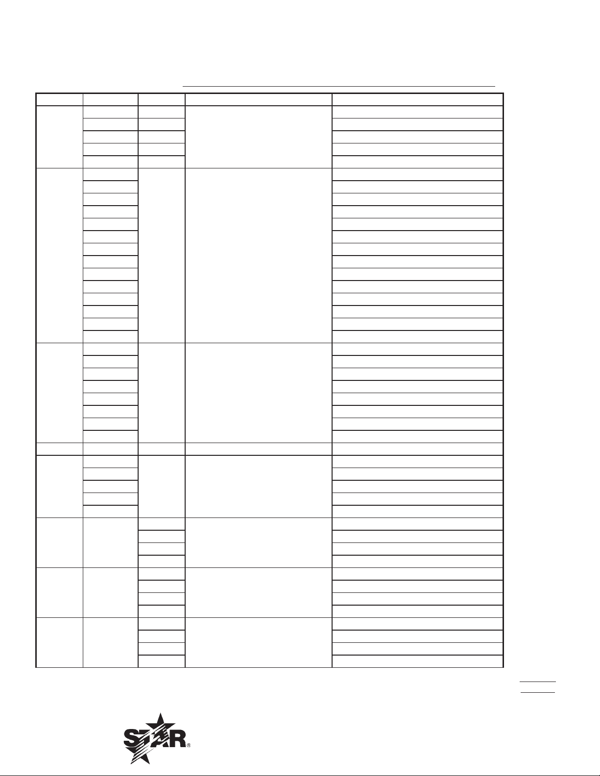
PARTS LIST October 12, 2011, Rev -
615-648TD, 615-648MD, 624-648MDS, 624-648TSPD, 624-648TCHSD
15", 24", 36" and 48" Star-Max/Chrome-Max Gas Griddles
MODEL
Fig No Part No Qty Description Application
G3-615305
G3-624305 624MD
G3-624313 DIVIDED PLATE ASSEMBLY 624MD-DIV
G3-636305
G3-648305 648MD
G3-648313 648TD-TFR
1
2
3 G5-Z4817 1 FLUE DIVIDER ALL 636, 648
4 G3-Z5945 2 SIDE PANEL ALL
5 G3-624302 1 SIDE LINER ASSEMBLY LEFT ALL
6
7 G3-624303 1 SIDE LINER ASSEMBLY RIGHT ALL
8
9 2F-Z5949 1/2/3/4 BURNER ALL 615 / 624 / 636 / 648
10
11 2A-Z5942 4 FOOT ALL
12 G3-Z6036 2 DRAWER SLIDE ALL
13 G3-Y7046 1 GREASE DRAWER ALL
2M-Z13220 Star-Max Gas Griddles
14
15 G3-Z5946 1/2/3/4 BURNER COVER ALL 615 / 624 / 636 / 648
G3-648314 648TD-TFL
G3-615310 615TD
G3-624310 624TD, 624TSPD
G3-636310 636TD, 636TSPD
G3-648310 648TD, 648TSPD
G3-624311 624TCHSD
G3-636311 636TCHSD
G3-648311 648TCHSD
G3-Z5906
G3-Z5916 624MD, 624TD, 624TSPD, 624TCHSD
G3-Z5926 636MD, 636TD, 636TSPD, 636TCHSD
G3-Z5936 648MD, 648TD, 648TSPD, 648TCHSD
G3-Z5951
G3-Z5953 624MD, 624TD, 624TSPD, 624TCHSD
G3-Z5955 636MD, 636TD, 636TSPD, 636TCHSD
G3-Z5957 648MD, 648TD, 648TSPD, 648TCHSD
G3-Z5909
G3-Z5919 624MD, 624TD, 624TSPD, 624TCHSD
G3-Z5929 636MD, 636TD, 636TSPD, 636TCHSD
G3-Z5939 648MD, 648TD, 648TSPD, 648TCHSD
G3-624304
G3-615304 ALL 615
G3-Z5905
G3-Z5915 624MD, 624TD, 624TSPD, 624TCHSD
G3-Z5925 636MD, 636TD, 636TSPD, 636TCHSD
G3-Z5935 648MD, 648TD, 648TSPD, 648TCHSD
GRIDDLE PLATE ASSEMBLY
1
GRIDDLE PLATE ASSEMBLY
1 FLUE
REAR PANEL
1
1 BOTTOM
1 CHUTE ASSEMBLY
CENTER WALL
1
615MD
636MD
615MD, 615TD
615MD, 615TD
615MD,615TD
ALL 624, 636, 648
615MD, 615TD
IMPORTANT: WHEN ORDERING, SPECIFY VOLTAGE OR TYPE GAS DESIRED PAGE 1
INCLUDE MODEL AND SERIAL NUMBER OF 3
Some items are included for illustrative purposes only and in certain instances may not be available.
Star International Holdings, Inc. Company
13
Page 14
PARTS LIST October 12, 2011, Rev -
615-648TD, 615-648MD, 624-648MDS, 624-648TSPD, 624-648TCHSD
15", 24", 36" and 48" Star-Max/Chrome-Max Gas Griddles
MODEL
Fig No Part No Qty Description Application
2R-Z0934 1/2/3/4
2R-Z1273 1/2/3/4 615TD / 624TD / 636TD / 648TD
16
17
18
19 VARIOUS 1 NAMEPLATE ALL
20
21 G3-GD0036
22 G3-Y9531
23 G3-Z4398
IMPORTANT: WHEN ORDERING, SPECIFY VOLTAGE OR TYPE GAS DESIRED PAGE 2
INCLUDE MODEL AND SERIAL NUMBER OF 3
Some items are included for illustrative purposes only and in certain instances may not be available.
2R-Z0934 2/3/4 624TSPD / 636TSPD / 648TSPD
2R-Z0934 2/3/4 624TCHSD / 636TCHSD / 648TCHSD
2R-Z6184 2/3/4 624MDS / 636MDS / 648MDS
2M-Z5982
2M-Z5983 615TD
2M-Z5984 624MD
2M-Z5985 624TD
2M-Z5986 636MD
2M-Z5987 636TD
2M-Z5988 648MD
2M-Z5989 648TD
2M-Z5990 624TSPD, 624TCHSD
2M-Z5991 636TSPD, 636TCHSD
2M-Z5992 648TSPD, 648TCHSD
2M-Z6545 624MDS
2M-Z6546 636MDS
2M-Z6547 648MDS
G3-Z5974
G3-Z5975 615TD
G3-Z5976 624MD
G3-Z5977 624TD, 624TSPD, 624TCHSD
G3-Z5978 636MD
G3-Z5979 636TD, 636TSPD, 636TCHSD
G3-Z5980 648MD
G3-Z5981 648TD, 648TSPD, 648TCHSD
2K-Z5960
2K-Z5961 615TD
2K-Z5962 624MD
2K-Z5964 636MD
2K-Z5966 648MD
KNOB
1 GRAPHIC PANEL
1
FRONT PANEL
1 MANIFOLD
1
2 624TD, 624TSPD, 624TCHSD
TUBE-WASHER ASSY.
3 636TD, 636TSPD, 636TCHSD
4 648TD, 648TSPD, 648TCHSD
1
2
INSULATOR
3 636TD, 636TSPD, 636TCHSD
4 648TD, 648TSPD, 648TCHSD
1
2 624TD, 624TSPD, 624TCHSD
BULB CLAMP
3 636TD, 636TSPD, 636TCHSD
4 648TD, 648TSPD, 648TCHSD
615MD / 624MD / 636MD / 648MD
615MD
615MD
615MD
615TD
615TD
624TD, 624TSPD, 624TCHSD
615TD
2M-Z13220 Star-Max Gas Griddles
Star International Holdings, Inc. Company
14
Page 15

PARTS LIST October 12, 2011, Rev -
615-648TD, 615-648MD, 624-648MDS, 624-648TSPD, 624-648TCHSD
15", 24", 36" and 48" Star-Max/Chrome-Max Gas Griddles
MODEL
Fig No Part No Qty Description Application
24 2J-Z0792 1
2K-Z5960
2K-Z5961 615TD
2K-Z5962
25
26 2V-Y8832 1/2/3/4 MANUAL VALVE 615MD / 624MD / 636MD / 648MD
27 2V-Z6647 1/2/3/4 PILOT BURNER
28 2V-6671 1/2/3/4 PILOT VALVE ALL 615 / 624 / 636 / 648
29 2P-1453
30
31 2J-Z5959 2/3/4 COMBINATION CONTROL
32 2K-Z5968 2/3/4 FITTING 1/4 MPT X 3/8 CC
33 2K-Z4921
34 2K-Z6081 2/3/4 PILOT TUBE
35 2J-Z0804 2/3/4 THERMOCOUPLE-PILOT
36 G3-Z6124 2/3/4 PILOT BRACKET
2M-Z13220 Star-Max Gas Griddles
37 2A-9369
38 2K-Y7111 1/2/3/4 ELBOW 1/4 MBT X 3/8 CC 615TD / 624TD / 636TD / 648TD
39
40 2C-8823 Various
IMPORTANT: WHEN ORDERING, SPECIFY VOLTAGE OR TYPE GAS DESIRED PAGE 3
INCLUDE MODEL AND SERIAL NUMBER OF 3
2K-Z5963 624TD, 624TSPD, 624TCHSD
2K-Z5964 636MD, 636MDS
2K-Z5965 636TD, 636TSPD, 636TCHSD
2K-Z5966 648MD, 648MDS
2K-Z5967 648TD, 648TSPD, 648TCHSD
3/4/5
2J-Y7216 1/2/3/4 ORIFICE NATURAL
2A-Z4930 1/2/3/4 ORIFICE #41, NAT
2J-Y7250 1/2/3/4 ORIFICE PROPANE
2A-Y1255 2/3/4 ORIFICE PROPANE
2/3/4
1/2/3/4 615TD / 624TD / 636TD / 648TD
1/2/3/4
2/3/4
2T-Z4293
2T-Y7590 STEM-T-STAT
1/2/3/4
PRESSURE REGULATOR ALL
1 MANIFOLD
1
PIPE PLUG
BURNER TUBE
ORIFICE FITTING
THERMOSTAT
SCREW #8 x 3/8 ALL
615MD
624MD, 624MDS
615MD / 624MD / 636MD / 648MD
615TD / 624TD / 636TD / 648TD
615MD, 624MD, 636MD, 648MD
615TD, 624TD, 636TD, 648TD
624TSPD / 636TSPD / 648TSPD
624TCHSD / 636TCHSD / 648TCHSD
615MD / 624MD / 636MD / 648MD
615TD / 624TD / 636TD / 648TD
624TSPD / 636TSPD / 648TSPD
624TCHSD / 636TCHSD / 648TCHSD
615MD / 624MD / 636MD / 648MD
615TD / 624TD / 636TD / 648TD
624TSPD / 636TSPD / 648TSPD
624TCHSD / 636TCHSD / 648TCHSD
624TSPD / 636TSPD / 648TSPD
624TCHSD / 636TCHSD / 648TCHSD
624TSPD / 636TSPD / 648TSPD
624TCHSD / 636TCHSD / 648TCHSD
624TSPD / 636TSPD / 648TSPD
624TCHSD / 636TCHSD / 648TCHSD
624TSPD / 636TSPD / 648TSPD
624TCHSD / 636TCHSD / 648TCHSD
624TSPD / 636TSPD / 648TSPD
624TCHSD / 636TCHSD / 648TCHSD
624TSPD / 636TSPD / 648TSPD
624TCHSD / 636TCHSD / 648TCHSD
615TD / 624TD / 636TD / 648TD
624TSPD / 636TSPD / 648TSPD
624TCHSD / 636TCHSD / 648TCHSD
615TD / 624TD / 636TD / 648TD
Some items are included for illustrative purposes only and in certain instances may not be available.
Star International Holdings, Inc. Company
15
Page 16

Page 17

8
16
5. Négligence dans l’entretien régulier journalier sur la surface en chrome.
chromée.
ou autres produits nettoyants qui pourraient abîmer et compromettre les prestations de la surface
4. Utilisation de tout produit chimique ou solution nettoyante abrasive, brique de gril, pierre, tamis
un détachement ou éclatement de la surface.
3. Utilisation erronée de tout instrument ou outil qui raye ou entaille la surface, ce qui pourrait causer
ajustement de dérivation dans le manuel d’instructions fourni avec l’appareil.)
conséquences une surchauffe de l’appareil et une décoloration de la surface chromée. (Voir
2. Ajustements de dérivation non effectués adéquatement sur les appareils à gaz, ce qui a pour
1. Installation inappropriée.
situations suivantes:
surface chromée a été utilisée de manière erronée, a fait l’objet d’un usage abusif ou a été sujette aux
Manufacturing International Incorporated ou l’un de ses représentants autorisés détermine que la
de fabrication au propriétaire initial, depuis la date d’installation. Cette garantie limitée est nulle si Star
d’origine. Tous les grils Chrome-Max™ sont garantis pendant une période de cinq ans contre les vices
able et il ne nécessite qu’un entretien minimum pour maintenir la surface chromée dans son état
Votre gril Chrome-Max™ a été conçu de manière à vous donner de nombreuses années de cuisson
EXCLUSIONS DE LA GARANTIE LIMITÉE SUR LE GRIL CHROME-MAX™
Page 18

7
17
5. Une utilisation abusive de la surface annule la garantie.
utiliser de nettoyant liquide commercial sur la surface du gril.
4. Ne jamais
3. Ne jamais utiliser de laine d’acier.
2. Ne jamais frapper la surface du gril avec un instrument aflé ou un bord de spatule.
1. Ne jamais utiliser de pierre ponce, de pierres à gril ou d’abrasifs sur la surface.
MISE EN GARDE
3. Suivre les étapes 2 et 3 de la section Entretien du gril (surfaces non chromées).
suft ensuite d’essuyer avec un chiffon propre humide.
nettoyant non chloré, non abrasif et non silicatisé, tel que le Bon Ami, pour nettoyer la surface. Il
2. Suite au raclage, pour le nettoyage de la n de la journée, on peut utiliser un chiffon humide et un
de 100 mm (4 po) de large, et essuyer la surface à l’aide d’un chiffon humide, si désiré.
1. Enlever l’excédent d’huile et d’aliments régulièrement avec une raclette de type lame à rasoir
suivantes devraient être suivies:
carbonisée et difcile à enlever. Pour prévenir cette situation, les mesures de nettoyage
et maintenir ses prestations optimales. NE PAS laisser la graisse s’accumuler car elle deviendra
Il faut très peu de temps et d’efforts pour garder la surface de ce gril en chrome industriel étincelante
ENTRETIEN DU GRIL (SURFACES CHROMÉES)
cuisson ordinaire. Le tiroir s’enlève en tirant vers l’avant, le haut et l’extérieur.
3. Au moins une fois par jour, retirer le tiroir à déchets et laver de la même façon qu’un ustensile de
acier inoxydable du gril. Essuyer le devant poli à l’aide d’un chiffon doux.
2. Tous les jours - utiliser un chiffon propre et un bon nettoyant non abrasif pour nettoyer le corps en
utiliser de laine d’acier en raison du risque que des éclats d’acier pénètrent dans les aliments.
reconditionné. Utiliser une pierre ponce ou une pierre à gril pendant que le gril est chaud. Ne pas
et les aliments deviennent excessivement calcinés, le gril doit être récuré soigneusement, puis
l’excédent de graisse et d’aliments. Un récipient à déchets est prévu pour les raclures. Si le gras
1. Après chaque usage, racler le gril à l’aide d’une raclette ou d’une spatule exible pour enlever
mesures suivantes de propreté devraient être suivies:
en une substance dure qui est extrêmement difcile à enlever. Pour prévenir cette situation, les
Si on la laisse s’accumuler, la graisse forme une agglutination gommeuse pour ensuite se carboniser
Il faut très peu de temps et d’efforts pour garder le gril attrayant et maintenir des prestations optimales.
ENTRETIEN DU GRIL (SURFACES NON CHROMÉES)
Page 19

F).
o
6
18
GRAISSE CHAUDE.
REDOUBLER DE PRUDENCE EN MANIANT LE BAC À GRAISSE CONTENANT DE LA
MISE EN GARDE
vérié et vidé au besoin.
Le bac à graisse, situé à l’avant, peut être enlevé depuis l’avant pour le nettoyage. Ce bac doit être
BAC À GRAISSE
préchauffage, le thermostat maintient automatiquement la température choisie.
Mettre le bouton du cadran du thermostat à la température désirée. Après une brève période de
CUISSON (MODÈLES TD, TCHSD et TSPD SEULEMENT)
surface de cuisson jusqu’à ce que la plaque du gril soit "rodée".
Même avec un conditionnement soigné, les aliments peuvent, dans une certaine mesure, adhérer à la
maintenant être prête à usage.
autre demi-heure, puis retirer à nouveau l’excédent de graisse et essuyer. La surface du gril devrait
4. Appliquer une autre pellicule d’huile de cuisson sur la surface de cuisson chaude pendant une
3. Enlever l’excédent de graisse et essuyer.
sur la surface chaude du gril.
de matière grasse sur la surface de cuisson du gril. Cette pellicule doit demeurer une demi-heure
2. À l’aide d’un chiffon propre, et non d’une spatule, étendre une pellicule mince d’huile de cuisson ou
C (350
o
1. Tourner le cadran de contrôle de température à 174.9
la surface chauffante du gril de la manière suivante:
empêcher les aliments de coller. Avant usage et après chaque nettoyage en profondeur, conditionner
Nettoyer soigneusement la surface du gril. Une fois bien nettoyé, le gril devrait être conditionné pour
CHROMÉES)
CONDITIONNEMENT DE LA SURFACE CHAUFFANTE DU GRIL (SURFACES NON
F).
o
C (450
durant la nuit, tournez les valves à la position de "OFF."
températures en tournant le bouton du robinet du brûleur à une position entre haut et bas. Pour l'arrêt
est commandé par un robinet individuel haut-bas, marche-arrêt. On peut obtenir un nombre inni de
Pour allumer les brûleurs, tourner le bouton du robinet du brûleur à la position "HI." Chaque brûleur
FONCTIONNEMENT DES BRÛLEURS (MODÈLES MD et MDS SEULEMENT)
Répéter pour tous les brûleurs.
ouvrir jusqu’à un point où les pointes jaunes disparaissent et une amme bleue dure est obtenue.
3. Fermer le volet d’air de manière à donner une amme bleue douce ayant des pointes lumineuses et
o
2. Pousser le cadran vers l’intérieur et mettre le thermostat d’un brûleur à 229.9
1. Enlevez le panneau avant.
AJUSTEMENT DES BRÛLEURS (MODÈLES TD, TCHSD et TSPD SEULEMENT)
Répéter pour tous les brûleurs.
ouvrir jusqu’à un point où les pointes jaunes disparaissent et une amme bleue dure est obtenue.
3. Fermer le volet d’air de manière à donner une amme bleue douce ayant des pointes lumineuses et
2. Tourner le bouton du robinet du brûleur à la position "HI."
1. Enlevez le panneau avant.
AJUSTEMENT DES BRÛLEURS (MODÈLES MD et MDS SEULEMENT)
une forme uniforme de cône.
amme pilote. Ajustez la amme pilote de sorte qu'elle soit approximativement 3/8 à 1/2" grands et
Une soupape de commande manuelle est fournie du côté gauche de la commande pour ajuster la
SEULEMENT)
AJUSTEMENT DES LAMPES PILOTES DE SÛRETÉ (SÉRIES TCHSD ET TSPD
Page 20

5
19
allumer le brûleur immédiatement lorsque le robinet du brûleur est ouvert à réglage élevé.
Mettre les ammes de veille à un réglage aussi bas que possible, mais sufsamment élevé pour
AJUSTEMENT DES FLAMMES DE PILOTES
encore an de cuire.
5. Pour arrêter le gaz, tournez le bouton à la position de "OFF." Les pilote lampes doivent être allumées
4. Pour tourner les brûleurs arrêtent le bouton à la position "PILOTE."
3. Tenez et tournez le bouton de commande à la température désirée.
allumé. (Répétition pour toutes les sections de brûleur.)
allumant le pilote. Tenez le bouton dedans pendant 60 secondes ou jusqu'aux séjours pilotes s'est
2. Tournez le bouton de commande à la position "PILOTE", enfoncez et tenez le bouton tout en
brûleurs et attendez 5 minutes pour dégager le gaz.
Si les clapets à gaz ont été allumés et le gaz s'est échappé par les brûleurs, tournez "OFF"
MISE EN GARDE
1. Tournez les boutons de commande à la position de "OFF."
INSTRUCTIONS D’ALLUMAGE (SÉRIES TCHSZ ET TSPZ)
allumer la lampe pilote est du fond de l'unité juste derrière le mur central.
La amme pilote peut être allumée et vue par le panneau avant. Cependant, le meilleur accès pour
allumés immédiatement après ouverture du gaz.
REMARQUE: Les grils sont équipés de lampes de veille permanentes et doivent être
5. Pour fermer les brûleurs, tourner les boutons à la position d’arrêt.
4. Tourner les boutons de brûleur au réglage désiré.
3. Ouvrir la vanne principale et allumer toutes les ammes de veille.
2. Fermer tous les boutons et les robinets des ammes de veille.
gaz.
1. Fermer la vanne d’alimentation principale à l’appareil et attendre 5 minutes jusqu’à disparition du
impuretés soient complètement brûlées.
Au premier allumage, le gril émettra de la fumée jusqu’à ce que les huiles de préservation et les
INSTRUCTIONS D’ALLUMAGE
chèque système de la tuyauterie entier pour les fuites.
gaz. Égaux, amme de la bougie ou autres sources d'ignition ne seront pas utilisées pour ce but. Le
Savon et solution de l'eau ou autre matière acceptable pour le but, sera utilisé dans localiser la fuite du
VÉRIFIER POUR LES FUITES DU GAZ
jusqu'à ce que le réel rapport soit fait à la ligne de la provision du gaz.
L'entrée du gaz du grils est scellée à l'usine pour prévenir entrée de saleté. N'enlevez pas ce cachet
LA RELIANT LIGNE DE LA PROVISION DU GAZ
boîte de la pipe de la provision que soit enlevé pour attacher une jauge de pression.
7. Mettez la diverse pression à 25.4 cm (10 po) eau la colonne. Un 1/8 " bouchon de la pipe sur la
maintenant mis pour 25.4 cm (10 po) colonne de l'eau.
et le ré installe. Les lettres " LP " devrait être maintenant visible sur le bouchon. Le régulateur est
6. Enlevez les emboîté, ou sort - enlé, bouchez de le régulateur de la pression. Inversez le bouchon
5. Remettre le tableau avant en place.
comportent un gicleur #41 pour le gaz naturel et un gicleur #52 pour le gaz de propane.
orice du foret #55 pour le propane. Les séries TCHSD et TSPD (avec ammes de veille de sécurité)
Note: Les unités de série de MD et de TD emploient un orice du foret #47 pour le gaz naturel et un
Page 21

20
4
4. Remettre le(s) brûleur(s) en place.
3. Retirer le(s) capot(s) de gaz naturel et poser le(s) capot(s) de propane fourni(s).
et en se glissant les brûleurs des capots.
2. Retirer le(s) brûleur(s) du(des) capot(s). Ceci est accompli en enlevant les vis de support de brûleur
1. Retirer le tableau de commande en enlevant les vis situées à l’avant et en bas.
graisse, comme suit:
convertir au gaz du propane, installez les capuchons de l'orice du brûleur, localisés dans le tiroir de la
Ce gril est équipé de capots xes et est expédié de l’usine pour usage sur le gaz naturel. Pour
GAZ PROPANE
appareil.
Un robinet d’arrêt manuel doit être posé en amont du raccord et à moins de 1.829 m (6 pieds) de cet
ROBINET D’ARRÊT MANUEL
naturel.
transporté résolu pour 15.24cm (6 po) colonne de l'eau diverse pression pour usage avec le gaz
à la pipe d'entrée à l'arrière de l'unité. La ligne de la provision du gaz est reliée à lui alors. Il est
Un régulateur de la pression convertissable est fourni chaque plaque chauffante. Il devrait être relié
LE RÉGULATEUR DE LA PRESSION DU GAZ
tuyaux et raccords sont exempts de saleté lâche.
abîmera le robinet et affectera son fonctionnement. En installant cet appareil, s’assurer que tous les
particule lâche de saleté ou de métal qu’on laisse pénétrer dans la canalisation de gaz de cet appareil
Ces mastics devront être résistants à l’action des gaz de propane liquéé. MISE EN GARDE: Toute
Du mastic à joints doit être utilisé modérément et uniquement sur les lets mâles des joints de tuyau.
raccordé à une canalisation existante, il faut la vérier pour déterminer si sa capacité est adéquate.
nement de gaz sufsant pour répondre aux besoins de gaz de l’appareil. Si l’appareil doit être
La canalisation de gaz doit être de dimensions et installée de manière à assurer un approvision-
CANALISATION DE GAZ
NE PAS INSTALLER SANS POSER LES PIEDS - NE PAS RETIRER LES PIEDS.
MISE EN GARDE
d’un alignement exact et parfait avec les autres unités.
l’appareil à niveau en ajustant les quatre pieds qui ont un ajustement de 43.75 mm (1 3/4 po) en vue
Ce gril est pourvu de quatre pieds qui doivent être vissés dans les montants xés au corps. On met
UNITÉ DE MISE À NIVEAU
cheminée.
gaz. Cependant, l’appareil ne doit pas être raccordé directement à un conduit d’évacuation ou à une
Il est essentiel de prendre des mesures au-dessus du gril pour l’échappement des fumées et des
HOTTE D’ÉCHAPPEMENT
l’appareil.
pas obstruées. Elles sont essentielles à une bonne combustion et au fonctionnement approprié de
doivent être installées. S’assurer que les ouvertures d’admission d’air au bas de l’appareil ne sont
doivent être prises pour obtenir un approvisionnement d’air adéquat. Les jambes fournies avec l’unité
S’assurer de ne pas obstruer l’écoulement d’air de ventilation et de combustion. Des mesures
APPROVISIONNEMENT D’AIR
réparations.
côtés et de l’arrière. Un dégagement adéquat doit également être prévu pour le fonctionnement et les
combustibles doivent être à au moins 120 cm (48 po) du dessus de l’appareil et à 150 mm (6 po) des
Pour usage uniquement sur les comptoirs non combustibles. Les matières combustibles et non
DÉGAGEMENT
TENEZ TOUT COMBUSTIBLE À L’ÉCART DE L’APPAREIL.
Page 22

3
21
3. Appelez immédiatement compagnie de gaz.
2. Éteignez toute amme nue.
1. Ne touchez pas aux interrupteurs électriques.
Si vous sentez une odeur de gaz -
MISE EN GARDE
se procurer les instructions auprès du fournisseur de gaz local.
instructions détaillées à suivre dans l’hypothèse où l’opérateur sent une odeur de gaz. On peut
à l’approbation de votre compagnie de gaz. En outre, on doit apposer, bien en vue, des
gaz et les exigences de votre localité pour le gaz. L’installation dénitive doit être soumise
de cet appareil à une agence d’installation qualiée. Celle-ci doit connaître les installations au
). Pour votre protection, nous vous recommandons de coner l’installation
2
). Cet appareil et son régulateur de pression doivent être isolés
2
3.45 kPa (0.5 lb/po
de pression du système d’approvisionnement en gaz à des pression d’essai égales ou inférieures à
du système d’alimentation en gaz en fermant son robinet d’arrêt manuel individuel durant tout essai
d’essai de plus de 3.45 kPa (0.5 lb/po
système d’approvisionnement en gaz durant tout essai de pression de ce système à des pressions
Cet appareil, son régulateur de pression et son robinet d’arrêt individuel doivent être débranchés du
DE TOUT AUTRE APPAREIL. TENIR TOUT COMBUSTIBLE À L’ÉCART DE L’APPAREIL.
D’AUTRES VAPEURS ET LIQUIDES INFLAMMABLES À PROXIMITÉ DE CET APPAREIL OU
POUR VOTRE SÉCURITÉ, NE PAS CONSERVER NI UTILISER DE L’ESSENCE OU
MISE EN GARDE
de réparer l’équipement.
attentivement les instructions d’installation, d’utilisation et d’entretien avant d’installer ou
l’entretien peuvent causer des dommages matériels, des blessures ou la mort. Lire
Des erreurs lors de l’installation, du réglage, de l’altération, des réparations ou de
MISE EN GARDE
ÉCHÉANT.
INSTALLATION AU PROPANE CAN/CGA-B149.2 ET AUX CODES LOCAUX, LE CAS
D’INSTALLATION AU GAZ NATUREL CAN/CGA-B149.1 OU AU CODE DE
AU CANADA, L’INSTALLATION DOIT ÊTRE CONFORME AU CODE COURANT
TOUTES LES RÈGLES ET RÉGLEMENTATIONS DE LA COMPAGNIE DE GAZ LOCALE.
COMBUSTIBLE "ANSI Z223.1 - TOUTE DERNIÈRE ÉDITION" DES ÉTATS-UNIS ET À
L’installation de l’appareil doit se conformer au CODE NATIONAL DE GAZ
-IMPORTANT-
être converti pour usage avec le propane: voir gaz propane.
Tous les appareils sont expédiés de l’usine pour usage avec le gaz naturel. L’appareil peut facilement
signalétique.
Les grils modèle Star-Max™ sont équipés pour usage avec les types de gaz précisés sur la plaque
par le grand public.
service alimentaire. Prière de se mettre en contact avec l’usine pour l’équipement devant être utilisé
dans et autour de la maison ni pour usage directement par le grand public dans les établissements de
et expérimentés sur son usage, et il ne doit pas être vendu pour utilisation par des consommateurs
Cet équipement est conçu et vendu pour usage commercial seulement par des employés formés
MISE EN GARDE
DONNÉES GÉNÉRALES D’INSTALLATION
Page 23

2
Ces symboles sont utilisés pour souligner à l’utilisateur les
instructions d’utilisation ou d’entretien importantes contenues
dans le manuel qui accompagne l’appareil.
CONSERVEZ CE MANUEL POUR RÉFÉRENCE FUTURE
AVIS
L’utilisation de toute pièce autre que les pièces d’origine STAR dégage le fab-
ricant de toute responsabilité.
Star se réserve le droit de changer les spécifi cations et la conception du produit
sans préavis. Ces changements ne donnent pas le droit à l’acheteur d’obtenir
les changements, améliorations, ajouts ou remplacements correspondants pour
l’équipement acheté préalablement.
Dû aux modifi cations périodiques de dessins, méthodes, procédures, règles
et régulations, les spécifi cations contenues dans ce manuel sont susceptibles
de changer sans préavis. Quoique STAR Manufacturing exerce la bonne foi de
fournir le renseignement correct, STAR n’est pas responsable pour les erreurs
ou les omissions dans le renseignement pourvu ou les conclusions tirées à la
suite de l’utilisation des spécifi cations. En utilisant le renseignement pourvu,
l’utilisateur assume tous les risques en relation avec telle utilisation.
ENTRETIEN ET RÉPARATIONS
Contactez votre détaillent local pour les réparations ou l’entretien requis. Assurez-vous d’avoir
le numéro de modèle, le numéro de série, le voltage et la date d’achat pour un service plus
rapide. Entrez l’information requise ci-dessous pour référence rapide.
SYMBOLE DE SÉCURITÉ
N° de modèle
N° de série
Voltage
Date d’achat
Agent de service autorisé
Voir la liste pourvue avec l’appareil
Ou
Pour une liste mise à jour voir :
Site web : www.star-mfg.com
Courriel : Service@star-mfg.com
22
Page 24

23
®
®
®
®
2M-Z13220 Rev. - 12/01/09
et d’opération
d’installation
Instructions
615TD, 615MD
MODEL
648TD, 648MD, 648MDS 648TSPD, 648TCHSD
636TD, 636MD, 636MDS 636TSPD, 636TCHSD
624TD, 624MD, 624MDS 624TSPD, 624TCHSD
GRILS A GAZ
 Loading...