

Page 1

Star
Manufacturing
International Inc.
Installation and
Operating Instructions
10 Sunnen Drive
St. Louis, MO 63143
Phone: (314) 781-2777
Fax: (314) 781-3636
Instructions d’installation
et d’opération
2M-Z4206 Rev. B 6/26/02
STAR-MAX™ GAS GRIDDLE
MODELS
8G-615MB, 8G-615TB, 8G-624MB, 8G-624TB,
8G-636MB, 8G-636TB, 8G-648MB, 8G-648TB,
8G-624TSPB, 8G-636TSPB, 8G-648TSPB
GRILS A GAZ STAR-MAX™
MODELES
8G-615MB, 8G-615TB, 8G-624MB, 8G-624TB,
8G-636MB, 8G-636TB, 8G-648MB, 8G-648TB,
8G-624TSPB, 8G-636TSPB, 8G-648TSPB
CHROME-MAX™ GAS GRIDDLE
MODELS
8G-624TCHSB, 8G-636TCHSB, 8G-648TCHSB
GRILS A GAZ CHROME-MAX™
MODELES
8G-624TCHSB, 8G-636TCHSB, 8G-648TCHSB
1
Page 2

SPECIFICATIONS:
8G-615MB
Type: Manual Control
1 Control, 20,000 BTU, 304 sq. in. (1961 sq. cm) Grid Area, 3/4" (1.9 cm) Plate Thickness,
Approximate weight: installed - 83 Lb (37.6 kg), shipping - 90 Lb, (40.8 kg)
Dimensions: 15" - Width, 27-3/4" - Depth, 13-1/2" - Height
(38.1 cm - Width, 70.5 cm - Depth, 34.3 cm - Height)
8G-624MB
Type: Manual Control
2 Controls, 40,000 BTU, 498 sq. in. (3213 sq. cm) Grid Area, 3/4" (1.9 cm) Plate Thickness,
Approximate weight: installed - 165 Lb (74.8 kg), shipping - 175 Lb, (79.4 kg)
Dimensions: 24" - Width, 27-3/4" - Depth, 13-1/2" - Height
(61 cm - Width, 70.5 cm - Depth, 34.3 cm - Height)
8G-636MB
Type: Manual Control
3 Controls, 60,000 BTU, 747 sq. in. (4820 sq. cm) Grid Area, 3/4" (1.9 cm) Plate Thickness,
Approximate weight: installed - 247 Lb (112 kg), shipping - 262 Lb, (118.8 kg)
Dimensions: 36" - Width, 27-3/4" - Depth, 13-1/2" - Height
(91.4 cm - Width, 70.5 cm - Depth, 34.3 cm - Height)
8G-648MB
Type: Manual Control
4 Controls, 80,000 BTU, 996 sq. in. (6426 sq. cm) Grid Area, 3/4" (1.9 cm) Plate Thickness,
Approximate weight: installed - 330 Lb (144.7 kg), shipping - 350 Lb, (158.8 kg)
Dimensions: 48" - Width, 27-3/4" - Depth, 13-1/2" - Height
(122 cm - Width, 70.5 cm - Depth, 34.3 cm - Height)
8G-615TB
Type: Thermostat Control
1 Control, 20,000 BTU, 304 sq. in. (1961 sq. cm) Grid Area, 3/4" (1.9 cm) Plate Thickness,
Approximate weight: installed - 83 Lb (37.6 kg), shipping - 90 Lb, (40.8 kg)
Dimensions: 15" - Width, 27-3/4" - Depth, 13-1/2" - Height
(38.1 cm - Width, 70.5 cm - Depth, 34.3 cm - Height)
8G-624TB
Type: Thermostat Control
2 Controls, 40,000 BTU, 498 sq. in. (3213 sq. cm) Grid Area, 3/4" (1.9 cm) Plate Thickness,
Approximate weight: installed - 165 Lb (74.8 kg), shipping - 175 Lb, (79.4 kg)
Dimensions: 24" - Width, 27-3/4" - Depth, 13-1/2" - Height
(61 cm - Width, 70.5 cm - Depth, 34.3 cm - Height)
8G-636TB
Type: Thermostat Control
3 Controls, 60,000 BTU, 747 sq. in. (4820 sq. cm) Grid Area, 3/4" (1.9 cm) Plate Thickness,
Approximate weight: installed - 247 Lb (112 kg), shipping - 262 Lb, (118.8 kg)
Dimensions: 36" - Width, 27-3/4" - Depth, 13-1/2" - Height
(91.4 cm - Width, 70.5 cm - Depth, 34.3 cm - Height)
2
Page 3

8G-648TB
Type: Thermostat Control
4 Controls, 80,000 BTU, 996 sq. in. (6426 sq. cm) Grid Area, 3/4" (1.9 cm) Plate Thickness,
Approximate weight: installed - 330 Lb (144.7 kg), shipping - 350 Lb, (158.8 kg)
Dimensions: 48" - Width, 27-3/4" - Depth, 13-1/2" - Height
(122 cm - Width, 70.5 cm - Depth, 34.3 cm - Height)
8G-624TSPB
Type: Thermostat & Safety Pilot Control
2 Controls, 56,6000 BTU, 498 sq. in. (3213 sq. cm) Grid Area, 3/4" (1.9 cm) Plate Thickness,
Approximate weight: installed - 165 Lb (74.8 kg), shipping - 175 Lb, (79.4 kg)
Dimensions: 24" - Width, 27-3/4" - Depth, 13-1/2" - Height
(61 cm - Width, 70.5 cm - Depth, 34.3 cm - Height)
8G-636TSPB
Type: Thermostat & Safety Pilot Control
3 Controls, 84,900 BTU, 747 sq. in. (4820 sq. cm) Grid Area, 3/4" (1.9 cm) Plate Thickness,
Approximate weight: installed - 247 Lb (112 kg), shipping - 262 Lb, (118.8 kg)
Dimensions: 36" - Width, 27-3/4" - Depth, 13-1/2" - Height
(91.4 cm - Width, 70.5 cm - Depth, 34.3 cm - Height)
8G-648TSPB
Type: Thermostat & Safety Pilot Control
4 Controls, 113,200 BTU, 996 sq. in. (6426 sq. cm) Grid Area, 3/4" (1.9 cm) Plate Thickness,
Approximate weight: installed - 330 Lb (144.7 kg), shipping - 350 Lb, (158.8 kg)
Dimensions: 48" - Width, 27-3/4" - Depth, 13-1/2" - Height
(122 cm - Width, 70.5 cm - Depth, 34.3 cm - Height)
8G-624TCHSB
Type: Thermostat & Safety Pilot Control with Chrome Plate
2 Controls, 56,6000 BTU, 498 sq. in. (3213 sq. cm) Grid Area, 3/4" (1.9 cm) Plate Thickness,
Approximate weight: installed - 165 Lb (74.8 kg), shipping - 175 Lb, (79.4 kg)
Dimensions: 24" - Width, 27-3/4" - Depth, 13-1/2" - Height
(61 cm - Width, 70.5 cm - Depth, 34.3 cm - Height)
8G-636TCHSB
Type: Thermostat & Safety Pilot Control with Chrome Plate
3 Controls, 84,900 BTU, 747 sq. in. (4820 sq. cm) Grid Area, 3/4" (1.9 cm) Plate Thickness,
Approximate weight: installed - 247 Lb (112 kg), shipping - 262 Lb, (118.8 kg)
Dimensions: 36" - Width, 27-3/4" - Depth, 13-1/2" - Height
(91.4 cm - Width, 70.5 cm - Depth, 34.3 cm - Height)
8G-648TCHSB
Type: Thermostat & Safety Pilot Control with Chrome Plate
4 Controls, 113,200 BTU, 996 sq. in. (6426 sq. cm) Grid Area, 3/4" (1.9 cm) Plate Thickness,
Approximate weight: installed - 330 Lb (144.7 kg), shipping - 350 Lb, (158.8 kg)
Dimensions: 48" - Width, 27-3/4" - Depth, 13-1/2" - Height
(122 cm - Width, 70.5 cm - Depth, 34.3 cm - Height)
Units operate on Natural and Propane Gas
3
Page 4

SAFETY SYMBOL
This symbol is intended to alert the user to the presence of important
operating and maintenance instructions in the manual accompanying the
appliance.
RETAIN THIS MANUAL FOR FUTURE REFERENCE
NOTICE
Using any part other than genuine Star factory supplied
parts relieves the manufacturer of all liability.
NOTICE
Star reserves the right to change specifications and product
design without notice. Such revisions do not entitle the
buyer to corresponding changes, improvements, additions
or replacements for previously purchased equipment.
MAINTENANCE AND REPAIRS
Contact your local authorized service agent for service or required maintenance. Refer to the authorized
service center listing provided with the unit. The Star Service Help Desk (1-800-807-9054) is available during
normal business hours to answer any questions that may arise. Please have your model number and serial
number for faster service.
4
Page 5

GENERAL INSTALLATION DATA
CAUTION
CAUTION
This equipment is designed and sold for
commercial use only by personnel trained and
experienced in its operation and is not sold for
consumer use in and around the home nor for
use directly by the general public in food service
locations.
The Star-Max™ model griddles are equipped for
use with the types of gas specified on the
nameplate.
All units are shipped from the factory for use with
natural gas. The unit can easily be converted for
use on propane gas: See propane gas.
-IMPORTANT-
The installation of the Appliance should
conform to the NATIONAL FUEL GAS CODE
"ANSI Z223.1 - LATEST EDITION" AND ALL
LOCAL GAS COMPANY RULES AND
REGULATIONS.
IN CANADA INSTALLATION SHALL BE IN
ACCORDANCE WITH THE CURRENT
CAN/CGA-B149.1 NATURAL GAS
INSTALLATION CODE OR CAN/CGAB149.2 PROPANE INSTALLATION CODE
AND LOCAL CODES WHERE APPLICABLE.
CAUTION
Improper installation, adjustment, alteration,
service or maintenance can cause property
damage, injury or death. Read the installation,
operating and maintenance instructions
thoroughly before installing or servicing the
equipment.
For your safety, do not store or use gasoline or
other flammable vapors and liquids in the
vicinity of this or any other appliance. Keep
the appliance area clear and free from
combustibles.
This appliance, its pressure regulator and its
individual shutoff valve must be disconnected from
the gas supply piping system during any pressure
testing of that system at test pressures in excess of
1/2 PSIG (3.45KPA). This appliance and its pressure
regulator must be isolated from the gas supply
piping system by closing its individual manual shutoff
valve during any pressure testing of the gas supply
piping system at test pressures equal to or less than
1/2 PSIG (3.45KPA). For your protection, we
recommend a qualified installing agency install
this appliance. They should be familiar with gas
installations and your local gas requirements.
In any case, your gas company should be called
to approve the final installation. In addition,
there should be posted, in a prominent
location, detailed instructions to be followed in
the event the operator smells gas. Obtain the
instructions from the local gas supplier.
CAUTION
For your safety, if you smell gas -
1. Do not touch electrical switches.
2. Extinguish any open flame.
3. Immediately call your gas company.
KEEP THE APPLIANCE AREA FREE AND
CLEAR FROM COMBUSTIBLES.
CLEARANCE
For use on non-combustible countertops only.
Combustible and non-combustible material must be
at least 48" (120cm) from the top of the appliance
and 6" (150mm) from the sides and back. Adequate
clearance should also be provided for proper
operation and servicing.
5
Page 6

AIR SUPPLY
Make certain not to obstruct the flow of
combustion and ventilation air. Provisions for
adequate air supply must be furnished. Make certain
that air intake openings in the bottom of the
appliance are not obstructed. They are essential for
proper combustion and operation of the appliance.
EXHAUST CANOPY
It is essential that facilities be provided over the
griddle to carry off fumes and gases. However, the
unit should not be directly connected to a flue or
stack.
LEVELING UNIT
This griddle is supplied with (4) feet which must be
screwed into the legs attached to the body. Level
unit by adjusting the (4) feet which have an
adjustment of 1-3/4" (43.75mm) for accurate and
perfect lineup with other units.
CAUTION: DO NOT INSTALL WITHOUT
ATTACHING FEET - DO NOT REMOVE FEET.
GAS PIPING
Gas piping shall be of such size and so installed as to
provide a supply of gas sufficient to meet the full gas
input of the appliance. If the appliance is to be
connected to existing piping, it shall be checked to
determine if it has adequate capacity. Joint
compound shall be used sparingly and only on the
male threads of the pipe joints. Such compounds
shall be resistant to the action of LP gases. To
connect to gas supply, attach pipe nipple provided
with unit, attach pressure regulator to nipple, and
gas supply to regulator. WARNING: Any loose dirt
or metal particles which are allowed to enter the
gas lines on this appliance will damage the valve and
affect its operation. When installing this appliance, all
pipe and fittings must be free from loose dirt.
GAS PRESSURE REGULATOR
A convertible pressure regulator is provided with
each griddle. It should be connected to the inlet
pipe at the rear of the unit. The gas supply line is
then connected to it. It is shipped set for 6"
(15.24cm) water column manifold pressure for use
with natural gas.
MANUAL SHUT-OFF VALVE
A manual shut-off valve should be installed upstream
from the union and within 6 feet (1.829m) of this
appliance.
PROPANE GAS
This griddle is equipped with fixed orifice hoods and
is shipped from the factory for use on natural gas.
To convert to propane gas, install the #55* burner
orifice hoods, located in the grease drawer, as
follows:
1. Remove front panel by removing screws
located on the front and the bottom.
2. Remove firewall shield and screws from
burner bracket.
3. Remove burner(s) from orifice of hood(s). This
is accomplished by lifting up on the rear of the
burner(s) and sliding the burner(s) off of the
hood(s).
4. Remove natural gas orifice hood(s) and install
the propane hood(s) furnished.
5. Reinstall burner(s).
Note: Steps 2, 3 and 4 apply to MB models only
* TCHSB & TSPB Series (w/safety pilots) use a #41
drill orifice for natural gas and a #52 drill orifice for
propane gas.
6. Reinstall front panel.
7. Remove the slotted, or hex-threaded, plug from
the pressure regulator. Invert the plug and
re-install. The letters "LP" should now be visible
on the plug. The regulator is now set for 10"
(25.4 cm) water column.
8. Set manifold pressure to 10" (25.4cm) water
column. A 1/8" pipe plug on the supply pipe can
be removed for attaching a pressure gauge.
CONNECTING GAS SUPPLY LINE
The gas inlet of the charbroiler is sealed at the
factory to prevent entry of dirt. Do not remove this
seal until the actual connection is made to the gas
supply line.
6
Page 7

CHECKING FOR GAS LEAKS
Soap and water solution or other material
acceptable for the purpose shall be used in locating
gas leakage. Matches, candle flame, or other
sources of ignition shall not be used for this
purpose. Check entire piping system for leaks.
ADJUSTING SAFETY PILOTS (SERIES
TCHSB & TSPB ONLY)
A rotor valve is provided to manually adjust pilot
flame size. "OFF" and "ON" positions are indicated
on valve. By slowly turning the adjustment knob, a
desirable pilot flame can be obtained.
LIGHTING INSTRUCTIONS
When griddle is first lit, it will smoke until the
preservation oils and impurities are burned off.
1. Turn off main valve to unit and wait 5 minutes
to clear gas.
2. Turn off all knobs and pilot valves.
3. Turn on main valve and light all pilots.
4. Turn burner knobs to desired setting.
5. To turn burners off, turn knobs off.
NOTE: The griddles are equipped with standing
pilots and should be lit immediately after the gas is
turned on.
LIGHTING INSTRUCTIONS (TCHSB &
TSPB SERIES)
1. Turn the thermostat knob(s) and pilot valves
to "OFF" position. CAUTION: If gas valves
have been on and gas has escaped through the
burners, turn unit off and wait 5 minutes to
clear gas.
2. Turn on pilot valve, depress and hold reset
button, light pilot, hold reset button for 60
seconds or until pilot stays lit (repeat for all
pilots).
3. Set thermostat(s) to desired temperature.
4. If burners do not light repeat steps 1 through 4.
5. Turn off thermostats and pilot valves for
complete shutdown.
BURNER ADJUSTMENT (MODELS 615MB,
624MB, 636MB, and 648MB ONLY)
1. Turn burner valve knob to "HI" position.
2. Slowly decrease opening of air shutters to
give a soft blue flame having luminous tips,
then slowly increase openings to a point where
the yellow tips disappear and a hard blue flame
is obtained.
BURNER ADJUSTMENT (MODELS 615TB,
624TB, 636TB, 648TB, TCHSB & TSPB
ONLY)
1. Push dial in and set thermostat of one burner
to 450°F (229.9°C).
2. Observing flame through lighting hole, close
the air shutter to give a soft blue flame having
luminous tips and open to a point where the
yellow tips disappear and a hard blue flame is
obtained. Repeat for all burners.
BURNER OPERATION (MODELS 615MB,
624MB, 636MB, and 648MB ONLY)
To ignite burners, turn burner valve knob to "HI"
position. Each burner is controlled by an individual
high-low, on-off valve. An infinite number of
temperatures may be obtained by turning the
burner valve knob to any position between high and
low.
PILOT LIGHT REGULATION
The pilots on this griddle have been turned off at
the factory. Adjust pilot light flames as small as
possible, but high enough to light burner
immediately when burner valve is turned on high.
OVERNIGHT SHUTDOWN
Turn knobs to the off position to turn burners off.
7
Page 8

OPERATING INSTRUCTIONS
SEASONING THE GRIDDLE HEATING
SURFACE (NON-CHROMIUM SURFACES)
Clean the griddle surface thoroughly. After the
griddle has been thoroughly cleaned, it should be
seasoned to prevent food from sticking. Before
using, and after each thorough scouring, season the
griddle heating surface in the following manner:
1. Turn the temperature control dial to 350°F
(174.9°C).
2. Using a clean cloth, not a spatula, spread a thin
film of cooking oil or fat over the griddle cooking
surface. This film should remain on the hot
griddle surface 1/2 hour.
3. Remove excess fat and wipe clean.
4. Apply another film of cooking oil over the hot
cooking area for another 1/2 hour, and again
remove excess fat and wipe clean. The griddle
surface should now be ready for use.
Even with careful seasoning food may, to some
extent, stick to the griddle cooking surface until
griddle plate is "broken in."
COOKING (MODELS 615TB, 624TB,
636TB, 648TB, TCHSB & TSPB ONLY)
Set the thermostat dial knob to the temperature
desired. After a short preheating period, the
thermostat will automatically maintain the selected
temperature.
GRIDDLE CARE (NON-CHROMIUM
SURFACES)
It takes very little time and effort to keep the griddle
attractive and performing at top efficiency. If grease
is permitted to accumulate, it will form a gummy
cake and then carbonize into a hard substance
which is extremely difficult to remove. To prevent
this condition, the following suggestions for
cleanliness should be followed:
1. After each use, scrape the griddle with a
scraper or flexible spatula to remove excess fat
and food. A waste drawer is provided for the
scrapings. If there is an accumulation of burned
on fat and food, the griddle should be
thoroughly scoured and reseasoned. Use
pumice or griddle stone while the griddle is
warm. Do not use steel wool because of the
danger of steel slivers getting into the food.
2. Daily-use a clean cloth and good non-abrasive
cleaner to clean the stainless steel body of the
griddle. Wipe the polished front with a soft
cloth.
3. At least once a day remove the waste drawer
and wash in the same way as an ordinary
cooking utensil. The drawer is removed by
pulling forward, up and out.
GRIDDLE CARE (CHROMIUM SURFACES)
It takes very little time and effort to keep this
Industrial Chromium griddle surface sparkling clean
and performing at top efficiency. DO NOT allow
grease to accumulate as it will carbonize and
become difficult to remove. To prevent this
condition the following cleaning suggestions should
be followed.
1. Remove excess oil and food regularly with a 4"
(100mm) wide Razor Sharp type scraper and
wipe surface with a damp cloth if desired.
2. Following the scraping, for end of the day
cleaning, a damp cloth and a non-silicated,
non-abrasive, non-chlorinated cleaner such as
Bon-Ami may be used to wipe surface clean,
followed by wiping with clean wet cloth.
3. Follow steps 2 and 3 from Griddle Care (NonChromium Surfaces).
8
Page 9

CAUTION
1. Never use pumice, griddle stones, or
abrasives on the surface.
2. Never strike griddle surface with sharp
instrument or spatula edge.
3. Never use steel wool.
4. Never use commercial liquid grill cleaner
on the griddle surface.
5. Abusing surface voids the warranty.
GREASE PAN
A grease pan is located at the front and can be
removed from the front for cleaning. This pan
should be checked and emptied when necessary.
CAUTION
EXERCISE EXTREME CARE IN
HANDLING THE GREASE PAN
CONTAINING HOT GREASE.
CHROME-MAX™ GRIDDLE SURFACE
LIMITED WARRANTY EXCLUSIONS
Your Chrome-Max griddle has been designed to
give you many years of cooking reliability and
requires minimum maintenance to keep the
chrome surface in its original condition. All
Chrome-Max griddle surfaces are warranted for a
period of 5 years against manufacturing defects to
the original owner from the date of installation.
This limited warranty is void if it is determined by
Star Manufacturing International Incorporated or
one of its' authorized representatives that the
chrome surface has been misused or abused or
subjected to the following situations:
1. Improperly installed.
2. By-pass adjustments not set properly on gas
units allowing the appliance to overheat and
discolor the chrome surface. (See by-pass
adjustment in instruction manual supplied
with unit.)
3. Incorrect voltage applied to electric ChromeMax units allowing the surface to overheat and
discolor.
4. The misuse of any instrument or tool which
scratches or makes indentations in the surface
which could cause the surface to peel, flake, or
chip off.
5. The use of any chemical or abrasive cleaning
solution, griddle brick, stone, screen or other
cleaning products which could damage and
affect the performance of the chrome
surface.
6. The neglect of daily routine maintenance to
the chromium surface.
9
Page 10
20
Page 11

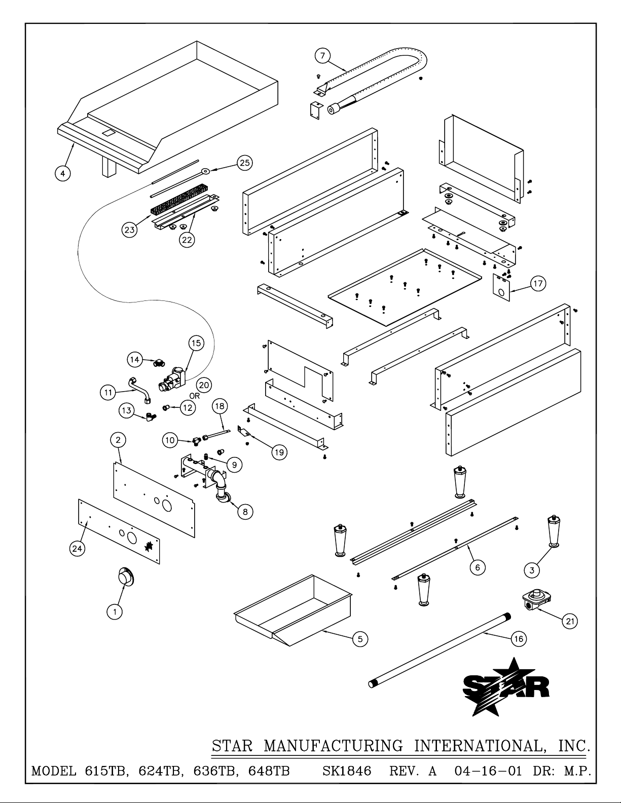
PARTS LIST EFFECTIVE 4/26/01
(2T-Y7590 = Stem)
T
T
11/08/06 rb
2F-Y7052
MODELS 8G-615TB & 8G-624TB STAR-MAX™ GAS GRIDDLES
Key
Number
1 2R-Z1273 (615TB/624TB) 1/2 KNOB-CONTROL
2 G3-Z1318 (615TB) 1 FRONTPANEL
G3-Z1315 (624TB) 1 FRONTPANEL
3 2A-Z0314 4 LEG
4 G3-GD0000 (615TB) 1 GRIDDLE PLATE ASSEMBLY
G3-GD0001 (624TB) 1 GRIDDLE PLATE ASSEMBLY
5 G3-Y7046 1 GREASE DRAWER GRIDDLE
6 G3-Y7047 2 SLIDE DRAWER
7 G3-624008 (615TB/624TB) 1/2 BURNER ASSEMBLY
8 G3-GD0018 (615TB) 1 MANIFOLD ASSEMBLY COMPLETE
G3-GD0019 (624TB) 1 MANIFOLD ASSEMBLY COMPLETE
9 2P-1453 1 PLUG-PIPE
10 2V-6671 (615TB/624TB) 1/2 VALVE-PILOT
11 G3-Y8852 (615TB) 1 TUBE ORIFICE
G3-T1022 (624TB) 2 TUBE ORIFICE
12 2J-Y7216 (615TB/624TB) 1/2 HOOD BURNER #47 NAT
13 2A-9369 (615TB/624TB) 1/2 ORIFICE-FITTING
14 2K-Y7111 (615TB/624TB) 1/2 FITTING COMPRESSION
15 2T-Z4293 (615MB/624MB) 1/2 THERMOSTAT
16 2K-Y7123 1 INLET PIPE
17 G3-Y7252 1 INLET PIPE SUPPORT
18 G3-Y7355 (615TB/624TB) 1/2 TUBE-PILOT
19 G3-Y7356 (615TB/624TB) 1/2 PILOT BRACKET
20 2J-Y7250 (615TB/624TB) 1/2 ORIFICE #55 L.P.
21 2J-Y7589 1 REGULATOR-PRESSURE (CONVERTIBLE)
22 G3-Z4398 (615TB/624TB) 1/2 BULB-CLAMP
23 G3-Y9531 (615TB/624TB) 1/2 INSULATOR
24 2M-Z1294 (615TB) 1 FACEPLATE 15", THERMOSTAT
2M-Z1291 (624TB) 1 FACEPLATE 24", THERMOSTAT
25 G3-GD0036 (615TB/624TB) 1/2 TUBE-WASHER ASSY.
Part
Number
Per
Unit
Description
Number
IMPORTANT: WHEN ORDERING, SPECIFY VOLTAGE OR TYPE GAS DESIRED PAGE
Some items are included for illustrative purposes only and in certain instances may not be available.
INCLUDE MODEL AND SERIAL NUMBER OF
Star Manufacturing International, Inc.
21
1
2
Page 12

PARTS LIST EFFECTIVE 4/26/01
(2T-Y7590 = Stem)
TT11/08/06 rb
2F-Y7052
MODELS 8G-636TB & 8G-648TB STAR-MAX™ GAS GRIDDLES
Key
Number
1 2R-Z1273 (636TB/648TB) 3/4 KNOB-CONTROL
2 G3-Z1312 (636TB) 1 FRONTPANEL
G3-Z1303 (648TB) 1 FRONTPANEL
3 2A-Z0314 4 LEG
4 G3-GD0002 (636TB) 1 GRIDDLE PLATE ASSEMBLY
G3-GD0003 (648TB) 1 GRIDDLE PLATE ASSEMBLY
5 G3-Y7046 1 GREASE DRAWER GRIDDLE
6 G3-Y7047 2 SLIDE DRAWER
7 G3-624008 (636TB/648TB) 1/2 BURNER ASSEMBLY
8 G3-GD0020 (636TB) 1 MANIFOLD ASSEMBLY COMPLETE
G3-GD0021 (648TB) 1 MANIFOLD ASSEMBLY COMPLETE
9 2P-1453 1 PLUG-PIPE
10 2V-6671 (636TB/648TB) 3/4 VALVE-PILOT
11 G3-T1022 (636TB/648TB) 3/4 ORIFICE TUBE
12 2J-Y7216 (636TB/648TB) 3/4 HOOD BURNER #47 NAT
13 2A-9369 (636TB/648TB) 3/4 ORIFICE-FITTING
14 2K-Y7111 (636TB/648TB) 3/4 FITTING COMPRESSION
15 2T-Z4293 (636MB/648MB) 3/4 THERMOSTAT
16 2K-Y7123 1 INLET PIPE
17 G3-Y7252 1 INLET PIPE SUPPORT
18 G3-Y7355 (636TB/648TB) 3/4 TUBE-PILOT
19 G3-Y7356 (636TB/648TB) 3/4 PILOT BRACKET
20 2J-Y7250 (636TB/648TB) 3/4 ORIFICE #55 L.P.
21 2J-Y7589 1 REGULATOR-PRESSURE (CONVERTIBLE)
22 G3-Z4398 (636TB/648TB) 3/4 BULB-CLAMP
23 G3-Y9531 (636TB/648TB) 3/4 INSULATOR
24 2M-Z1286 (636TB) 1 FACEPLATE 36", THERMOSTAT
2M-Z1278-1 (648TB) 1 FACEPLATE 48", THERMOSTAT LEFT
2M-Z1278-2 (648TB) 1 FACEPLATE 48", THERMOSTAT RIGHT
25 G3-GD0036 (636TB/648TB) 3/4 TUBE-WASHER ASSY.
Part
Number
Per
Unit
Description
Number
IMPORTANT: WHEN ORDERING, SPECIFY VOLTAGE OR TYPE GAS DESIRED PAGE
Some items are included for illustrative purposes only and in certain instances may not be available.
INCLUDE MODEL AND SERIAL NUMBER OF
Star Manufacturing International, Inc.
22
2
2
 Loading...