

Page 1
Star
Manufacturing
Int ernational Inc.
10 Sunnen Drive
St. Louis, MO 63143
Phone: (314) 781-2777
Fax: (314) 781-3636
2M-Z1383 Rev. B 3/27/03
Installat ion
and
Operating
Instructions
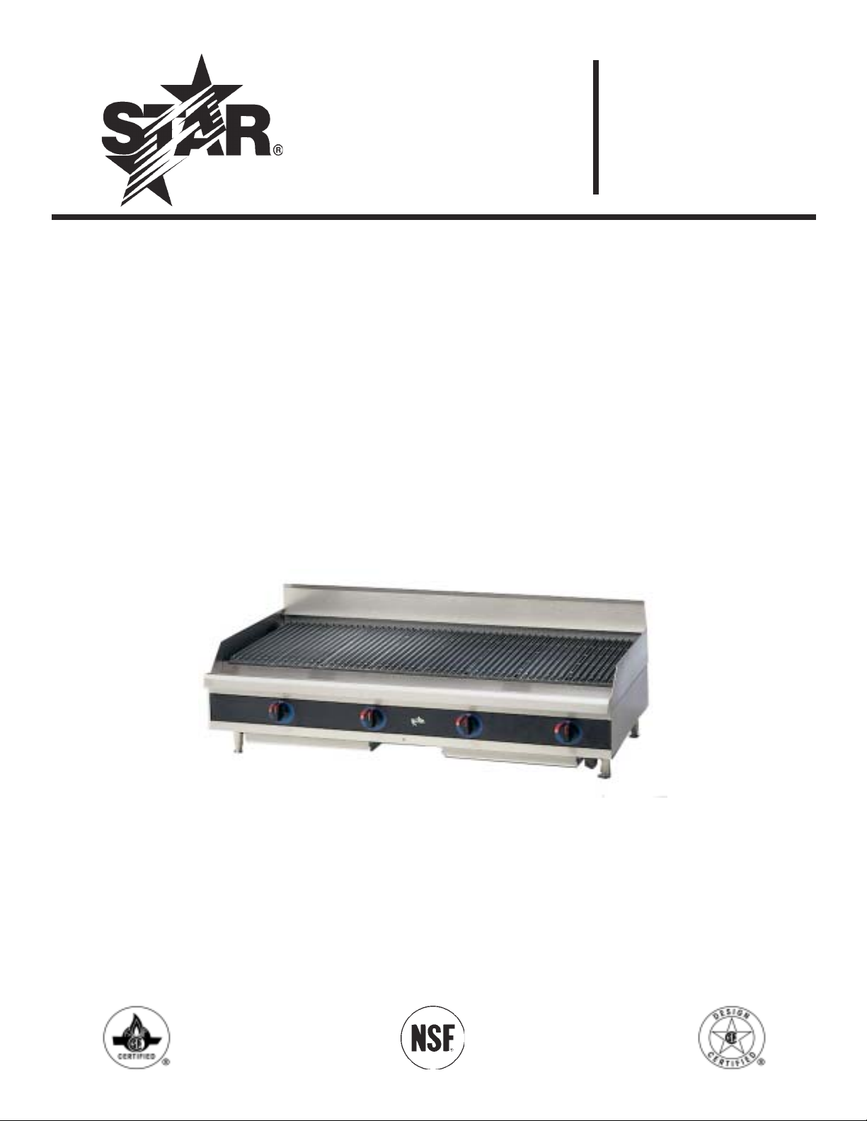
STAR-MAX GAS CHARBROILER
MODELS
6015CBA 6024CBA
6036CBA 6048CBA
6115RCBA 6124RCBA
6136RCBA 6148RCBA
6048 CBA
1
Page 2

SAFETY SYMBOL
This symbol is intended to alert the user t o the presence of important
operating and maintenance instr uctions in t he manual accompanying
the appliance.
RETAIN THIS MAN UAL FOR FU TURE REFERENCE
N OTICE
Using any part other t han genuine Star factory supplied parts relieves
the manufacturer of all liability.
N OTICE
Star reserves the right to change specifications and product design
without notice. Such revisions do not entitle the buyer t o corresponding changes, improvements, additions or replacements for
previously purchased equipment.
MAIN TENAN CE AN D REPAIRS
Contact your local authorized service agent for ser vice or required maintenance. Refer to the authorized service
cent er listing provided with the unit. The St ar Service Help Desk (1-800-807-9054) is available during normal
business hour s to answ er any quest ions that may ar ise. Please have your model number and ser ial number for faster
service.
2
Page 3
GEN ERAL IN STALLATION DATA
CAUTION
This equipment is designed and sold for commercial
use only by personnel trained and experienced in its
operation and is not sold for consumer use in and
around the home nor for use directly by the general
public in food service locations. For equipment to be
used by the general public, please contact the factor y.
The Star-M ax ser ies gas charbr oiler is equipped for the
type of gas indicated on the nameplate mounted on
the front panel. All units are shipped from the factory
for use wit h natur al gas. The unit can easily be converted
for use wit h pr opane gas: see propane gas.
-IMPORTAN T-
IN ST ALLATIO N : IN STALL IN N O N -CO MBU STIBLE
LOCATION S ON LY! Clear ance from noncombustible constr uction must be 6" from back and
sides.
The inst allat ion of t he Appliance must conform
to the NATIO N AL FUEL GAS CO D E "AN SI
Z 223.1 - LATEST ED IT IO N " AN D ALL LO CAL
GAS COMPAN Y RULES AN D
REGULATION S.
IN CAN ADA IN STALLATION SHALL BE IN
ACCORDAN CE WITH THE CURRENT
CAN /CGA-B149.1 NATURAL GAS
INSTALLATION CODE OR CAN /CGAB149.2 PROPAN E INSTALLATION CO DE
AN D LO CAL CO DES W HERE APPLICABLE.
FO R YOUR SAFETY
DO N OT STO RE OR USE GASOLIN E OR
OTHER FLAMMABLE VAPO RS AND
LIQUIDS IN THE VICINITY OF THIS O R
AN Y OTHER APPLIAN CE. KEEP THE
APPLIAN CE AREA CLEAR AN D FREE FRO M
CO MBUSTIBLES.
This appliance, its pressur e r egulator and its individual
shutoff valve must be disconnect ed from the gas
supply piping system during any pressure testing of t hat
system at test pressures in excess of 1/2 PSIG. This
appliance and it s pressure regulator must be isolated
fr om t he gas suppl y piping system by closing its indivi dual
manual shutoff valve during any pressur e t esting of the
gas supply piping system at test pressur es equal to or
less t han 1/2 PSIG. For your prot ection, w e recomm end
a qualified installing agency inst all this appliance. They
should be familiar wit h gas installations and your local
gas requirements. In any case, your gas company
should be called to approve the final inst allation. In
addit ion, there should be posted, in a prominent
location, detailed instructions to be follow ed in the
event the operator smells gas. Obtain t he inst ructions
from the local gas supplier.
LEVELIN G UN IT
This charbroiler is supplied w ith 4 feet which must be
screwed into the body. Level unit by adjust ing the (4)
feet which have an adjustment of 1-3/4" for accurate
and perfect line-up wit h other units.
CAUTION
DO N OT IN STALL WITHOUT ATTACHIN G
FEET - DO N OT REMOVE FEET.
WARNIN G: Improper installation,
adjust ment, alter ation, service or maint enance
can cause property damage, injury or deat h.
Read the installation, operating and
maint enance instructions thoroughly before
installing or servicing the equipment .
GAS IN PUT TO CHARBROILER:
Models 6015CBA and 6115RCBA 25,000 BTU/HR
Models 6024CBA and 6124RCBA 50,000 BTU/HR
25,000 BTU/HR/BURN ER
Models 6036CBA and 6136RCBA 75,000 BTU/HR
25,000 BTU/HR/BURN ER
Models 6048CBA and 6148RCBA 100,000 BTU/HR
25,000 BTU/HR/BURN ER
3
Page 4

GAS PIPIN G
Gas piping shall be of such size and so installed as to
provide a supply of gas sufficient t o meet the full gas
input o f the appliance. If t he appliance is to be connect ed
to exist ing piping, it shall be checked to determine if it
has adequate capacity. Joint compound (pipe dope)
shall be used sparingly and only on the male t hreads of
the pipe joints. Such compounds shall be resistant t o
the action of L.P. gases. WARN ING: Any loose dir t or
metal part icles which ar e allow ed to ent er the gas lines
on this appliance will damage t he valve and affect its
operation. When installing this appliance, all pipe and
fittings must be free from all internal loose dirt.
GAS PRESSURE REGULATOR
A convert ible pressur e regulator is pr ovided wit h each
charbroiler. It should be connected to the inlet pipe at
the rear of the unit. The gas supply is then connected
to it. It is shipped set for 6" water column manifold
pressure for use wit h natural gas. Allow 6" clearance
from back of unit t o wall fro servicing and inst allation.
CONN ECTIN G GAS SU PPLY LIN E
The gas inlet of the charbroiler is sealed at the factory
to prevent entr y of dirt. Do not remove this seal until
the actual connection is made to the gas supply line.
CHECKIN G FOR GAS LEAKS
Soap and water solution or ot her material acceptable
for the purpose, shall be used in locating gas leakage.
Matches, candle flame or other sources of ignition
shall not be used for this purpose. Check entire piping
system for leaks.
PILOT LIGHTIN G IN STRUCTION S
The charbroiler is equipped with standing pilots, and
should be lit immediately aft er the gas is turned on.
1. Turn off main valve to unit and wait 5 minutes to
clear gas.
2. Turn off all knobs and pilot valves.
3. Turn on main valve and light all pilots.
4. Turn burner knobs t o desired setting.
5. To turn burners off, turn knobs off.
SHUTTIN G DOWN IN STRUCTION S
1. Turn the burner valve knobs to the off position to
turn burners off.
PILOT LIGHT REGULATION
The pilot lights on this broiler have been t urned off at
the facto ry. Adjust pilot light flam es as sm all as possible,
but high enough to light burner immediately when
burner valve is turned on high.
MAN UAL SHU T OFF VALVE
A manual shut off valve should be installed upstream
fr om t he manifold and w ithin six feet o f the charbr oiler.
PROPAN E GAS
This charbroiler is equipped with fixed orifice hoods
and is shipped from t he factor y for use wit h natur al gas.
To convert to propane gas, install the burner orifice
hoods supplied behind the front panel as follow s:
1. Remove grill, r adiant s and burners.
2. Remove the burner orifice hoods and install the
orifice hoods supplied.
3. Replace the burners, radiants, and grill.
4. Set manifold pressure to (10) inch water column.
A 1/8" pipe plug on the burner manifold can be
removed for attaching a pressure gauge. Remove
t he slot ted, or hex-threaded plug fro m the pr essure
regulator. Invert the plug and r e-install. The
lett er s "LP" should now be visible on t he plug. The
regulator is now set for 10" (25.4 cm) wat er
column.
BURN ER OPERAT ION
To ignit e burners, turn burner valve knob to "HI"
position. Each burner is controlled by an individual
high-low, on-off valve. An infinite number of broiling
temperatures may be obtained by turning the burner
valve knob to any position betw een high and low.
BURN ER AD JUSTM EN T
1. Turn burner valve knob to "HI" position.
2. Slowly decrease openings of air shut t ers to give a
soft blue flame having luminous tips, then slow ly
increase openings to a point w her e t he yellow tips
disappear and a hard blue flame is obtained.
4
Page 5

EX H AUST CAN OPY
Open heart h br oilers inherently create a good deal of
heat and smoke and should be installed under an
efficient exhaust hood with flame proof filt ers. A
vertical distance of not less than 48" shall be provided
betw een the top of the appliance and filt ers or any
other combustible material.
AIR SUPPLY
Provisions for adequate air supply must be provided.
OPERATIN G IN STRUCTION S
LIGHTIN G
When broiler is first lit, it w ill smoke unt il the
preservation oils and impurities are burned off.
BROILIN G
Turn valves on and pre-heat unit on "HI" before
attempting to broil. You will have to experiment w ith
t he grill set t ings and t he valve sett ings for your part icular
meat products. W e r ecommend that you set the grat e
at the full tilt posit ion to start wit h. This posit ion allow s
the grease to r un down the grat e into t he grease tray,
reducing flare ups. Check water pans frequently and
add a sufficient amount of w ater w hen necessary. Hot
wat er vapors r ising from the water pans and through
the combustion chamber helps reduce flare ups.
Exercise care when using your broiler.
TILTIN G THE GRATE
Raise or low er the gr ate to the next step by lifting the
gr ate at t he back of the charbroiler where the grat e
rests. Use potholders or gloves to reposit ion.
ADJUSTIN G HEAT PATTERN
It is possible through this arrangement to have a high
heat or sear ing section, while having a lo w heat finishing
or holding section. For t he sear ing operation, set the
valves for the section at a position of "HI" or close to
it. For holding or finishing, set the valves closer to t he
"LOW" position on the dial. You select the heat
pattern you like, and set the valves accordingly.
CLEAN IN G
Clean regularly. Remove gr ate section to sink for
washing. Brush out carboned particles. Remove and
w ash w at er pan. W ipe ext erior sur faces wit h deter gent
and a cloth. A non-abrasive cleaner can be used on
caked areas.
WATER PAN
The w ater pan is located at the bottom of t he unit, and
is easily removed from the front of the unit. Water
should be added to the water pan and replaced as
necessary. The water pan helps prevent flare ups and
catches grease.
AIR IN TAKES IN BOTTOM
Air for combustion enters from the bottom of the
unit. D o not obstruct this area.
MAIN TEN AN CE AN D REPAIRS
Contact t he factory or one of its representatives or a
local ser vice company for service or maintenance if
required.
CAUTION
CHARBROILERS ARE HOT! N EVER ATTEMPT
TO CHAN GE THE GRILL POSITION WH ILE
M EAT PROD UCT S ARE COOKI N G. FLARE-U PS
CAN O CCU R U N EX PECTED LY. T URN OFF TH E
CHARBROILER AND ALLOW IT TO COOL.
RET AIN TH IS MAN UAL FOR FUTU RE REFEREN CE
PART NO. 2M-Z 1383 Rev. B 3/27/03
5
Page 6

Visi t o ur Websi t e at: www.star -mfg.com Email : ser vice@star -mfg.com Fo r Fax-On-Deman d Li t e rat ure: (800) 80 7-981 4
THOROUGHLY INSPECT YOUR UNIT ON ARRIVAL
This unit has been tested for proper operation before leaving our plant to insure delivery of your unit in perfect condition. However, there are instances in which
the unit may be damaged in transit. In the event you discover any type of damage to your product upon receipt, you must immediately contact the transportation
company who delivered the item to you and initiate your claim with same. If this procedure is not followed, it may affect the warranty status of the unit.
LIMITED EQUIPMENT WARRANTY
All workmanship and material in Star products have a one (1) year limited warranty on parts & labor in the United States and Canada. Such warranty is limited
to the original purchaser only and shall be effective from the date the equipment is placed in service. Star's obligation under this warranty is limited to the repair
of defects without charge, by the factory authorized service agency or one of its sub-agencies. Models that are considered portable (see below) should be taken
to the closest Star service agency, transportation prepaid.
> Star will not assume any responsibility for loss of revenue.
> On all shipments outside the United States and Canada, see International Warranty.
* The warranty period for the JetStar series six (6) ounce popcorn machines is two (2) years.
* The warranty period for the Chrome-Max Griddles is five (5) years on the griddle surface. See detailed warranty provided with unit.
* The warranty period for Teflon/Dura-Tec coatings is one year under normal use and reasonable care. This warranty does not apply if damage occurs to Teflon/
Dura-Tec coatings from improper cleaning, maintenance, use of metallic utensils, or abrasive cleaners. This warranty does not apply to the “non-stick”
properties of such materials.
> This warranty does not apply to "Special Products" but to regular catalog items only. Star's warranty on "Special Products" is six (6) months on parts and
ninety (90) days on labor.
> This warranty does not apply to any item that is disassembled or tampered with for any purpose other than repair by a Star Authorized Service Center or the
Service Center's sub-agency.
> This warranty does not apply if damage occurs from improper installation, misuse, wrong voltage, wrong gas or operated contrary to the Installation and Operating
instructions.
>This warranty is not valid on Conveyor Ovens unless a "start-up/check-out" has been performed by a Factory Authorized Technician.
PARTS WARRANTY
Parts that are sold to repair out of warranty equipment are warranted for ninety (90) days. The part only is warranted. Labor to replace the part is chargeable
to the customer.
SERVICES NOT COVERED BY WARRANTY
1. Travel time and mileage rendered beyond the 50 mile radius limit
2. Mileage and travel time on portable equipment (see below)
3. Labor to replace such items that can be replaced easily during a daily cleaning
routine, ie; removable kettles on fryers, knobs, grease drawers on griddles, etc.
4. Installation of equipment
5. Damages due to improper installation
6. Damages from abuse or misuse
7. Operated contrary to the Operating and Installation Instructions
8. Cleaning of equipment
9. Seasoning of griddle plates
PORTABLE EQUIPMENT
Star will not honor service bills that include travel time and mileage charges for servicing any products considered "Portable" including items listed below. These
products should be taken to the Service Agency for repair:
* The Model 510F Fryer.
* The Model 526TO Toaster Oven.
* The Model J4R, 4 oz. Popcorn Machine.
* The Model CFS Series Food Steamer.
* The Model 526WO Warming Oven.
* The Model 518CM & 526CM Cheese Melter.
* The Model 12MC & 15MC & 18MCP Hot Food Merchandisers.
* The Model 12NCPW & 15NCPW Nacho Chip/Popcorn Warmer.
* All Hot Dog Equipment except Roller Grills & Drawer Bun Warmers.
* All Nacho Cheese Warmers except Model 11WLA Series Nacho Cheese Warmer.
* All Condiment Dispensers except the Model CSD & HPD Series Dispenser.
* All Specialty Food Warmers except Model 130R, 500, 11RW Series, and 11WSA Series.
10 . Voltage conversions
11 . Gas conversions
12 . Pilot light adjustment
13 . Miscellaneous adjustments
14 . Thermostat calibration and by-pass adjustment
15 . Resetting of circuit breakers or safety controls
16 . Replacement of bulbs
17 . Replacement of fuses
18 . Repair of damage created during transit, delivery, &
installation OR created by acts of God
ALL:
* Pop-Up Toasters
* Butter Dispensers
* Pretzel Merchandisers
* Pastry Display Cabinets
* Nacho Chip Merchandisers
* Accessories of any kind
* Sneeze Guards
* Pizza Ovens
* Heat Lamps
* Hot Cups
* Pumps
The foregoing warranty is in lieu of any and all other warranties expressed or implied and constitutes the entire warranty.
FOR ASSISTANCE
Should you need any assistance regarding the Operation or Maintenance of any Star equipment; write, phone, fax or email our Service Department.
In all correspondence mention the Model number and the Serial number of your unit, and the voltage or type of gas you are using.
Part# 2M-4497-2 10/02 RB
6
Page 7
10
6
7
8
9
27
14
23
2
15 19
20
16
17
22
25
21
18 24
1
3
4
5
11
26
12
13
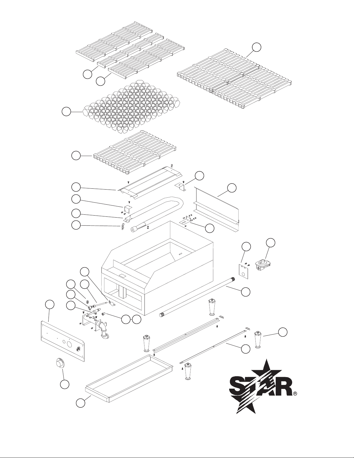
Model: 6015CBA, 6024CBA, 6036CBA, 6048CBA
STAR MANUFACTURING INTERNATIONAL, INC.
SK1554, Rev. A 11/28/2011
252627
Updated 04-17-08 RB
7
Page 8
PARTS LIST November 28, 2011, Rev. B
Updated 04-17-08 rb
2F
HOOD BURNER LP # 53
25 H3-Y7095 1/2/3/4 Bracket Burner ALL
26 H3-Y7570 1/2/3/4 Cover, Burner Front ALL
27 H3-Y7569 1/2/3/4 Cover, Burner Back ALL
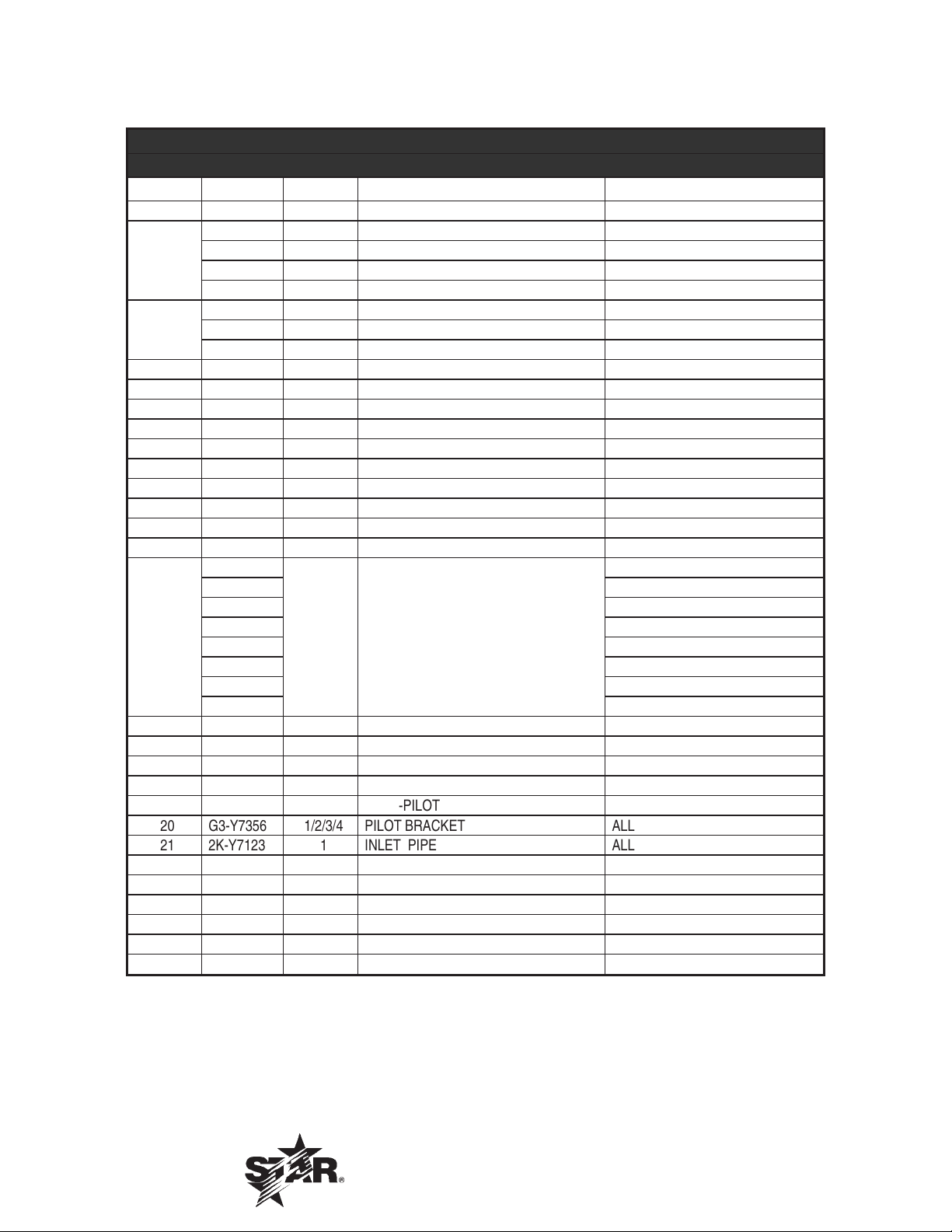
Star-Max Gas Lava Rock Charbroiler - 15”, 24”, 36”, 48”
Model: 6015CBA, 6024CBA, 6036CBA AND 6048CBA
Fig No Part No. Qty Description Application
1 2R-Z0934 1/2/3/4 KNOB-CONTROL ALL
H3-Z1322 1 FRONT PANEL 6015CBA
H3-Z1321 1 FRONT PANEL 6024CBA
2
H3-Z1320 1 FRONT PANEL 6036CBA
H3-Z1264 1 FRONT PANEL 6048CBA
H3-T1026 1 GREASE DRAWER 6015CBA
3
H3-Y7045 1/2 GREASE DRAWER 6024CBA/6048CBA
H3-Y7044 1 GREASE DRAWER 6036CBA
4 G3-Y7047 2/2/2/4 SLIDE DRAWER ALL
5 2A-Z0314 4 LEG ALL
6 2F-Y8831 1 GRATE 3” 6015CBA
7 2F-Y8830 2/4/6/8 GRATE 6” ALL
8 2F-Y7193 1/2/3/4 LAVA ROCK 2” 8 LBS. ALL
9 2F-Y7141 1/1/2 GRATE LAVA ROCK 12x17-1/4” 6015CBA/ 6036CBA/6048CBA
10 2F-Z3273 2/2/2 GRATE LAVA ROCK 10.5x14-1/4” 6024CBA/ 6036CBA/6048CBA
11 H3-624086 1/2/3/4 BURNER GUARD ASSEMBLY ALL
12 2F-Y7052 1/2/3/4 BURNER ASSEMBLY ALL
13 2A-Y6694 1/2/3/4 CLIP ALL
G3-624038
G3-624037 6024CBA AGA
G3-624039 6036CBA AGA
14
15 2P-1453 1 PLUG-PIPE ALL
16 2V-6671 1/2/3/4 VALVE-PILOT ALL
17 2V-Y8832 1/2/3/4 VALVE-BURNER ALL
18 2J-Y8838 1/2/3/4 HOOD BURNER NAT. #45 ALL
19 G3-Y7355 1/2/3/4
20 G3-Y7356 1/2/3/4 PILOT BRACKET ALL
21 2K-Y7123 1 INLET PIPE ALL
22 G3-Y7252 1 INLET PIPE SUPPORT ALL
23 2J-Y7589 1 PRESSURE REGULATOR ALL
24 2J-Y7136 1/2/3/4 ORIFICE LP. #53 ALL
25 H3-Y7095 1/2/3/4 BRACKET BURNER CB ALL
26 H3-Y7570 1/2/3/4 COVER, BURNER FRONT ALL
27 H3-Y7569 1/2/3/4 COVER, URNER BACK ALL
H3-624106 6015CBA CGA
H3-624107 6024CBA CGA
H3-648007 6048CBA AGA
H3-624108 6036CBA CGA
H3-648010 6048CBA CGA
1 GUARD WELD ASSEMBLY
TUBE-PILOT ALL
6015CBA AGA
IMPORTANT: WHEN ORDERING, SPECIFY VOLTAGE OR TYPE GAS DESIRED PAGE 1
INCLUDE MODEL AND SERIAL NUMBER OF 1
Some items are included for illustrative purposes only and in certain instances may not be available.
Star Manufacturing International, Inc.
8
 Loading...