

Star 601SPRF, 602HWWF, 602HF, 602HWF, 602HF-SU Installation And Operation Instructions Manual
...Page 1
GAS
HOT PLATES
MODEL
601SPRF
602HWF, 602HWWF, 602HF, 602HF-SU
603HWF, 603HWWF
604HF, 604HF-SU
606HF, 606HF-SU
Installation and
Operation
604HF
Instructions
2M-Z16006 Rev. A 10/10/14
Page 2

Please record the model number, serial number, voltage and purchase date in the area below and have it ready when
SAFETY SYMBOL
Using any part other than genuine Star factory supplied parts relieves the
manufacturer of all liability.
Star reserves the right to change specications and product design without
notice. Such revisions do not entitle the buyer to corresponding changes,
improvements, additions or replacements for previously purchased
equipment.
Due to periodic changes in designs, methods, procedures, policies and
regulations, the specications contained in this sheet are subject to change
without notice. While Star International Holdings Inc., Company exercises
good faith efforts to provide information that is accurate, we are not
responsible for errors or omissions in information provided or conclusions
reached as a result of using the specications. By using the information
provided, the user assumes all risks in connection with such use.
These symbols are intended to alert the user to the presence of
important operating and maintenance instructions in the manual
accompanying the appliance.
RETAIN THIS MANUAL FOR FUTURE REFERENCE
NOTICE
MAINTENANCE AND REPAIRS
Contact your local authorized service agent for service or required maintenance.
you call to ensure a faster service.
Authorized Service Agent Listing
Model No.
Serial No.
Voltage
Purchase Date
Reference the listing provided with the unit
or
for an updated listing go to:
Website: www.star-mfg.com
E-mail Service@star-mfg.com
Service Help Desk
Business 8:00 am to 4:30 p.m. Central Standard Time
Hours:
Telephone: (314) 678-6303
Fax: (314) 781-2714
E-mail Parts@star-mfg.com
Service@star-mfg.com
Warranty@star-mfg.com
Website: www.star-mfg.com
Mailing Address: Star International Holdings Inc., Company
10 Sunnen Drive
St. Louis, MO 63143
U.S.A
2
Page 3
CAUTION
GENERAL INSTALLATION DATA
This equipment is designed and sold for commercial use only by personnel trained and experienced
in its operation and is not sold for consumer use in and around the home nor for use directly by the
general public in food service locations. For equipment to be used by the general public,
please contact the factory.
This gas appliance is equipped for the types of gas indicated on the nameplate mounted on the front
panel. It is shipped adjusted for use on natural gas.
The installation of the Appliance should conform to the NATIONAL FUEL GAS
CODE "ANSI Z223.1 - LATEST EDITION" AND ALL LOCAL GAS COMPANY
RULES AND REGULATIONS.
IN CANADA INSTALLATION SHALL BE IN ACCORDANCE WITH THE CURRENT
CAN/CGA-B149.1 NATURAL GAS INSTALLATION CODE OR CAN/CGA-B149.2
PROPANE INSTALLATION CODE AND LOCAL CODES WHERE APPLICABLE.
WARNING: Improper installation, adjustment, alteration, service or maintenance can
cause property damage, injury or death. Read the installation, operating and maintenance
instructions thoroughly before installing or servicing the equipment.
FOR YOUR SAFETY
DO NOT STORE OR USE GASOLINE OR OTHER FLAMMABLE VAPORS AND LIQUIDS IN
THE VICINITY OF THIS OR ANY OTHER APPLIANCE. KEEP THE APPLIANCE AREA CLEAR
AND FREE FROM COMBUSTIBLES.
This appliance, its pressure regulator and its individual shutoff valve must be disconnected from the
gas supply piping system during any pressure testing of that system at test pressures in excess of 1/2
PSIG. This appliance and its pressure regulator must be isolated from the gas supply piping system by
closing its individual manual shutoff valve during any pressure testing of the gas supply piping system
at test pressures equal to or less than 1/2 PSIG. For your protection, we recommend a qualied
installing agency install this appliance. They should be familiar with gas installations and your local
gas requirements. In any case, your gas company should be called to approve the nal installation.
In addition, there should be posted, in a prominent location, detailed instructions to be followed in the
event the operator smells gas. Obtain the instructions from the local gas supplier.
LEVELING UNIT
Units are shipped with feet detached. To attach feet, remove the grates, lay unit on it's side and screw
feet into sockets on bottom. Level unit by adjusting the (4) feet which have an adjustment of 1-3/4" for
accurate and perfect line-up with other Star-Max series units.
DO NOT REMOVE FEET.
CAUTION
2M-Z16006; Star-Max Gas Hot Plates
GAS PIPING
Gas piping shall be new, clean and of such size and so installed as to provide a supply of gas
sufcient to meet the full gas input of the appliance. If the appliance is to be connected to existing
piping, it shall be checked to determine if it has adequate capacity. Joint compound (pipe dope) shall
be used sparingly and only on the male threads of the pipe joints. Such compounds shall be resistant
to the action of L.P. gases.
WARNING: Any loose dirt or metal particles which are allowed to enter the gas lines on the appliance
will damage the automatic valve and affect its operation. When installing this appliance, all pipe and
ttings must be free from all internal loose dirt.
CLEARANCE
Minimum wall clearances for the sides and back of the models contained in this manual shall
be as follows:
Combustible Non-Combustible
Wall Wall
Hotplates 9" 0"
Stock Pot Range 14" 0"
Page 4

PRESSURE REGULATOR
A convertible pressure regulator set at 6" water column for use on natural gas is furnished. (For
LP models the regulator is set for 10" water column pressure.) Attach the regulator to the supply
pipe, located at the back of the unit, make sure gas ow arrow on regulator is pointing towards
manifold. The gas supply is then connected to the regulator. A 1/8" tap is furnished on the manifold
for checking pressure. The manifold is accessible by removing the front panel.
MANUAL SHUT OFF VALVE
A manual shut off valve should be installed upstream from the unit and within six feet of the
appliance, and is not provided.
CONNECTING GAS SUPPLY LINE
The gas inlet on this appliance is sealed at the factory to prevent entry of dirt. Do not remove this
seal until the actual connection is made to the gas supply line.
CHECKING FOR GAS LEAKS
Soap and water solution or other material acceptable for the purpose, shall be used in locating
gas leakage. Matches, candle ame or other sources of ignition shall not be used for this purpose.
AIR SUPPLY
Provisions for adequate air supply must be furnished.
AIR INTAKES IN BOTTOM
Make certain the air intake openings in the bottom of the appliance are not obstructed. They are
essential for proper combustion and operation of the appliance.
EXHAUST CANOPY
It is essential that facilities be provided to carry off fumes and gases.
GAS INPUT OF OPEN TOP RANGES
For Natural Gas: All models except 601SPRF-22,000 BTU/HR for each burner. Model 601SPRF55,000 BTU/HR for each burner. Regulator output pressure set at 6" water column.
For Propane Gas: All models except 601SPRF-25,000 BTU/HR for each burner.
Model 601SPRF-45,000 BTU/HR for each burner. Regulator output pressure
set at 10" water column.
Note: The appliance is equipped with orice hoods that is stated on the units
nameplate. For natural units a separate set of hoods will be provided for use on
propane gas. The propane hoods are located on the front panel.
Factory set LP models do not include the natural gas hoods.
2M-Z16006; Star-Max Gas Hot Plates
Page 5
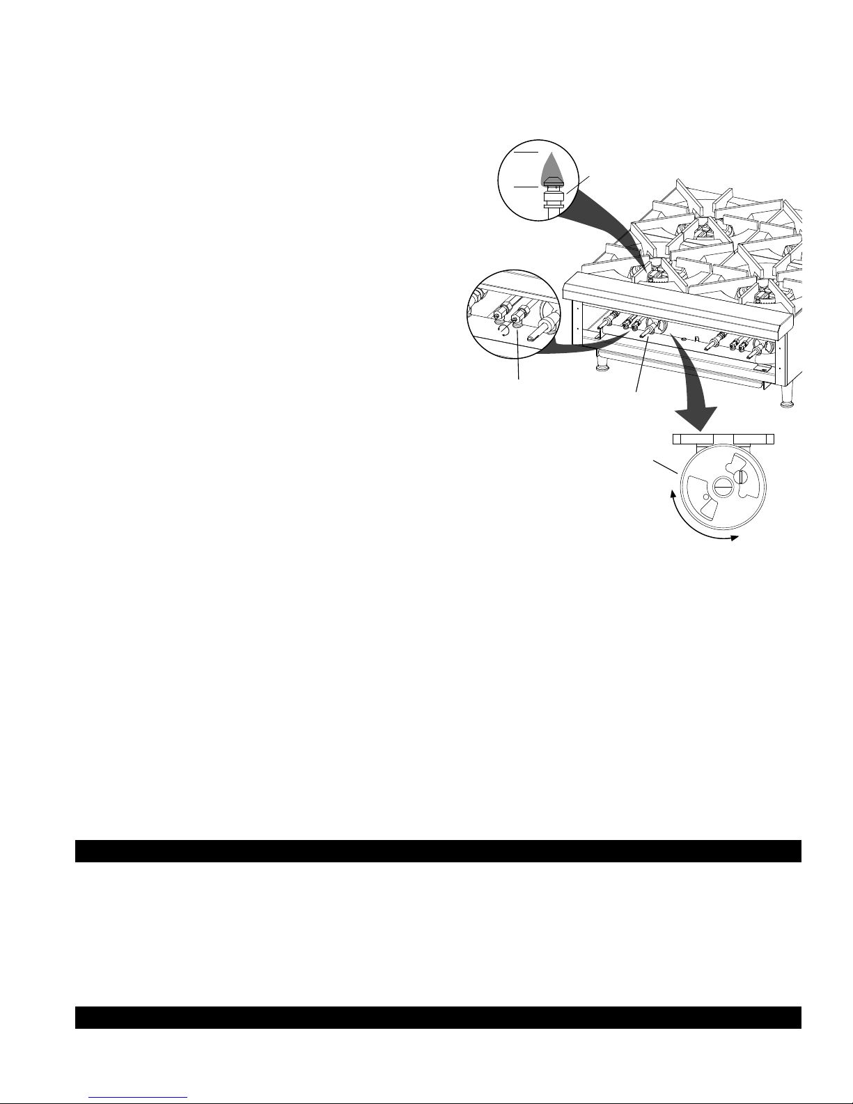
LIGHTING INSTRUCTIONS
1/4”
Flame
Pilot Valve
Air Shutter
Control
Valve
Pilot
IL2426
The appliance is equipped with standing pilots; each pilot is located in front of the burner on Models 602HF, 602HWF,
and 606HF. On Models 602HF-SU, 604HF-SU and 606HF-SU the pilots for the front burners are located in front
of the burners, on the rear burners pilots are located on the side of the burners. On Model 601SPRF, the pilots are
located on the right side of each burner. Pilots should be lighted immediately after the gas is turned on by the manual
shutoff valve.
1. Turn control knobs to "OFF" position.
2. Light pilot with a lighted taper.
3 The pilot valves are located on the manifold installed at
the front of the unit behind the front panel. For access to
the valves
4. Loosen the set screws securing the knobs in position,
and remove the knobs. Remove the front panel, which is
attached to the frame with 4 sheet metal screws.
5. Turn the adjustment screws on the front of the pilot valves.
The pilots should be adjusted to blue short ame (1/4" high)
to have good ignition to the burners. Repeat for remaining
pilots.
6. If the pilot(s) is out turn off gas, wait 5 minutes and repeat
steps (1) through (5).
ADJUSTING BURNERS
7. With control valve for the front burner turned to full "ON" position, close
the air shutters to give a soft blue ame having luminous tips and open to a
point where the yellow tips disappear, then tighten the locking screws. Repeat
this procedure with the remaining burners.
8. Install the front panel to the front of the frame & reconnect and secure the knobs back
into position.
ADJUSTING UNIT FOR USE ON PROPANE GAS
Units are shipped with orices and pressure regulator for operation with natural gas (6" water column). To convert
unit from natural to propane gas follow these instructions (Note: LP models are factory set for propane gas and do
not require a conversion. these can be converted to natural gas using the natural gas orices and converting the
regulator to natural gas):
1. Set regulator outlet pressure to 10" water column. A 1/8" pipe plug on the manifold can be removed for attaching
a pressure gauge. Remove the slotted cover from the pressure regulator and invert the plug. Replace the cover
on the regulator and plug on the manifold. Regulator is now set at 10" W.C.
2. Remove natural gas orices, #44 for all models except 601SPRF, #.125 for 601SPRF, and install propane orices,
painted black, (#52 for all models except 601SPRF, #45 for 601SPRF) located in a bag on the outside of the front
panel. In order to remove natural gas orices:
a. Remove grates and burners.
b. Remove orices from the valves and from ttings on extended gas pipes, replace with the propane orices.
c. Install burners and grates.
OPERATING PROCEDURE
2M-Z16006; Star-Max Gas Hot Plates
Each burner will deliver up to 25,000 BTU/HR of heat on all models except 601SPRF (on 601SPRF each burner is
rated 55,000 BTU/HR for natural gas and 45,000 BTU/HR for propane) and is controlled by a manual On/Off valve.
The right control knob controls the front burner and the left control knob controls the rear burner on all models except
601SPRD. On the 601SPRD, the right control knob controls the inner burner and the left control knob controls the
outer burner. After the pilot is once lit and adjusted, the burners will ignite automatically by turning the control knob to
any position between On and Off.CLEANING THE EXTERIOR (Stainless Steel Only)
The exterior surface can be kept clean and attractive by regularly wiping it with a clean soft cloth. Any discoloration
can be removed with a non-abrasive cleaner. The burner grates and trough tray can be removed for cleaning.
MAINTENANCE AND REPAIRS
Contact the factory or one of its representatives or a local service company for service or maintenance if required.
Page 6

Visit our Website at: www.star-mfg.com Email: service@star-mfg.com
This unit has been tested for proper operation before leaving our plant to insure delivery of your unit in perfect condition. However, there are instances in which
the unit may be damaged in transit. In the event you discover any type of damage to your product upon receipt, you must immediately contact the transportation
company who delivered the item to you and initiate your claim with same. If this procedure is not followed, it may affect the warranty status of the unit.
All workmanship and material in Star products have a one (1) year limited warranty on parts & labor in the United States and Canada. Such warranty is limited
to the original purchaser only and shall be effective from the date the equipment is placed in service. Star's obligation under this warranty is limited to the repair
of defects without charge, by the factory authorized service agency or one of its sub-agencies. Models that are considered portable (see below) should be taken
to the closest Star service agency, transportation prepaid.
THOROUGHLY INSPECT YOUR UNIT ON ARRIVAL
LIMITED EQUIPMENT WARRANTY
> Star will not assume any responsibility for loss of revenue.
> On all shipments outside the United States and Canada, see International Warranty.
* The warranty period for the Ultra-Max, Hot Plates, Griddles, Charbroilers is (3) years parts & labor.
* The warranty period for the Star-Max, Charbroilers, Griddles, Hot Plates, Fryers & Finishing Oven is (2) years parts & labor.
* The warranty period for the JetStar six (6) ounce & Super JetStar eight (8) ounce series popcorn machines is two (2) years.
* ThewarrantyperiodfortheChrome-MaxGriddlesisve(5)yearsonthegriddlesurface.Seedetailedwarrantyprovidedwithunit.
* The warranty period for Dura-Tec coatings is one year under normal use and reasonable care. This warranty does not apply if damage occurs to
Dura-Teccoatingsfromimpropercleaning,maintenance,useofmetallicutensils,orabrasivecleaners,abrasivepads,productidentiersand
point-of-sale attachments, or any other non-food object tha comes in continuous contact with the roller coating. This warranty does not apply to the
“non-stick” properties of such materials.
> This warranty does not apply to "Special Products" but to regular catalog items only. Star's warranty on "Special Products" is six (6) months on parts
and ninety (90) days on labor.
> This warranty does not apply to any item that is disassembled or tampered with for any purpose other than repair by a Star Authorized Service Center or
the Service Center's sub-agency.
> This warranty does not apply if damage occurs from improper installation, misuse, wrong voltage, wrong gas or operated contrary to the Installation and
Operating instructions.
> This warranty is not valid on Conveyor Ovens unless a "start-up/check-out" has been performed by a Factory Authorized Technician.
Parts that are sold to repair out of warranty equipment are warranted for ninety (90) days. The part only is warranted, the labor to replace the part is NOT warranted.
SERVICES NOT COVERED BY WARRANTY
1. Traveltimeandmileagerenderedbeyondthe50mileradiuslimit
2. Mileage and travel time on portable equipment (see below)
3. Labor to replace such items that can be replaced easily during a daily cleaning
routine, ie; removable kettles on fryers, knobs, grease drawers on griddles, etc.
4. Installation of equipment
5. Damagesduetoimproperinstallation
6. Damages from abuse or misuse
7. Operated contrary to the Operating and Installation Instructions
8. Cleaning of equipment
9. Seasoning of griddle plates
Star will not honor service bills that include travel time and mileage charges for servicing any products considered "Portable" including items listed below.
These products should be taken to the Service Agency for repair:
* TheModel510FD,510FFFryer.
* TheModel526TOAToasterOven.
* TheModelJ4R,4oz.PopcornMachine.
*TheModel518CMA&526CMACheeseMelter.
* TheModel12MC&15MC&18MCPHotFoodMerchandisers.
* TheModel12NCPW&15NCPWNachoChip/PopcornWarmer.
* All Hot Dog Equipment except Roller Grills & Drawer Bun Warmers.
* All Nacho Cheese Warmers except Model 11WLA Series Nacho Cheese Warmer.
* All Condiment Dispensers except the Model HPD & SPD Series Dispenser.
* All Specialty Food Warmers except Model 130R, 11RW Series, and 11WSA Series.
* AllQCS/RCSSeriesToastersexcept Model QCS3 & RCS3 Series.
* All Fast Steamer Models except Direct Connect Series.
The foregoing warranty is in lieu of any and all other warranties expressed or implied and constitutes the entire warranty.
Should you need any assistance regarding the Operation or Maintenance of any Star equipment; write, phone, fax or email our Service Department.
In all correspondence mention the Model number and the Serial number of your unit, and the voltage or type of gas you are using.
PARTS WARRANTY
10. Voltage conversions
11. Gas conversions
12. Pilot light adjustment
13. Miscellaneous adjustments
14. Thermostat calibration and by-pass adjustment
15. Resettingofcircuitbreakersorsafetycontrolsorresetbuttons
16. Replacementofbulbs
17. Replacementoffuses
18. Repairofdamagecreatedduringtransit,delivery,&
PORTABLE EQUIPMENT
FOR ASSISTANCE
installationORcreatedbyactsofGod
ALL:
* Pop-Up Toasters
* Butter Dispensers
* Pretzel Merchandisers
(Model 16PD-A Only)
* Pastry Display Cabinets
* Nacho Chip Merchandisers
* Accessories of any kind
* Sneeze Guards
* Pizza Ovens
(Model PO12 Only)
* Heat Lamps
* Pumps-Manual
2M-Z16006; Star-Max Gas Hot Plates
2M-4497-2 11/21/14
Page 7

GAS HOTPLATE
MODEL 602-, 604-, 606-
STAR MANUFACTURING INTERNATIONAL, INC.
SK2594 REV. - 6/06/12
2
3
4
5
7
9
10
12
13
14
16
17
18
19
20
8
9
8
6
15
NAMEPLATE
11
22
21
24
26
25
1
2M-Z16006; Star-Max Gas Hot Plates
Page 8

STAR MANUFACTURING INTERNATIONAL, INC.
SK2595 REV. -
6/16/10
GAS HOTPLATE STEP-UP DESIGN
MODEL 602HD-SU, 604HD-SU, 606HD-SU
3
4
2
26
25
5
7
9
10
12
13
14 16
17
18
19
20
8
9
8
6
15
24
1
NAMEPLATE
23
11
22
21
2M-Z16006; Star-Max Gas Hot Plates
Page 9

PARTS LIST October 10, 2014, Rev A
MODEL: 602HF, 604HF, 606HF, 602HF-SU, 604HF-SU, 606HF-SU, 602HF-LP, 604HF-LP, 606HF-LP
Fig No Part No. Qty Description Application
1 I4-Z15484 2/4/6 KNOB ALL 602/604/606HF
I4-Z15485
2
3 2V-6671 2/4/6 VALVE-LINCOLN ALL 602/604/606HF
4 2V-Y8832 2/4/6 VALVE-MANUAL ALL 602/604/606HF
5
6 2A-Z0790 1/2/3 FITTING STRAIGHT ALL 602/604/606HF
7
8 2A-80400-27 2/4/6 ORIFICE #44 NATURAL ALL 602/604/606HF
9 2A-Y1255 2/4/6 ORIFICE #52 PROPANE ALL 602/604/606HF
10 2F-Z0747 2/4/6 VENTURI ALL 602/604/606HF
11 2I-Z0752 2/4/6 GASKET ALL 602/604/606HF
12 2F-Z0637 2/4/6 GRATE ALL 602/604/606HF
13 2F-Z0615 2/4/6 BURNER ALL 602/604/606HF
14
15
16
17 I4-602013 1/2/3 PILOT TUBE ASSEMBLY SHORT ALL 602/604/606HF
18 I4-Z0853 1 BRACKET ALL 602/604/606HF
19
20
21 2A-Z5942 4 FOOT 4” ALL 602/604/606HF
22
2M-Z16006; Star-Max Gas Hot Plates
23 2F-Z0915 1 SPACER 602HF-SU
24 2M-Z15449
25 2M-Z15804 1 STAR-MAX LOGO ALL
26 2C-8477 3 CLIP .125 PO STL PHOS ALL
I4-Z15492 ALL 604HF
I4-Z15493 ALL 606HF
I4-HP0019 1 FRONT BULL NOSE ASSEMBLY ALL 602HF
I4-HP0020 1 FRONT BULL NOSE ASSEMBLY ALL 604 AND 602HWF
I4-HP0021 1 FRONT BULL NOSE ASSEMBLY ALL 606HF
I4-Z0869 1/2/3
I4-Z0919 1 602HF-SU
I4-Z0917 1/2 604HF-SU AND 606HF-SU
I4-Z0918 1 604HF-SU AND 606HF-SU
I4-HP0023
I4-HP0026 602HF-SU
I4-HP0028 602HWD
I4-HP0031 604HF
I4-HP0034 604HF-SU
I4-HP0036 606HF
I4-HP0038 606HF-SU
2A-Y3961
2A-9369 602HF-SU/604HF-SU/606HF-SU
I4-602014
I4-602019 602HF-SU/604HF-SU/606HF-SU
2J-Z0792 1 PRESSURE REGULATOR ALL 602/604/606HF Natural Gas (Convertible)
H3-Z4557 1 REGULATOR-GAS 3/4 NPT LP 602HWD-LP
2J-602012
2J-604002 ALL 604HF
2J-606002 ALL 606HF
I4-Z6024
I4-Z6025 ALL 604HF
I4-Z6026 ALL 606HF
1 PANEL FRONT
TUBE 3/8 DIAMETER
1 BODY ASSEMBLY
1/2/3 ORIFICE FITTING
1/2/3 PILOT TUBE ASSEMBLY
1 MANIFOLD ASSEMBLY
1 PAN
2
4 ALL 604
6
FRONT GRAPHIC LABEL
ALL 602HF
ALL 602/604/606HF
602HF
ALL 602/604/606HF
ALL 602/604/606HF
ALL 602HF
ALL 602HF
ALL 602
ALL 606
Page 10

STAR MANUFACTURING INTERNATIONAL, INC.
SK2596 Rev. - 6/07/12
GAS HOTPLATE
MODEL 601SPRF
3
2
4
5
7
10
12
13
14 16
17
18
19
21
22
23
24
1
20
8
11
6
15
NAMEPLATE
2M-Z16006; Star-Max Gas Hot Plates
Page 11

PARTS LIST October 10, 2014, Rev A
601SPRD, 601SPRD-LP
MODEL: 601SPRF
Fig No Part No. Qty Description Application
1 2M-Z15449 2 LABEL, KNOB MAN LG
2 I4-Z15484 2 KNOB
3 I4-Z15490 1 PANEL FRONT
4 2V-Y8832 2 VALVE-MANUAL
5 2J-Z1157 2 ORIFICE # .125 NATURAL GAS
6 I4-Z1169 2 ORIFICE #45 PROPANE
7 I4-Z6203 1 SHIELD-FRONT
8 I4-601003 2 PILOT TUBE ASSEMBLY
10 2F-Z0817 1 AIR SHUTTER HOLDER
11 I4-601004 1 NIPPLE ASSEMBLY, 1 1/4 NPT
12 2F-Z0616 1 BURNER INNER
13 2F-Z0827 1 GRATE
14 2F-Z0941 1 AIR SHUTTER HOLDER
15 I4-601005 1 NIPPLE ASSEMBLY, 1 1/2 NPT
16 I4-601007 1 BURNER OUTER ASSEMBLY
17 I4-601001 1 BODY ASSEMBLY
18 I4-601002 1 MANIFOLD ASSSEMBLY
2J-Z0792
19
H3-Z4557 REGULATOR-GAS 3/4 NPT LP 601SPRF-LP
20 2A-Z1310 4 FOOT 1/2-13, 2” DIAMETER
21 I4-Z0953 1 TROUGH
22 2V-6671 2 VALVE-LINCOLN (For Pilot Adjustment)
23 2C-8477 3 CLIP .125 PO STL PHOS
24 2M-Z15804 1 STAR-MAX LOGO
PRESSURE REGULATOR
1
2M-Z16006; Star-Max Gas Hot Plates
1
IMPORTANT: WHEN ORDERING, SPECIFY VOLTAGE OR TYPE GAS DESIRED PAGE
1
INCLUDE MODEL AND SERIAL NUMBER OF
Some items are included for illustrative purposes only and in certain instances may not be available.
Star Manufacturing International, Inc.
Page 12

16
13
23
12
1
2
11
10
6
7
8
3
4
5
9
14
15
17
18
19
20
14
14
21
22
2M-Z16006; Star-Max Gas Hot Plates
MODEL: Gas Hotplate
602HWF, 603HWF
602HWWF, 603HWWF, WOK
SK2818, Rev. -, 10/16/14
Page 13

PARTS LIST October 10, 2014, Rev A
Model: 602HWF, 602HWWF, 603HWF,603HWWF
Fig No Part Number Quantity Description Application
I4-HP0074
1
2F-Z16681
2 2F-Z0615
3 2I-Z0752
4 2F-Z0747
5 2C-1515
6 I4-602013
7 2V-6671
8 2V-Y8832
2J-602016
9
2J-Z19139 MANIFOLD 603HWF 603HWF, 603HWWF
10 2K-Z19317 1 ELBOW STREET 3/4 NPT MF90
11 2J-Z0792 1 REGULATOR
12 2P-1453 1 PLUG-PIPE 1/8NPT SQ HEAD
13 2C-1512 5 SCREW 10-24X3/8 RHP STL
14 2C-8833
15 I4-Z0845
16
17
18
19 I4-Z15484
20 2M-Z15449
21
22 2A-Z5942 4 FOOT, 1/2-13 X 4”L.
2M-Z16006; Star-Max Gas Hot Plates
23
NI 2A-80400-27
NI 2A-Y1255
Some items are included for illustrative purposes only and in certain instances may not be available.
I4-HP0020
I4-HP0021 603HWF, 603HWWF
I4-Z19138
I4-Z15491 FRONT PANEL 602HW 603HWF, 603HWWF
2M-Z15804 1 STAR MAX LOGO ABS
2C-8477 3 CLIP .125 PO STL PHOS
I4-Z6027
I4-Z19140 PAN 603HW 603HWF, 603HWWF
I4-Z19222
I4-Z19223 603HWWF
2
3 603HWWF
2
3 603HWF
2
3 603HWF, 603HWWF
2
3 603HWF, 603HWWF
2
3 603HWF, 603HWWF
4
6 603HWF, 603HWWF
2
3 603HWF, 603HWWF
2
3 603HWF, 603HWWF
2
3 603HWF, 603HWWF
1
14
17 603HWF, 603HWWF
2
3 603HWF, 603HWWF
1 FRONT BULLNOSE ASSY
1
2
3 603HWF, 603HWWF
3
3 603HWF, 603HWWF
1
1 BACK SHELF
2
3 603HWF, 603HWWF
2
3 603HWF, 603HWWF
WOK RING ASSY
GRATE, HOTPLATE
BURNER 7” ROUND
GASKET-BURNER
VENTURI SHORT CASTING
SCREW 10-24X.75 ST RH NP
PILOT TUBE ASSY SHORT
VALVE-LINCOLN BRASS#3817
VALVE-MANUAL GAS
MANIFOLD ASSEMBLY 602HWF, 602HWWF
SCREW 8-18X1/2 HEX STL NP
BRACKET FRONT
FRONT PANEL 603HWF 602HWF, 602HWWF
KNOB ASSEMBLY LG GAS KEYB
KNOB LABEL MAN LG
PAN 602HWF, 602HWWF
ORIFICE HOOD .0860 #44, NAT
HOOD-BURNER #52, LP
602HWWF
602HWF
602HWF, 602HWWF
602HWF, 602HWWF
602HWF, 602HWWF
602HWF, 602HWWF
602HWF, 602HWWF
602HWF, 602HWWF
602HWF, 602HWWF
602HWF, 602HWWF
602HWF, 602HWWF
602HWF, 602HWWF
602HWF, 602HWWF
602HWF, 602HWWF
602HWWF
602HWF, 602HWWF
602HWF, 602HWWF
Star Manufacturing International, Inc.
Page 14

Page 15

Page 16

14
5
pour la maintenance et les réparations nécessaires.
Contactez l’usine ou l’un de ses représentants, ou bien encore une société de services locale
MAINTENANCE ET RÉPARATIONS
l’égouttoir peuvent être retirés pour être nettoyés.
peuvent être nettoyées à l’aide d’un agent nettoyant non abrasif. Les grilles des brûleurs et
La surface externe peut être nettoyée en utilisant un linge propre et doux. Les décolorations
(Acier inoxydable seulement)
NETTOYAGE DE L’EXTÉRIEUR
automatiquement lorsque vous placerez simplement le bouton entre On et Off.
l’extérieur. Après que les veilleuses aient été allumées et réglées, les brûleurs s’allumeront
droit contrôle le brûleur situé vers l’intérieur et le bouton gauche contrôle le brûleur situé vers
arrière sur tous les modèles à l’exception du Modèl 601SPRF. Sur ce dernier modèle, le bouton
manuel On/Off. Le bouton droit contrôle le brûleur avant et le bouton gauche contrôle le brûleur
le gaz naturel et 45,000 BTU/heure pour le propane). Les brûleurs sont contrôlés par un bouton
du Modèl 601SPRF (sur ce modèle, les brûleurs fourniront 55,000 BTU/heure de chaleur pour
Chaque brûleur fournira jusqu’à 25,000 BTU/heure de chaleur sur tous les modèles à l’exception
PROCÉDURE DE FONCTIONNEMENT
c. Réinstallez les brûleurs et les grilles.
les avec les orices à propane.
b. Retirez les orices des robinets manuels et des raccords sur les tuyaux à gaz et remplacez-
a. Retirez les grilles et les brûleurs.
gaz naturel :
45), situés dans l’étui placé à l’extérieur du panneau avant. Pour retirer les orices pour le
(no. 54 pour tous les modèles à l’exception du Modèl 601SPRF qui utilise les orices no.
(no .125 pour le Modèl 601SPRF), et installez les orices pour le propane, peints en noir
2. Retirez les orices no. 46 pour le gaz naturel sur tous les modèles, sauf le modèl 601SPRF
de colonne d’eau (10 pouces).
sur le régulateur et branchez sur le conduit. Le régulateur est maintenant réglé à .254 mm
le couvercle rainuré du régulateur de pression et insérez-y la prise. Replacez le couvercle
de 1/8 de pouce sur le conduit peut être retiré pour y connecter une jauge de pression. Retirez
1. Réglez la pression de sortie du régulateur à 254 mm de colonne d’eau (10 pouces). Un tuyau
les orices de gaz naturel et convertissant le régulateur en gaz naturel):
propane et n'exigent une conversion. Ceux-ci peuvent être convertis en gaz naturel en utilisant
suivez les instructions ci-dessous (Note: Les modèles de LP sont usine préréglé pour le gaz de
au gaz naturel (à 152 mm de colonne d’eau - 6 pouces). Pour convertir l’unité au propane,
Les unités sont envoyées avec les couvercles d’orices et le régulateur pour une utilisation
RÉGLAGE DE L’UNITÉ POUR L’UTILISATION AU PROPANE
arrière.
ne soit pas jaune. Serrez ensuite les vis de serrage. Reprenez cette procédure pour le brûleur
d’obtenir une amme bleue dont les extrémités sont lumineuses et de façon à ce que la amme
le robinet de contrôle du brûleur frontal est en position “ON”, fermez les obturateurs d’air an
Retirez le panneau frontal an de pouvoir accéder aux obturateurs d’air principaux. Lorsque
RÉGLAGE DES BRÛLEURS
Page 17

15
4
5. Installez le panneau frontal sur l’avant du cadre.
(1) à (3).
4. Si une ou des veilleuses sont éteintes, fermez le gaz, attendez 5 minutes et reprenez les étapes
de pouce de haut) pour obtenir un bon allumage les brûleurs.
Les veilleuses devront être réglées de façon à ce que la amme soit bleue et courte (un quart
vis le retenant au cadre. Tournez les vis de réglage situées à l’avant des robinets des veilleuses.
panneau frontal. Pour accéder aux robinets, retirez le panneau frontal en dévissant les quatre (4)
3. Les robinets des veilleuses sont situés sur le conduit installé à l’avant de l’unité, derrière le
2. Allumez les veilleuses à l’aide d’un briquet.
1. Placez les boutons en position “OFF”.
est ouvert au moyen du robinet d’arrêt manuel.
situées sur le côté droit de chaque brûleur. Les veilleuses devraient être allumées dès que le gaz
brûleurs avant et sur les côtés des brûleurs arrières. Sur le Modèl 601SPRF, les veilleuses sont
602HF-SU, 604HF-SU et 606HF-SU, les veilleuses sont situées devant les brûleurs pour les
situées devant chaque brûleur sur les Modèles 602HD, 602HWF et 606HF. Sur les Modèles
L’appareil est équipé de veilleuses d’allumage qui brûlent en permanence . Ces veilleuses sont
INSTRUCTIONS POUR L’ALLUMAGE
gaz naturel.
sont situés sur le panneau frontal. Les usine réglés modèles de LP n'incluent pas les capots de
de couvercles est fourni pour utiliser l’appareil avec du propane. Les couvercles pour le propane
Remarque : L’appareil est équipé de couvercles d’orices pour le gaz naturel. Un autre ensemble
régulateur est à 254 mm de colonne d’eau (10 pouces).
des brûleurs. Modèl 601SPRF: 45,000 BTU/H pour chacun des brûleurs. La pression de sortie du
Pour le propane: Tous les modèles à l’exception du Modèl 601SPRF: 22,000 BTU/H pour chacun
sortie du régulateur est à 152 mm de colonne d’eau (6 pouces).
chacun des brûleurs. Modèl 601SPRF: 55,000 BTU/H pour chacun des brûleurs. La pression de
Pour le gaz naturel: Tous les modèles à l’exception du Modèl 601SPRF: 25,000 BTU/H pour
ENTRÉE DE GAZ DES CUISINIÈRES À GAZ À PLAQUE OUVERTE
Il est primordial que des installations soient prévues pour l’évacuation des gaz et fumées.
HOTTE ASPIRANTE
l’appareil.
Elles sont primordiales pour une combustion adéquate et un bon fonctionnement de
Assurez-vous que les ouvertures situées en dessous de l’unité ne sont pas obstruées.
OUVERTURES EN DESSOUS DE L’UNITÉ
Vous devrez prévoir une alimentation en air adéquate.
ALIMENTATION D’AIR
devraient en aucun cas être utilisées dans ce but.
pour localiser les fuites de gaz. Des allumettes, des bougies ou autres sources d’ignition ne
Il est possible d’utiliser une solution à base d’eau et de savon ou tout autre matériau acceptable
RECHERCHE DE FUITES DE GAZ
Page 18

16
3
canalisation d’alimentation de gaz.
l’unité. Gardez la protection en place jusqu’à ce que vous soyez prêt à effectuer la connexion à la
L’entrée de gaz pour cet appareil est scellée à l’usine pour éviter que des saletés ne pénètrent dans
CONNEXION DE LA CANALISATION D’ALIMENTATION DE GAZ
l’appareil. Ce robinet n’est pas fourni.
Un robinet d’arrêt manuel devrait être installé en amont de l’unité, à environ 183 cm (6 pieds) de
ROBINET D’ARRÊT MANUEL
distribution en retirant le panneau frontal.
installé sur le conduit de distribution pour vérier la pression. Il est possible d’accéder au conduit de
L’alimentation de gaz doit ensuite être connectée au régulateur. Un robinet de 1/8 de pouce est
assurez-vous que la èche du ux de gaz sur le régulateur pointe vers le conduit de distribution.
pression de eau colonne.) Reliez le régulateur au tuyau d’alimentation situé à l’arrière de l’unité et
avec du gaz naturel est fourni avec l’appareil. (Pour le LP modèle le régulateur est placé pour 10"
Un régulateur de pression convertible réglé à 152 mm de colonne d’eau (6 pouces) pour être utilisé
RÉGULATEUR DE PRESSION
Cuisiniére 14" 0"
Plaques Chauffantes 9" 0"
Combustible Non-Combustible
Mur Mur
comme suit:
Minimum distances aux mur pour les côtés et le dos des modèles contenus en ce manuel seront
DÉGAGEMENT
toute saleté à l’intérieur.
vous installez cet appareil, ainsi que les tuyaux et raccords, assurez-vous qu’ils sont exempts de
gaz de l’appareil endommageront le robinet automatique et affecteront son fonctionnement. Lorsque
pression. AVERTISSEMENT : Toutes les saletés ou particules de métal dans les canalisations de
letage extérieur des tuyaux. Les pâtes utilisées devraient être résistantes à l’action des gaz basse
est adéquate. La pâte lubriante ne devrait être utilisée qu’avec parcimonie et seulement sur le
à des canalisations déjà existantes, elles devraient être vériées pour déterminer si leur capacité
façon à fournir une alimentation en gaz sufsante pour l’appareil. Si l’appareil doit être connecté
Les canalisations de gaz devraient être neuves, propres, de taille adéquate et être installées de
CANALISATIONS DE GAZ
NE PAS RETIRER LES PIEDS.
GARDE
MISE EN
que l’unité soit parfaitement alignée et de niveau avec les autres unités séries Star-Max.
l’unité à niveau en réglant les quatre (4) pieds qui doivent être réglés à 4.45 cm (1.75 pouce) pour
couchez l’appareil sur le côté et vissez les pieds dans les logements situés sous l’appareil. Mettez
Les unités sont envoyées avec les pieds détachés. Pour installer les pieds, retirez les grilles,
MISE À NIVEAU DE L’APPAREIL
Vous pouvez obtenir ces ins-tructions auprès de votre fournisseur local de gaz.
l’opérateur détecterait une odeur de gaz devraient être afchées bien en vue à proximité de l’unité.
l’installation nale. De plus, des instructions détaillées indiquant la marche à suivre dans le cas où
concernant le gaz. Dans tous les cas de gure, la compagnie locale de gaz devrait venir approuver
personnel de cette agence devrait connaître les installations à gaz ainsi que les exigences locales
Pour votre protection, nous recommandons qu’une agence spécialisée installe votre appareil. Le
système d’alimentation de gaz lorsque les pressions d’essai sont égales ou inférieures à 0.5 PSIG.
de l’alimentation de gaz en fermant le robinet d’arrêt manuel pendant les essais de pression du
d’essai sont supérieures à 0.5 PSIG. Cet appareil et le régulateur de pression doivent être coupés
système d’alimentation de gaz pendant les essais de pression du système lorsque les pressions
Cet appareil, le régulateur de pression et le robinet d’arrêt individuel doivent être déconnectés du
TENIR TOUT COMBUSTIBLE HORS DU VOISINAGE DE L’APPAREIL.
INFLAMMABLES À PROXIMTÉ DE CET APPAREIL OU DE TOUT AUTRE APPAREIL.
NE PAS ENTREPOSER NI UTILISER DE’ESSENCE NI AUTRES VAPEURS OU LIQUIDES
ESURE DE SÉCURITÉ
Page 19

17
2
son installation ou entretien.
attentivement les instructions d'installation, de fonctionnement et d'entretien avant de procéder à
incorrect de cet appareil peut causer des dommages matérials, des blessures ou la mort. Lire
AVERTISSEMENT: L'installation, le réglage, la modication, la réparation ou l'entretien
PROPANE CAN/CGA-B149.2, AINSI QU’AUX CODES LOCAUX, LE CAS ÉCHÉANT.
AU GAZ NATUREL ACTUEL CAN/CGA-B149.1 OU AU CODE D’INSTALLATION AU
L’INSTALLATION AU CANADA DEVRAIT ÊTRE CONFORME AU CODE D’INSTALLATION
ET RÉGLEMENTATIONS DE LA COMPAGNIE DE GAZ LOCALE.
COMBUSTIBLE “ANSI Z223.1 - DERNIÈRE ÉDITION”, AINSI QU’À TOUTES LES RÈGLES
L’installation de l’appareil devrait être conforme au CODE NATIONAL DU GAZ
l’appareil. Il est envoyé réglé pour une utilisation au gaz naturel.
Cet appareil à gaz est équipé pour les types de gaz indiqués sur la plaque signalétique à l’avant de
pouvant être utilisé par le public général, prière de contacter l’usine.
être utilisé à la maison ou par le public général dans les lieux de restauration. Pour tout équipement
par un personnel formé et expérimenté à son fonctionnement. Cet équipement n’est pas vendu pour
Cet équipement est conçu et vendu pour une utilisation commerciale seulement, et pour être utilisé
GARDE
MISE EN
DONNÉES GÉNÉRALES D’INSTALLATION
Veuillez avoir votre numéro et numéro de série de type pour un service plus rapide.
disponible pendant des heures de travail normales pour répondre à toutes les questions qui peuvent se poser.
à la liste autorisée de centre commercial équipée d'unité. Le service SVP de service de Star (1-800-807-9054)
Entrez en contact avec votre agent autorisé local de service pour le service ou l'entretien requis. Référez-vous
ENTRETIEN ET RÉPARATIONS
remplacements correspondants pour l’équipement précédemment acheté.
droit l’acheteur aux changements, aux améliorations, aux additions ou aux
de produits sans communication préalable. De telles révisions ne ont pas
Star se réserve le droit de changer des caractéristiques et la conception
NOTIFICATION
véritable de Star soulage le fabricant de toute la responsabilité.
Employer n’importe quelle partie autre que les pièces fournies par usine
NOTIFICATION
MAINTENEZ CE MANUEL POUR LA FUTURE RÉFÉRENCE
l’appareil.
importantes de fonctionnement et d’entretien du manuel accompagnant
Ce symbole est prévu pour alerter l’utilisateur à la présence des instructions
SYMBOLE DE SÛRETÉ
Page 20

604HF
2M-Z16006 Rev. A 10/10/2014
et d’opération
d’installation
Instructions
606HF, 606HF-SU
601SPRF
MODÈLES
604HF, 604HF-SU
603HWF, 603HWWF
602HWF, 602HWWF, 602HF, 602HF-SU
CHAUFFANTES AU GAS
PLAQUES
 Loading...