

Page 1
StarStar
Star
StarStar
ManufacturingManufacturing
Manufacturing
ManufacturingManufacturing
International, Inc.International, Inc.
International, Inc.
International, Inc.International, Inc.
10 Sunnen Drive
St. Louis, MO 63143
Phone: (314) 781-2777
FAX: (314) 781-3636
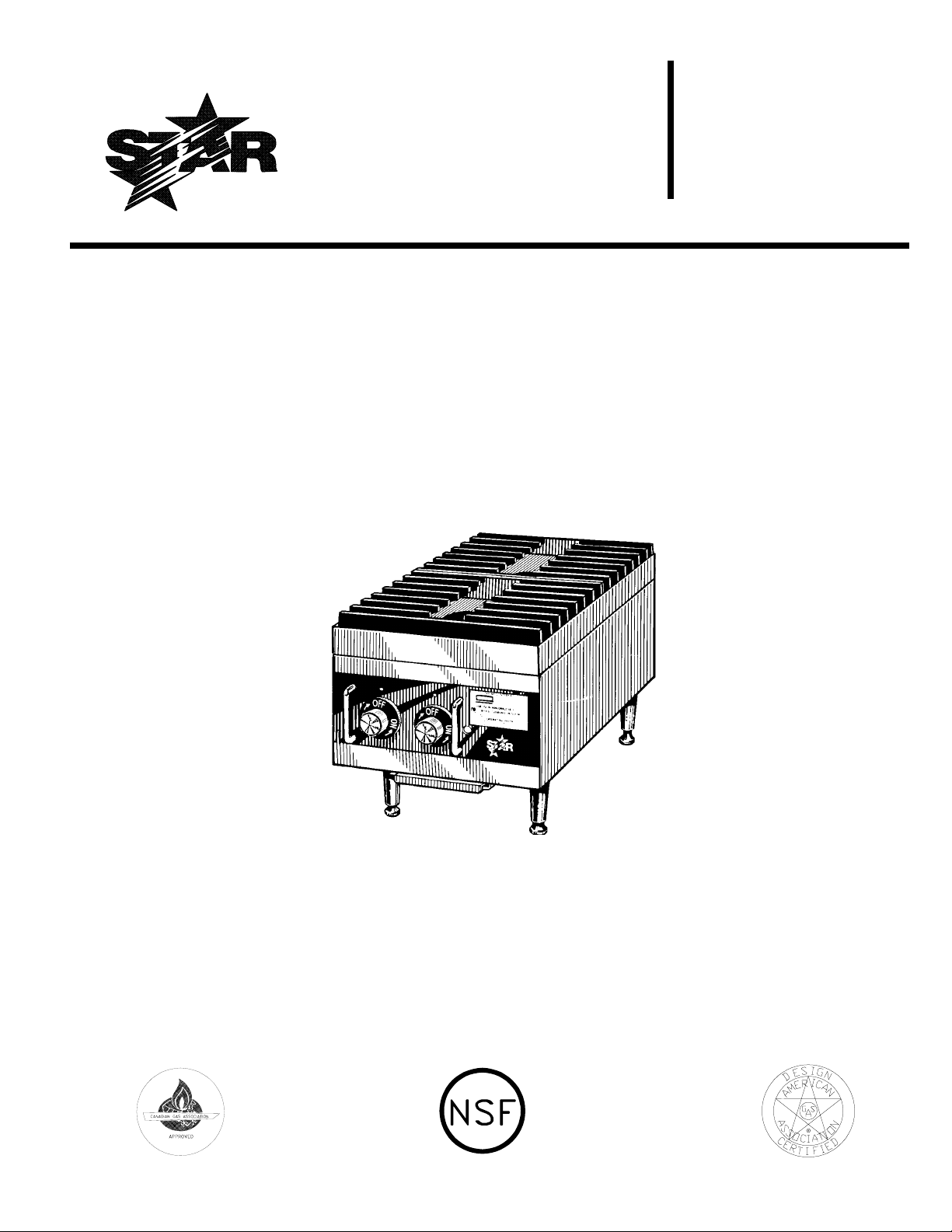
STAR-MAX GAS HOT PLATESSTAR-MAX GAS HOT PLATES
STAR-MAX GAS HOT PLATES
STAR-MAX GAS HOT PLATESSTAR-MAX GAS HOT PLATES
MODELS 602 and 602HMODELS 602 and 602H
MODELS 602 and 602H
MODELS 602 and 602HMODELS 602 and 602H
2M-Y7430 REV D 8/16/95
Installation
and
Operating
Instructions
Model 602
1
Page 2
GENERAL INSTALLATION DATA
CAUTION
This equipment is designed and sold for
commercial use only by personnel trained and
experienced in its operation and is not sold for
consumer use in and around the home nor for
use directly by the general public in food service
locations. For equipment to be used by the
general public, please contact the factory.
This gas appliance is equipped for the types of
gas indicated on the nameplate mounted on the
front panel. It is shipped adjusted for use on
natural gas.
The installation of the Appliance should
conform to the NATIONAL FUEL GAS CODE
"ANSI Z223.1 - LATEST EDITION" AND ALL
LOCAL GAS COMPANY RULES AND
REGULATIONS.
This appliance, its pressure regulator and its
individual shutoff valve must be disconnected
from the gas supply piping system during any
pressure testing of that system at test pressures
in excess of 1/2 PSIG. This appliance and its
pressure regulator must be isolated from the gas
supply piping system by closing its individual
manual shutoff valve during any pressure testing
of the gas supply piping system at test pressures
equal to or less than 1/2 PSIG. For your
protection, we recommend a qualified installing
agency install this appliance. They should be
familiar with gas installations and your local gas
requirements. In any case, your gas company
should be called to approve the final installation.
In addition, there should be posted, in a
prominent location, detailed instructions to be
followed in the event the operator smells gas.
Obtain the instructions from the local gas
supplier.
KEEP THE APPLIANCE AREA CLEAR AND
FREE FROM COMBUSTIBLES,
IN CANADA INSTALLATION SHALL BE IN
ACCORDANCE WITH THE CURRENT CAN/
CGA-B149.1 NATURAL GAS INSTALLATION
CODE OR CAN/CGA-B149.2 PROPANE
INSTALLATION CODE AND LOCAL
CODES WHERE APPLICABLE.
WARNING: Improper installation,
adjustment, alteration, service or maintenance
can cause property damage, injury or death.
Read the installation, operating and
maintenance instructions thoroughly before
installing or servicing the equipment.
FOR YOUR SAFETY
DO NOT STORE OR USE GASOLINE OR
OTHER FLAMMABLE VAPORS AND LIQUIDS
IN THE VICINITY OF THIS OR ANY OTHER
APPLIANCE. KEEP THE APPLIANCE AREA
CLEAR AND FREE FROM COMBUSTIBLES.
LEVELING UNIT
Level unit by adjusting the (4) feet which have an
adjustment of 1-3/4" for accurate and perfect lineup with other Star-Max series units. CAUTION:
DO NOT REMOVE FEET.
GAS PIPING
Gas piping shall be new, clean and of such size
and so installed as to provide a supply of gas
sufficient to meet the full gas input of the
appliance. If the appliance is to be connected to
existing piping, it shall be checked to determine if
it has adequate capacity. Joint compound (pipe
dope) shall be used sparingly and only on the
male threads of the pipe joints. Such compounds
shall be resistant to the action of L.P. gases.
WARNING: Any loose dirt or metal particles
which are allowed to enter the gas lines on the
appliance will damage the automatic valve and
affect its operation. When installing this appliance,
all pipe and fittings must be free from all internal
loose dirt.
2
Page 3

CLEARANCE
Clearances for combustible and non-combustible
materials a vertical distance of not less than 48"
shall be provided between the top of the
appliance and a 6" clearance from the side and
back. Adequate clearance should also be
provided for proper operation and servicing.
PRESSURE REGULATOR
A convertible pressure regulator set at 6" water
column for use on natural gas is furnished. Attach
the regulator to the supply pipe, located at the
back of the unit, make sure gas flow arrow on
regulator is pointing towards manifold. The gas
supply is then connected to the regulator. A 1/8"
tap is furnished on the manifold for checking
pressure. The manifold is accessible by removing
the front panel.
EXHAUST CANOPY
It is essential that facilities be provided to carry
off fumes and gases.
GAS INPUT OF HOT PLATE
For Natural Gas:
Model 602-24,000 BTU/HR or 12,000 BTU/HR
for each burner. Regulator output pressure set at
6" water column.
Model 602H-40,000 BTU/HR or 20,000 BTU/HR
for each burner. Regulator output pressure set at
6" water column.
For Propane Gas:
Model 602-24,000 BTU/HR or 12,000 BTU/HR
for each burner. Regulator output pressure set at
10" water column.
MANUAL SHUT OFF VALVE
A manual shut off valve should be installed
upstream from the union and within six feet of
the appliance
CONNECTING GAS SUPPLY LINE
The gas inlet on this appliance is sealed at the
factory to prevent entry of dirt. Do not remove
this seal until the actual connection is made to the
gas supply line.
CHECKING FOR GAS LEAKS
Soap and water solution or other material
acceptable for the purpose, shall be used in
locating gas leakage. Matches, candle flame or
other sources of ignition shall not be used for this
purpose.
AIR SUPPLY
Provisions for adequate air supply must be
furnished.
AIR INTAKES IN BOTTOM
Make certain the air intake openings in the
bottom of the appliance are not obstructed. They
are essential for proper combustion and
operation of the appliance.
Model 602H-40,000 BTU/HR or 20,000 BTU/HR
for each burner. Regulator output pressure set at
10" water column.
Note: The appliance is equipped with natural
gas orifice hoods. A separate set of hoods
(black color) are provided for use on propane
gas. The propane hoods are located on the
front panel.
LIGHTING INSTRUCTIONS
The appliance is equipped with a standing pilot,
which is located in the center of the appliance
between the front and rear burners, and should
be lighted immediately after the gas is turned on.
1. Turn control knobs to "OFF" position.
2. Remove the two top grates and light pilot with
a lighted taper through the hold provided in
the center of the top tray.
3. The pilot valve is located on the manifold
located at the front of the unit. Turn the
adjustment screw on the front of the pilot
valve, which is accessible through an opening
on the front panel. The pilot should be
adjusted to as short a flame as possible and still
have good ignition to the burners.
4. If the pilot is out turn off gas, wait 5 minutes
and repeat steps (1) through (3).
3
Page 4

ADJUSTING BURNERS
Remove front panel in order to gain access to the
primary air shutters. With control valve for the
front burner turned to full "ON" position, close
the air shutters to give a soft blue flame having
luminous tips and open to a point where the
yellow tips disappear, then tighten the locking
screws. Repeat this procedure with the rear
burner.
ADJUSTING UNIT FOR USE ON
PROPANE GAS
1. Set regulator outlet pressure to 10" water
column. A 1/8" pipe plug on the manifold can
be removed for attaching a pressure gauge.
Remove the slotted cover from the pressure
regulator and invert the plug. Replace the
cover on the regulator and plug on the
manifold. Regulator is now set at 10 inclhes
WC,
2. Remove natural gas orifices and install propane
orifices (#60 black color - model 602) and
(#55 black color - model 602H) located in a
bag located on outside of front panel. In order
to remove natural gas orifices:
A. Remove grates and top tray.
B. Remove screws on burner support in order
to lift burners out.
C. Remove orifices from the manual valves and
replace with the black propane orifices.
D.Install burners, top tray, and grates.
CLEANING THE EXTERIOR (Stainless
Steel Only)
The exterior surface can be kept clean and
attractive by regularly wiping it with a clean soft
cloth. Any discoloration can be removed with a
non-abrasive cleaner. The burner grates, drip
tray, and top tray can be removed for cleaning.
MAINTENANCE AND REPAIRS
Contact the factory or one of its representatives
or a local service company for service or
maintenance if required.
RETAIN THIS MANUAL FOR FUTURE REFERENCE
Part No. 2M-Y7430 Rev. D 8/16/95
OPERATING PROCEDURE
Each burner will deliver up to 12,000 BTU/HR
(Model 602) or 20,000 BTU/HR (Model 602H) of
heat and is controlled by a manual On/Off valve.
The right control knob controls the front burner
and the left control knob controls the rear
burner. After the pilot is once lit and adjusted,
the burners will ignite automatically by turning
the control knob to any position between On and
Off.
4
Page 5

Page 6

PARTS LIST EFFECTIVE
9-21-95 REV. C
MODEL
602, 602H Star-Max Gas Hot Plate
Number
Key
Number
1 2R-8229 2 KNOB SHIELD
2 2R-9364 2 KNOB-CONTROL
3 2R-9193 2 BUTTON-INDICATOR
5 2M-Y9489 1 FACEPLATE
6 I3-Y7407 1 FRONT PANEL
7 I3-Y7455 1 DRAWER
8 G3-Y7047 2 SLIDE DRAWER
9 2A-Y7113 4 LEG
10 2F-Z0012 2 GRATE
11 2F-Y7364 1 BURNER-FRONT
12 2F-Y7365 1 BURNER-BACK
13 I3-Y7411 1 TOP-TRAY
14 2V-Y8832 2 VALVE-MANUAL
15 2J-Y7136 1 ORIFICE #53 (NAT.) 602
15 2J-Y7216 1 BURNER HOOD (NAT.) 602H
16 2V-6671 1 VALVE-PILOT
17 2P-1453 1 PLUG-PIPE
Part
Number
Per
Unit
Description
18 2J-Y7421 2 HOOD BURNER #60 (L.P.) 602
18 2J-Y7250 2 ORIFICE #55 (L.P.) 602H
19 I3-Y7425 1 PILOT TUBE
20 2K-Y7467 1 INLET PIPE
21 2J-Y7589 1 PRESSURE REGULATOR
IMPORTANT: WHEN ORDERING, SPECIFY VOLTAGE OR TYPE GAS DESIRED PAGE
INCLUDE MODEL AND SERIAL NUMBER OF
1
1
Some items are included for illustrative purposes only and in certain instances may not be available.
Star Manufacturing International, Inc.
SK1287
 Loading...