

Page 1
GARDEN HOSE UTILITY PUMP
MODEL #
HPP360, HPP12V, 473707
FW0269
0313
SUPERSEDES
1012
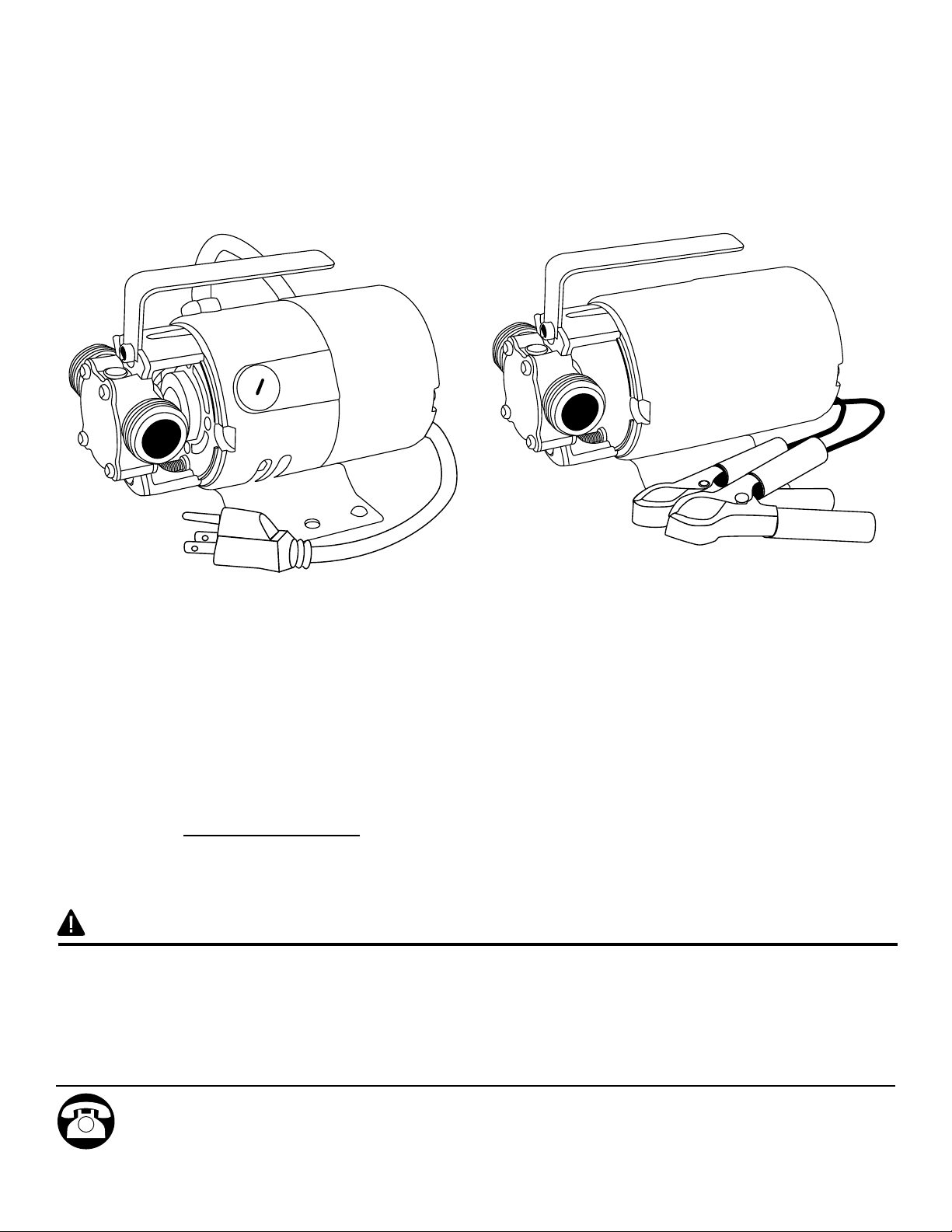
MODEL #
HPP360, 473707
MODEL #
HPP12V
ATTACH YOUR RECEIPT HERE
Purchase Date
SAFETY INFORMATION
Please read and understand this entire manual before attempting to assemble, operate or install the product.
• NOTE: Pumps with the “UL” Mark and pumps with the “US” mark are tested to UL Standard UL778. CSA
certied pumps are certied to CSA Standard C22.2 No. 108. (CUS.)
Questions, problems, missing parts? Before returning to your retailer, call our customer service
department at 1-800-724-5044.
023911 B
1
Page 2

SAFETY INFORMATION SAFETY INFORMATION
DANGER
ELECTRICAL SHOCk HAzARD.
This pump is non-submersible. Keep the motor dry at all times. Do not wash the motor. Do not immerse. Protect the
motor from wet weather. Do not allow any part of cord or receptacle ends to sit in water or in damp locations. Failure to
follow these warnings will result in death or serious injury and/or property damage.
FIRE/EXPLOSION HAzARD.
Pump only clear water. Do not pump ammable or explosive uids such as gasoline, fuel oil, kerosene, etc. Do not use
in a ammable and/or explosive atmosphere. Failure to follow these warnings could result in death or serious injury and/
or property damage.
RISk OF ELECTRIC SHOCk.
These pumps have not been investigated for use in swimming pool areas.
wARNING
ELECTRICAL SHOCk ALERT.
Before installing this product, have the electrical circuit checked by an electrician to ensure proper grounding.
ELECTRICAL SHOCk ALERT.
All wiring should be performed by a qualied electrician.
ELECTRICAL SHOCk ALERT.
Connect Models HPP360 and 473707 to a properly-grounded 115 volt circuit equipped with a Ground fault Circuit
iInterrupter (GFCI) device.
ELECTRICAL SHOCk ALERT.
Do not handle pump or pump motor with wet hands or when standing on a wet or damp surface or in water.
ELECTRICAL SHOCk ALERT.
Protect pump from extreme heat, cold and humidity. This unit is not waterproof and is not intended to be used in showers,
saunas, or other potentially wet locations. The motor is designed to be used in a clean, dry location with access to an
adequate supply of cooling air. Ambient temperature around the motor should not exceed 104°F (40°C). For outdoor
installations, motor must be protected by a cover that does not block airow to and around the motor. This unit is not
weatherproof, nor is it able to be submersed in water or any other liquid. Do not use in or near swimming pool or spa.
ELECTRICAL SHOCk ALERT.
BE CERTAIN the pump power source is disconnected before installing or servicing pump.
ELECTRICAL SHOCk ALERT.
In any installations where property damage and/or personal injury might result from an inoperative or leaking pump due to
power outages, discharge line blockage, or any other reason, a backup system(s) should be used. In order to safely use
this product, familiarize yourself with this pump.
CAUTION
PERSONAL INJURY OR PRODUCT DAMAGE MAY RESULT
Models HPP360 and 473707 operate on 115 volts. Make certain that the power source conforms to the requirements of
your equipment.
PRODUCT DAMAGE MAY RESULT
This pump is not designed to handle salt water, brine, laundry discharge or any other liquid that may contain caustic
chemicals and/or foreign materials.
PRODUCT DAMAGE MAY RESULT
The maximum temperature of the pumped liquid must not exceed 130°F (54°C). The minimum allowable temperature is
40°F (4°C).
PRODUCT DAMAGE MAY RESULT
Be sure the water source and piping are clear of sand, dirt and scale. Debris will clog the pump and void the warranty.
PRODUCT DAMAGE MAY RESULT
Failure to protect the pump and piping from freezing will cause damage and void the warranty.
PRODUCT DAMAGE MAY RESULT
Do not run pump dry. Impeller and seal damage will result.
PERSONAL INJURY MAY RESULT
Release all pressure within the system before servicing any component. Provide a means of pressure relief for
installations where the discharge line can be shut off or obstructed.
PROPERTY DAMAGE MAY RESULT
Drain all liquids from the system before servicing.
PERSONAL INJURY AND/OR PROPERTY DAMAGE MAY RESULT
Secure the discharge line before starting the pump. An unsecured discharge line will whip, possibly causingi personal
injury and/or property damage.
PERSONAL INJURY MAY RESULT
Do not touch motor while operating pump. Motor is designed to operate at high temperatures.
PACkAGE CONTENTS
Description Quantity
Pump 115V or 12V 1
Inlet Hose 1
Puddle Vac 1
ELECTRICAL SHOCk ALERT.
Protect electrical cord from sharp objects, hot surfaces, oil and chemicals. Avoid kinking the cord. Replace or repair
damaged or worn cords immediately.
PERSONAL INJURY ALERT.
Models HPP360 and 473707 are equipped with an automatic resetting thermal protector and may restart unexpectedly.
Refer to troubleshooting.
CHEMICAL ALERT.
This product contains chemicals known to the state of California to cause cancer and birth defects or other reproductive
harm.
2 3
MODEL #
HPP360 / 473707
MODEL #
HPP12V
Page 3

PREPARATION
PRIMING AND STARTUP
Before beginning installation of product, make sure all parts are present. Compare parts with package contents
list. If any part is missing or damaged, do not attempt to assemble the product.
Estimated Installation Time: 5 minutes
No tools required for assembly.
INSTALLATION INSTRUCTIONS
NOTE: Pump depends on the liquid owing through it for
lubrication. DO NOT RUN THE PUMP DRY!
1. Mount pump solidly on a stable platform. Pump should
be located so that the water source is within reach of
supplied 6 ft. inlet hose.
2. Check the washer in the inlet tting of pump to make sure
it is air tight. If this leaks, pump will not operate. Install inlet
hose on the inlet side of pump. Make sure all connections
are tight.
Install a 5/8 in. outlet hose (not included) on the outlet
side of pump. Outlet hose should be as short as possible
and no longer than 25 ft. The inlet hose must reach below
the surface of the water and the outlet hose must be kept
above water.
1
Outlet Inlet
2
Outlet Hose
3 ft. Max.
Vertical
Water Source
4a. For models HPP360 and 473707, plug the cord into a
3-wire, 115 volt, 60Hz grounded A/C outlet protected by
a ground-fault circuit-interruptor. Pump will deliver 350
gallons per hour with an unrestricted discharge line. If the
discharge line is restricted or raised, pump will pump less
water.
4b. For model HPP12V, attach red battery clip to positive
terminal and black battery clip to negative terminal of a
fully charged battery.
5. To reduce friction, do not coil or kink the hoses. When
pumping from a well or stream, raise the inlet hose a few
inches off the bottom to avoid pumping in debris which
can damage the pump.
4a
Discharge
Water
4b
5
Discharge
Water
Outlet Hose
Red
Battery
Clip
Water
Source
Outlet Hose
Positive
Terminal
Water
Source
Black Battery
Clip
Negative
Terminal
Battery
PRIMING AND STARTUP
3. To prime pump, ll the pump cavity through inlet to wet
impeller. Connect supplied 6 ft. inlet hose and submerge
below surface of water. Turn on pump.
4 5
3
Outlet
Inlet
Outlet Inlet
Water Source
6. This unit is shipped with a puddle vac accessory which
allows it to remove water from at surfaces. After
attaching inlet hose in step 2, screw the puddle vac onto
the end of the inlet hose and place it on the surface to be
pumped.
CAUTION: Before water is completely gone, unplug the
pump. DO NOT RUN PUMP DRY!
Water
Source
6
Page 4

INSTALLATION INSTRUCTIONS
CARE AND MAINTENANCE
7. If pump does not start to pump water within 30 seconds,
unplug and re-check the installation and plumbing as
follows.
- Check to be sure pump is located so that the water
source is within reach of supplied 6 ft. inlet hose.
- Check to be sure all inlet connections are air and water-
tight and inlet hose is as short as possible.
- Check to be sure inlet hose is below the surface of the
water source.
- Check to be sure the outlet hose is less than 25 ft. in
length and is above the surface of the outlet water.
CARE AND MAINTENANCE
1. Always drain pump when not in use. If pump is going to be
out of use for a month or longer, ush with fresh water and
remove face plate cover. Remove impeller, clean inside
pump cavity and apply a generous coating of petroleum jelly
(not included) to the inside of the cavity and the impeller
before replacing the impeller. The pump should be checked
frequently for proper operation. If anything has changed
since the pump was new, it should be repaired or replaced.
CAUTION: Only qualied electricians should repair this unit.
Improper repair and/or assembly can cause electrical shock
hazard.
2. How to Replace Brushes (115V pump only)
NOTE: Motor brushes (not included) are normal wear items and
must be replaced periodically.
- Be sure pump is disconnected from power source.
- Unscrew brush cap located along the side of the motor.
Remove brush and spring and spring cover by pulling them
straight out of the brush holder.
- Install new brush and spring assembly (not included), keeping
the new brush curvature aligned the same as the previous
brush.
- Replace cap.
7
Outlet Inlet
1
2
Spring
Brush
Cap
Water Source
Spring
Brush
Cap
Brush
Cap
3 ft. Max.
Vertical
3. How to Replace Impeller
NOTE: Replace the impeller when it has been worn or
damaged by foreign objects, improper liquid or running dry.
- Remove four face plate screws, face plate and gasket.
- Remove damaged or worn impeller.
- Clean the inside of the pump cavity and remove any foreign
materials that might prevent the impeller from moving easily.
- Apply petroleum jelly to the inside of the pump cavity and the
outside of the new impeller (not included).
- Align the at on the new impeller with the at on the motor
shaft. Push into place while twisting blades in a clockwise
direction.
- Place new gasket on pump cavity face, align holes and
replace cover. Tighten all four screws evenly and snugly.
3
Face Plate
Screws (4)
Pump Cavity
Impeller
Gasket
Face Plate
TROUBLESHOOTING
Problem Possible Cause Corrective Action
Pump will not
prime or retain
prime after
operating.
1. Pump won’t prime. 1. See priming instructions on page 6.
2. Suction lift too high. 2. Move pump closer to water source.
3. Hose kinked. 3. Straighten hose.
4. Hose fitting not tight on inlet. 4. Tighten fitting.
5. Air leak in suction hose. 5. Repair or replace hose.
Pump runs
but no water is
discharged.
1. Hose kinked. 1. Straighten hose.
2. Pump is not primed. 2. See priming instructions on page 6.
3. Defective impeller. 3. Replace impeller.
4. Suction lift too high. 4. Move pump closer to water source.
5. Discharge height too great. 5. Reduce discharge height.
6. Clogged inlet. 6. Clean inlet.
Motor runs too
hot.
1. Voltage incorrect. 1. Connect to 115 volt outlet.
2. Restricted discharge hose. 2. Increase hose diameter to 3/4 in.
3. Impeller damaged. 3. Replace impeller.
4. Liquid too viscous. 4. Reduce viscosity of liquid.
5. Plugged or kinked discharge. 5. Clean and straighten hose.
6. Insufficient air flow on motor. 6. Make sure ample fresh air is available
at the motor.
Flow rate is low. 1. Hose kinked. 1. Straighten hose.
2. Clogged impeller. 2. Clear obstruction.
3. Worn impeller. 3. Replace impeller.
4. Excessive length of hose. 4. Reduce length of inlet and outlet hose.
Pump will not
run.
1. No power. 1. Verify that unit is plugged into 115 volt
outlet.
2. Impeller jammed. 2. Clean pump cavity and impeller.
3. Motor overheated. 3. Motor has automatic thermal protector.
Wait fifteen minutes for motor to cool.
6 7
Page 5

REPLACEMENT PARTS
KH71
KH72 (set of 2)
Brush
Assembly
Impeller
Gasket
Part # Description
KH71 Gasket & impeller kit for HPP360, 473707 & HPP12V
KH72 Brush kit for HPP360, 473707
023754 Pump Head Kit (Includes face plate, seal, impeller and pump head)
LIMITED wARRANTY
This product is warranted for one year from the date of
purchase or two years from the date of manufacture,
whichever occurs rst. Subject to the conditions hereinafter
set forth, the manufacturer will repair or replace to the
original consumer, any portion of the product which proves
defective due to defective materials or workmanship. To
obtain warranty service, contact the dealer from whom the
product was purchased. The manufacturer retains the sole
right and option to determine whether to repair or replace
defective equipment, parts or components. Damage due
to conditions beyond the control of the manufacturer is not
covered by this warranty.
THIS WARRANTY WILL NOT APPLY: (a) To defects
or malfunctions resulting from failure to properly install,
operate or maintain the unit in accordance with printed
instructions provided; (b) to failures resulting from abuse,
accident or negligence or use of inappropriate chemicals or
additives in the water; (c) to normal maintenance services
and the parts used in connection with such service;
(d) to units which are not installed in accordance with
normal applicable local codes, ordinances and good trade
practices; and (e) the unit is used for purposes other than
for what it was designed and manufactured.
Brush
Assembly
THE WARRANTY PROVIDED HEREIN IS IN LIEU OF ALL
OTHER EXPRESS WARRANTIES, AND MAY NOT BE
EXTENDED OR MODIFIED BY ANYONE. ANY IMPLIED
WARRANTIES SHALL BE LIMITED TO THE PERIOD
OF THE LIMITED WARRANTY AND THEREAFTER ALL
SUCH IMPLIED WARRANTIES ARE DISCLAIMED AND
EXCLUDED. THE MANUFACTURER SHALL NOT, UNDER
ANY CIRCUMSTANCES, BE LIABLE FOR INCIDENTAL,
CONSEQUENTIAL OR SPECIAL DAMAGES, SUCH
AS, BUT NOT LIMITED TO DAMAGE TO, OR LOSS
OF, OTHER PROPERTY OR EQUIPMENT, LOSS OF
PROFITS, INCONVENIENCE , OR OTHER INCIDENTAL
OR CONSEQUENTIAL DAMAGES OF ANY TYPE OR
NATURE. THE LIABILITY OF THE MANUFACTURER
SHALL NOT EXCEED THE PRICE OF THE PRODUCT
UPON WHICH SUCH LIABILITY IS BASED.
This warranty gives you specic legal rights, and you may
have other rights which vary from state to state. Some
states do not allow limitations on duration of implied
warranties or exclusion of incidental or consequential
damages, so the above limitations may not apply to you.
WARRANTY VALID IN CANADA AND MEXICO.
RETURN OF WARRANTED COMPONENTS: Any item
to be repaired or replaced under this warranty must be
returned to the manufacturer at Kendallville, Indiana or
such other place as the manufacturer may designate,
freight prepaid.
8
 Loading...