

Page 1
Notice to Installer: Instructions must remain with installation.
INSTALLATION INSTRUCTIONS
FW1088
0611
Supersedes
1108
PUMP PERFORMANCE
Vertical Lift (Ft.) Gal.
MODELS 3CEH, 433063
5 50
10 36
15 10
Shut off Head 16 Ft.
PREINSTALLATION CHECKLIST - ALL INSTALLATIONS
1. Inspect your pump. Occasionally, products are damaged during shipment. If the unit is damaged, contact your dealer
before using.
2. Carefully read the literature provided to familiarize yourself with specific details regarding installation and use. These
materials should be retained for future reference.
SEE BELOW FOR LIST OF WARNINGS
1. Make sure there is a properly installed ground
fault circuit interrupter (GFCI) protected circuit available. All
pumps are furnished with provisions for proper grounding to
help protect you against the possibility of electrical shock.
2. Make certain that the ground fault receptacle
is within the reach of the pump’s power supply cord DO
NOT USE AN EXTENSION CORD. Extension cords that
are too long or too light do not deliver sufficient voltage to
the pump motor. But, more important, they could present a
safety hazard if the insulation were to become damaged or
the connection ends were to fall into the sump and become
wet.
3. Make sure the pump electrical supply circuit is equipped with fuses or circuit breakers of proper
capacity. A separate branch circuit is recommended, sized
according the National Electrical Code for the current shown
on the pump name plate.
4. TESTING FOR GROUND. As a safety measure,
each electrical outlet should be checked for ground using
an Underwriters Laboratory Listed circuit analyzer which will
indicate if the power, neutral and ground wires are correctly
connected to your outlet. If they are not, call a qualified
licensed electrician.
5. Installation and checking of electrical circuits
and hardware should only be performed by a qualified licensed
electrician.
6. FOR YOUR PROTECTION, ALWAYS DIS-
CONNECT PUMP FROM ITS POWER SOURCE BEFORE
HANDLING.
7. These pumps are supplied with a 3-prong
grounded plug to help protect you against the possibility of
electrical shock. DO NOT UNDER ANY CIRCUMSTANCES
REMOVE THE GROUND PIN. The 3-prong plug must be
inserted in a mating 3-prong fault interrupter receptacle. If
the installation does not have such a receptacle, it must be
changed to the proper type, wired, and grounded in accordance with the National Electrical Code and all applicable
local codes and ordinances.
SEE BELOW FOR LIST OF WARNINGS (CONTINUED)
8. RISK OF ELECTRIC SHOCK. These pumps
have not been investigated for use in swimming pool areas.
9.
the State of California to cause cancer and birth defects
or other reproductive harm.
1. Check to be sure your power source is ca-
pable of handling the voltage requirements of the motor,
as indicated on the pump name plate.
2. The installation of automatic pumps with
auxiliary float switches is the responsibility of the installing
party and care should be taken that the tethered float
switch will not hang up on the pumping apparatus or pit
peculiarities and is secured so that the pump will shut off.
It is recommended to use rigid piping and fittings and the
pit be 12" or larger in diameter.
3. These pumps are not designed or intended
to be used to handle sewage or effluent.
4. Maximum continuous operating water temperature for standard model pumps must not exceed 77°F
(25°C).
5. This pump has been evaluated for use with
WATER only.
NOTE: A BATTERY BACKUP SYSTEM IS RECOMMENDED
TO PREVENT FLOODING AND/OR PROPERTY DAMAGE
IN THE EVENT OF MECHANICAL MALFUNCTION OR
POWER OUTAGE.
NOTE: Pumps with the “CSA” mark are tested to UL
standard UL778 and certified to CSA standard C22.2 No.
108.
This product contains chemicals known to
SEE BELOW FOR LIST OF CAUTIONS
DO NOT USE FOR PUMPING OILS, GASOLINE OR ANY PETROLEUM BY-PRODUCTS.
95 N. Oak St. • Kendallville, IN 46755 • 1-800-345-9422
1
© 2011. All rights reserved.
Page 2
LIMITED WARRANTY
This product is warranted for one year from the date of purchase or two years from
the date of manufacture, whichever occurs first. Subject to the conditions hereinafter
set forth, the manufacturer will repair or replace to the original consumer, any portion
of the product which proves defective due to defective materials or workmanship. To
obtain warranty service, contact the dealer from whom the product was purchased.
The manufacturer retains the sole right and option to determine whether to repair or
replace defective equipment, parts or components. Damage due to conditions beyond
the control of the manufacturer is not covered by this warranty.
THIS WARRANTY WILL NOT APPLY: (a) To defects or malfunctions resulting from
failure to properly install, operate or maintain the unit in accordance with printed
instructions provided; (b) to failures resulting from abuse, accident or negligence or
use of inappropriate chemicals or additives in the water; (c) to normal maintenance
services and the parts used in connection with such ser vice; (d) to units which are
not installed in accordance with normal applicable local codes, ordinances and
good trade practices; and (e) the unit is used for pur poses other than for what it was
designed and manufactured.
RETURN OF WARRANTED COMPONENTS: Any item to be repaired or replaced
under this warranty must be returned to the manufacturer at Kendallville, Indiana or
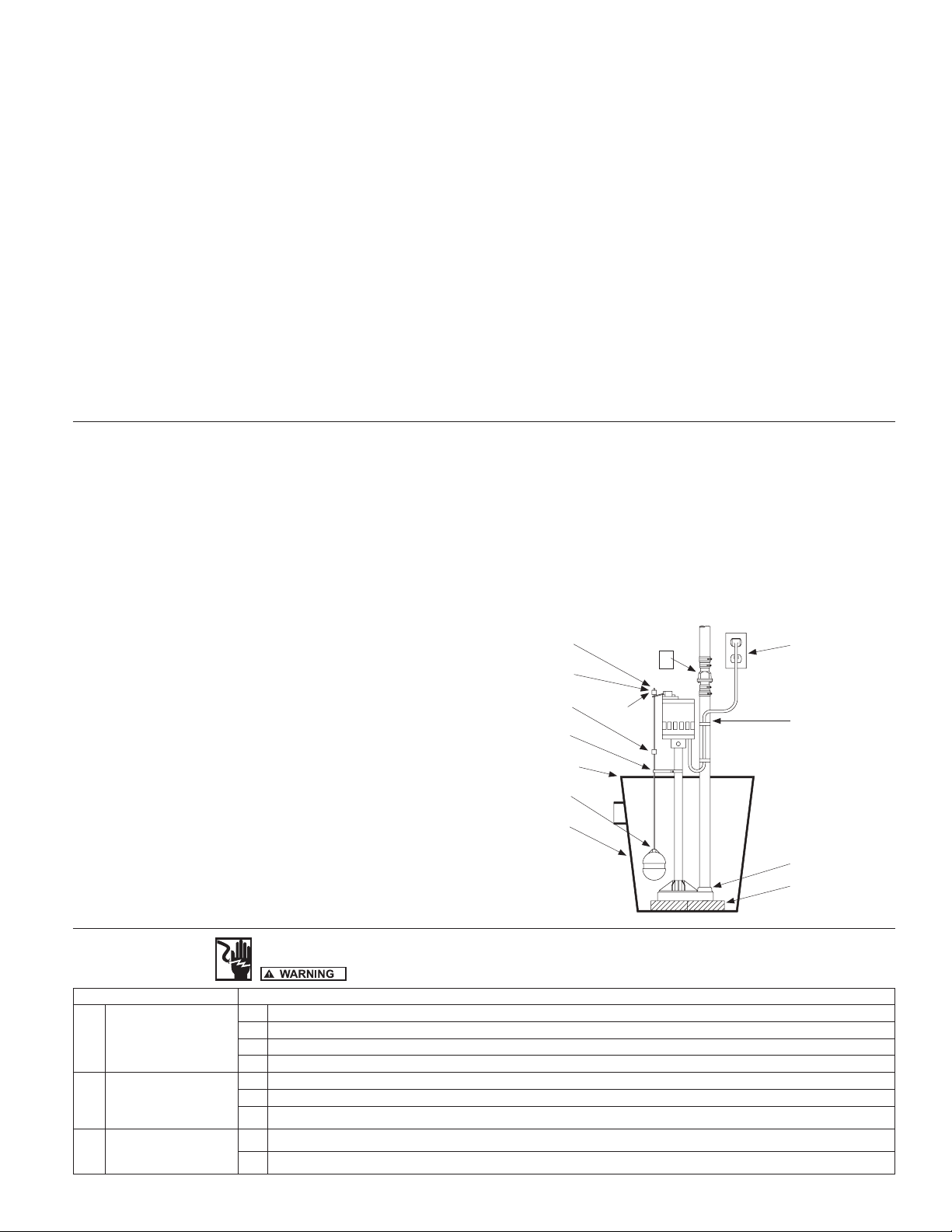
TYPICAL COLUMN SUMP PUMP INSTALLATION
such other place as the manufacturer may designate, freight prepaid.
THE WARRANTY PROVIDED HEREIN IS IN LIEU OF ALL OTHER EXPRESS
WARRANTIES, AND MAY NOT BE EXTENDED OR MODIFIED BY ANYONE. ANY
IMPLIED WARRANTIES SHALL BE LIMITED TO THE PERIOD OF THE LIMITED
WARRANTY AND THEREAFTER ALL SUCH IMPLIED WARRANTIES ARE
DISCLAIMED AND EXCLUDED. THE MANUFACTURER SHALL NOT, UNDER
ANY CIRCUMSTANCES, BE LIABLE FOR INCIDENTAL, CONSEQUENTIAL OR
SPECIAL DAMAGES, SUCH AS, BUT NOT LIMITED TO DAMAGE TO, OR LOSS
OF, OTHER PROPERTY OR EQUIPMENT, LOSS OF PROFITS, INCONVENIENCE
, OR OTHER INCIDENTAL OR CONSEQUENTIAL DAMAGES OF ANY TYPE OR
NATURE. THE LIABILITY OF THE MANUFACTURER SHALL NOT EXCEED THE
PRICE OF THE PRODUCT UPON WHICH SUCH LIABILITY IS BASED.
This warranty gives you specific legal rights, and you may have other rights which
vary from state to state. Some states do not allow limitations on duration of implied
warranties or exclusion of incidental or consequential damages, so the above
limitations may not apply to you.
WARRANTY VALID IN CANADA AND MEXICO.
1. Electrical wiring must be in accordance with the National Electrical Code
and all other applicable state and local electrical requirements.
2. Install combination check valve and union preferably just above the sump
pit to allow easy removal of the pump for cleaning or repair.
3. Minimum pit size recommended is 18” diameter and 22” deep.
4. Locate float rod guide locator hole about midpoint of the column. Snap
float rod guide on to column at this location making sure that the nub on
the guide snaps into the hole.
5. Unscrew float from the float rod. Insert threaded end of float rod down
through eye of rod guide and screw float full back on the float rod.
6. Remove top rubber stop from float rod.
7. Pass rod through eye of pump switch.
8. Slide top rubber rod stop back onto the float rod flush with top after
passing through eye of switch. WARNING: Risk of flooding. Be sure that
float rod is vertical and can move up and down freely. If float is angled or
binds, pump may not start, allowing flooding to occur.
9. If the lower rod stop is positioned approximately 8” from the top of the rod,
the pump will automatically cycle on at a water level about 10 -12” and off
approximately. For faster cycling, move lower rod stop closer to switch
lever arm.
10. Thread pipe in discharge of pump. Use care not to cross thread or strip the
threads. Use a full-size discharge pipe.
11. Clean basin free of debris after installation.
12. Install blocks or bricks under pump to provide a settling basin.
13. Place pump in center of sump pit.
14. Securely tape or clamp power cord to discharge pipe clear of float
mechanism.
15. Check for proper ON-OFF switch operation by running water into the sump
pit.
16. All installations require a proper basin cover to prevent debris from falling
into the basin and to minimize accidental injury.
CAUTION:
CHECK ROD AND FLOAT FOR FREE SWITCH OPERATION
TO ENSURE THAT PUMP WILL TURN ON AND OFF.
6
7
9
4
16
5
3
2
8
13
11
1
14
10
12
IL0726
SERVICE CHECKLIST TROUBLESHOOTING CHART
UNPLUG PUMP BEFORE HANDLING PUMP OR PIPING
CONDITION COMMON CAUSES
A. Unit will not start 1. Check circuit protection.
2. Check electrical current supply to make sure it is the same as on the pump specification plate
3. Check rod and float for free ON-OFF switch operation. Readjust rod stops or guide if necessary
4. Check ON-OFF switch operation by running water into basin
B. Unit starts or sounds
like it is running but will
not pump
C. Unit stops and starts
excessively
1. Clear intake and discharge. Run to test operation.
2. Check to see that vertical lift of installation is within pump capacity. (Refer to pump capacity chart on page 1).
3. Check impeller for proper rotation. (Clockwise when viewed from motor end).
1. Install a proper check valve to prevent back flow from piping.
2. Check dimensions of basin as listed on previous page, Item 3.
2
© 2011. All rights reserved.
 Loading...