

Page 1
HYBRID PRINTER
HSP7000 SERIES
Hardware Manual
Page 2

Federal Communications Commission
Radio Frequency Interference
This device complies with Part 15 of the FCC Rules. Operation is subject to the following two conditions: (1) This device may not cause harmful interference, and (2) this device must
accept any interference received, including interference that may cause undesired operation.
NOTE: This equipment has been tested and found to comply with the limits for a Class B digital device, pursuant to Part 15 of FCC rules. These limits are designed to provide
reasonable protection against harmful interference in a residential installation. This equipment generates, uses and can radiate radio frequency energy and, if not installed and
used in accordance with the instructions, may cause harmful interference to radio communications. However, there is no guarantee that interference will not occur in a particular
installation. If this equipment does cause harmful interference to radio or television reception, which can be determined by turning the equipment off and on, the user is encouraged
to try to correct the interference by one or more of the following measures.
• Reorient or relocate the receiving antenna.
• Increase the separation between the equipment and receiver.
• Connect the equipment into an outlet on a circuit different from that to which the receiver is connected.
• Consult the dealer or an experienced radio/TV technician for help.
This statement will be applied only for the printers marketed in U.S.A.
FCC WARNING
Changes or modications not expressly approved by the party responsible for compliance could void the user’s authority to operate the equipment.
For compliance with the Federal Noise Interference Standard, this equipment requires a shielded cable.
For RF interference suppression, if a ferrite core is provided with this device, afx it to the interface cable.
Statement
The Canadian Department of Communications
Radio Interference Regulations
This Class B digital apparatus complies with Canadian ICES-003.
Cet appareil numérique de la classe B est conforme à la norme NMB-003 du Canada.
The above statement applies only to printers marketed in Canada.
Statement of
Trademark acknowledgments
HSP7000
: Star Micronics Co., Ltd.
Notice
• All rights reserved. Reproduction of any part of this manual in any form whatsoever, without
STAR’ s express permission is forbidden.
• The contents of this manual are subject to change without notice.
• All eorts have been made to ensure the accuracy of the contents of this manual at the time of
going to press. However, should any errors be detected, STAR would greatly appreciate being
informed of them.
• The above notwithstanding, STAR can assume no responsibility for any errors in this manual.
© Copyright 2008-2011 Star Micronics Co., Ltd.
Page 3

TABLE OF CONTENTS
1. Unpacking and Installation .....................................................................................................................1
1-1. Unpacking ....................................................................................................................................1
1-2. Choosing a place for the printer ...................................................................................................2
1-3. Removing the protective materials ..............................................................................................3
2. Parts Identication and Nomenclature ..................................................................................................4
3. Setup ..........................................................................................................................................................5
3-1. Connecting the Interface Cable to the PC ....................................................................................5
3-2. Connecting the Interface Cable to the Printer ..............................................................................7
3-3. Installing the Printer Software ...................................................................................................11
3-4. Connecting the Optional AC Adapter ........................................................................................12
3-5. Turning Power On ......................................................................................................................13
3-6. Switch Cover Installation ...........................................................................................................14
3-7. Connecting to a Peripheral Unit .................................................................................................15
3-8. Attaching the Interface Cover ....................................................................................................16
4. Loading the Ribbon Cartridge and Paper ...........................................................................................17
4-1. Loading the Ribbon Cartridge ...................................................................................................17
4-2. Loading the Paper Roll ..............................................................................................................18
4-3. Loading the Slip Paper or Validation Paper ...............................................................................20
4-4. Scanning MICR Characters .......................................................................................................21
5. Consumable Parts and AC Adapter .....................................................................................................24
5-1. Thermal Paper Roll ....................................................................................................................24
5-2. Slip Paper ...................................................................................................................................26
5-3. AC adapter (option) ...................................................................................................................27
6. Control Panel and Other Functions .....................................................................................................28
6-1. Control Panel .............................................................................................................................28
6-2. Errors ..........................................................................................................................................29
6-3. Self-Printing ...............................................................................................................................31
6-4. Cleaning Mode ...........................................................................................................................35
6-5. Sensor Adjustment .....................................................................................................................35
7. Adjusting the Near-end Sensor .............................................................................................................41
8. Preventing and Clearing Paper Jams ...................................................................................................43
8-1. Preventing Paper Jams ...............................................................................................................43
8-2. Removing Paper Jam .................................................................................................................43
8-3. Releasing a Locked Cutter .........................................................................................................45
9. Maintenance ...........................................................................................................................................46
9-1. Thermal Printer ..........................................................................................................................46
9-2. Slip Printer .................................................................................................................................47
9-3. MICR Head ................................................................................................................................47
9-4. Cleaning the Sensors and the Surrounding Area ........................................................................48
9-5. Cleaning the Paper Holder and the Surrounding Area ...............................................................48
Page 4

10. Specications ........................................................................................................................................49
10-1. General Specications ...............................................................................................................49
10-2. Auto Cutter Specications .........................................................................................................50
10-3. MICR Specications ..................................................................................................................50
10-4. External Specications ...............................................................................................................51
10-5. Interface Specications ..............................................................................................................52
10-6. Power Specs ...............................................................................................................................53
10-7. Environmental Requirements .....................................................................................................54
10-8. Reliability Specications ...........................................................................................................55
11. Dip Switch Setting ................................................................................................................................57
11-1. Parallel Interface Model .............................................................................................................58
11-2. RS-232C Interface Model ..........................................................................................................59
11-3. USB/PoweredUSB Interface Model ..........................................................................................61
11-4. Ethernet Interface Model ...........................................................................................................62
12. Parallel Interface ..................................................................................................................................64
13. RS-232C Serial Interface .....................................................................................................................65
13-1. Interface Specications ..............................................................................................................65
13-2. RS-232C Connector ...................................................................................................................66
13-3. Cable Connections .....................................................................................................................67
14. USB/PoweredUSB and Ethernet ........................................................................................................68
14-1. USB/PoweredUSB Interface Specications ..............................................................................68
14-2. Ethernet Interface Specications................................................................................................68
15. Peripheral Unit Drive Circuit .............................................................................................................69
16. Memory Switch Settings ......................................................................................................................71
Please access the following URL
http://www.star-m.jp/eng/dl/dl02.htm
for the latest revision of the manual.
Page 5
1. Unpacking and Installation
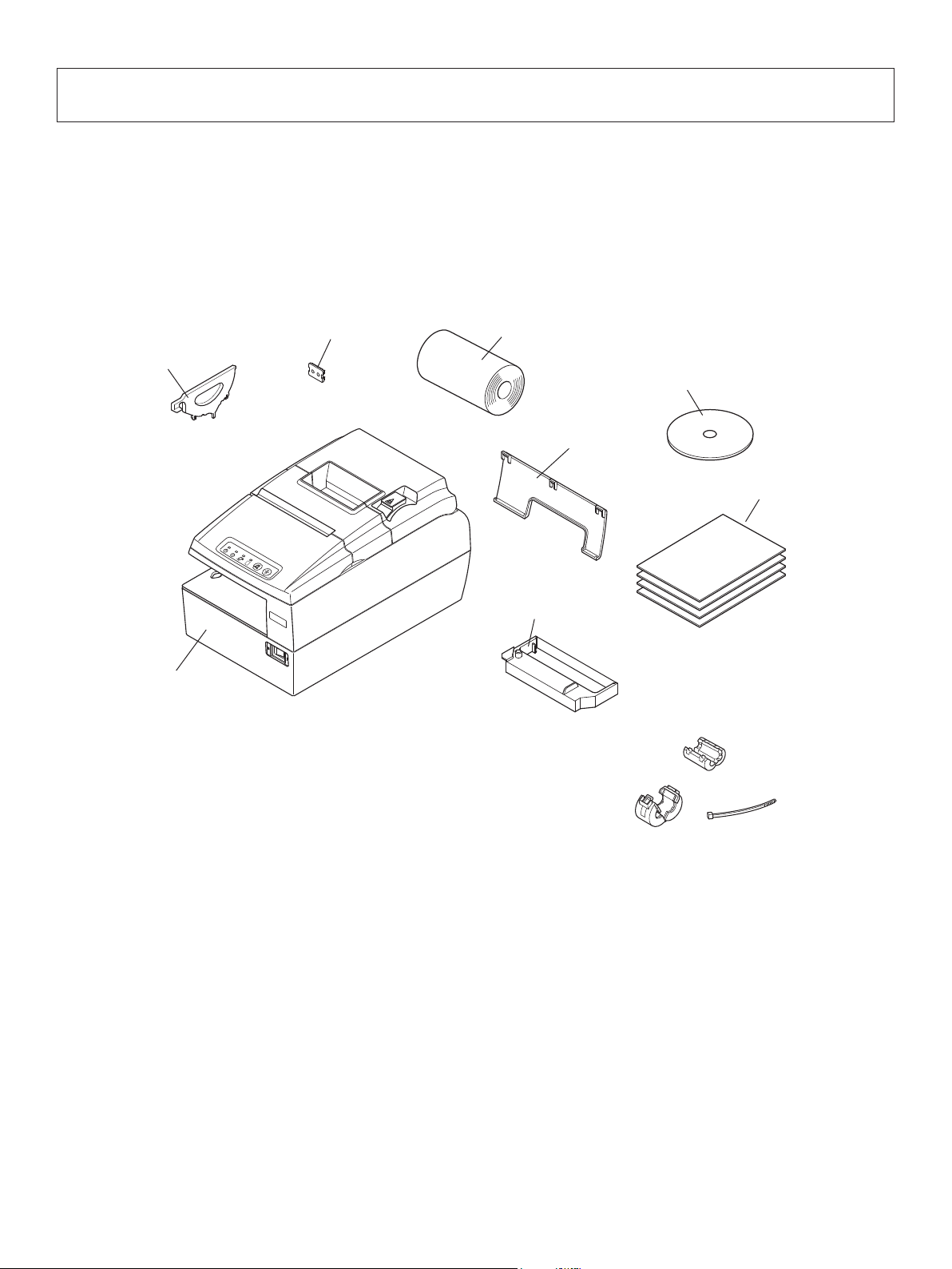
1-1. Unpacking
After unpacking the unit, check that all the necessary accessories are included in the package.
Paper guide
Printer
Switch blind
Thermal paper roll
CD-ROM
Interface cover
Setup sheets
POWER
ERROR
PAPER OUT
SLIP
FEED
RELEASE
Ribbon cassette
Note
Note: The ferrite core and fastener provided with your
printer depend on your printer conguration.
Fig. 1-1 Unpacking
If anything is missing, contact the dealer where you bought the printer and ask them to supply
the missing part. Note that it is a good idea to keep the original box and all the packing materials
just in case you need to pack the printer up again and send it somewhere at a later date.
– 1 –
Page 6

1-2. Choosing a place for the printer
Before actually unpacking the printer, you should take a few minutes to think about where
you plan to use it. Remember the following points when doing this.
P Choose a rm, level surface where the printer will not be exposed to vibration.
P The power outlet you plan to connect to for power should be nearby and unobstructed.
P Make sure that the printer is close enough to your host computer for you to connect
the two.
P Make sure that the printer is not exposed to direct sunlight.
P Make sure that the printer is well away from heaters and other sources of extreme heat.
P Make sure that the surrounding area is clean, dry, and free of dust.
P Make sure that the printer is connected to a reliable power outlet. It should not be on
the same electric circuit as copiers, refrigerators, or other appliances that cause power
spikes.
P Make sure that the room where you are using the printer is not too humid.
P This device employs a DC motor and switches that have an electrical contact point.
Avoid using the device in environments where silicon gas can become volatile.
PWhen disposing of the printer, obey local regulations.
WARNING
P Shut down your equipment immediately if it produces smoke, a strange odor, or unu-
sual noise. Immediately unplug the equipment and contact your dealer for advice.
P Never attempt to repair this product yourself. Improper repair work can be dangerous.
P Never disassemble or modify this product. Tampering with this product may result in
injury, re, or electric shock.
– 2 –
Page 7
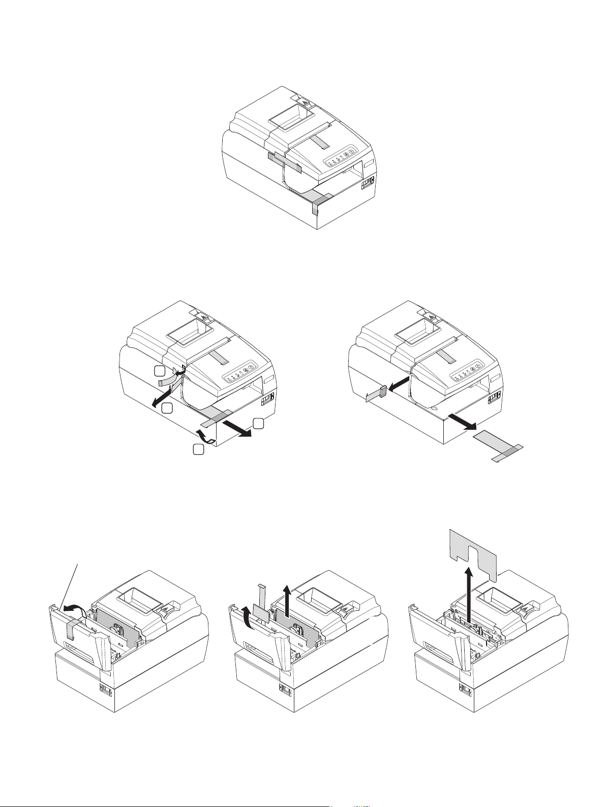
1-3. Removing the protective materials
Four protective materials are inserted into the printer to protect components during shipping.
RELEASE
FEED
SLIP
PAPER OUT
ERROR
POWER
Before using the printer, be sure to remove all protective materials as shown in the illustration.
(1) Remove the three tapes and pull the two protective sheets.
RELEASE
FEED
1
SLIP
PAPER OUT
ERROR
POWER
RELEASE
FEED
SLIP
PAPER OUT
ERROR
POWER
2
2
1
(2) Open the front cover.
Remove the tape on the front cover, and then remove the sheet.
Next, pull the protective sheet that is securing the head straight out of the unit.
Front cover
Note: That it is a good idea to keep all protective materials in case you will need to pack
the printer up again and send it somewhere at a later date.
– 3 –
Page 8
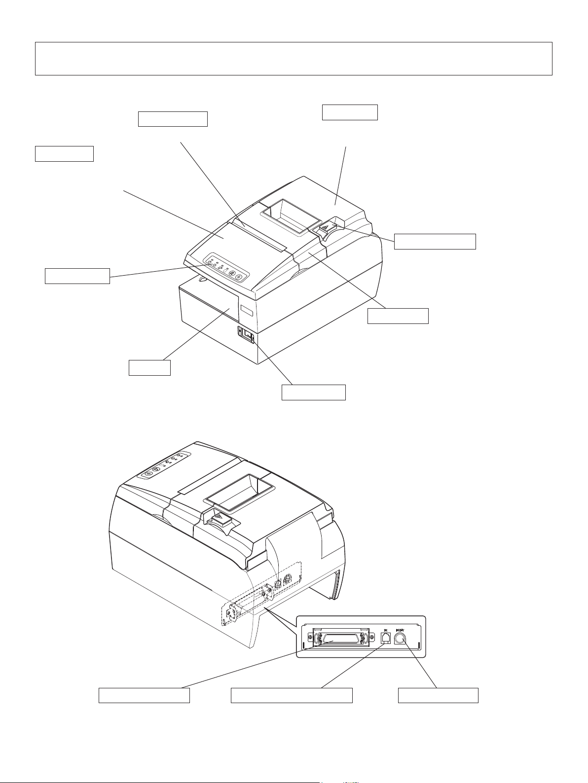
2. Parts Identication and Nomenclature
Validation slot
Insert paper here.
Front cover
Open it to replace the ribbon.
Do not open it during printing.
Control panel
Features LED indicators
to indicate printer status
and switches to operate
the printer.
Slip slot
Insert paper here.
Rear cover
Open it to replace the roll paper.
Do not open it during printing.
Cover open lever
POWER
ERROR
PAPER OUT
SLIP
FEED
RELEASE
Push this lever in the direction of the
arrow to open the rear cover.
Cutter cover
Open it to clear paper jam.
Do not open it during printing.
Power switch
PAPER OUT
SLIP
FEED
RELEASE
Interface connector
Used to turn on/off
power to the printer.
POWER
ERROR
Peripheral drive connector
Power connector
For connection to a
host computer.
Connects to peripheral units such
as cash drawers, etc.
Do not connect this to a telephone.
– 4 –
For connection of the AC adapter.
Never unplug the AC adapter while
the printer is on.
Page 9
3. Setup
3-1. Connecting the Interface Cable to the PC
CAUTION
The optional USB, PoweredUSB, and LAN cables have been designed specically for this unit
(HSP7000).
Other USB, PoweredUSB, and LAN cables may not meet the EMC technical standards.
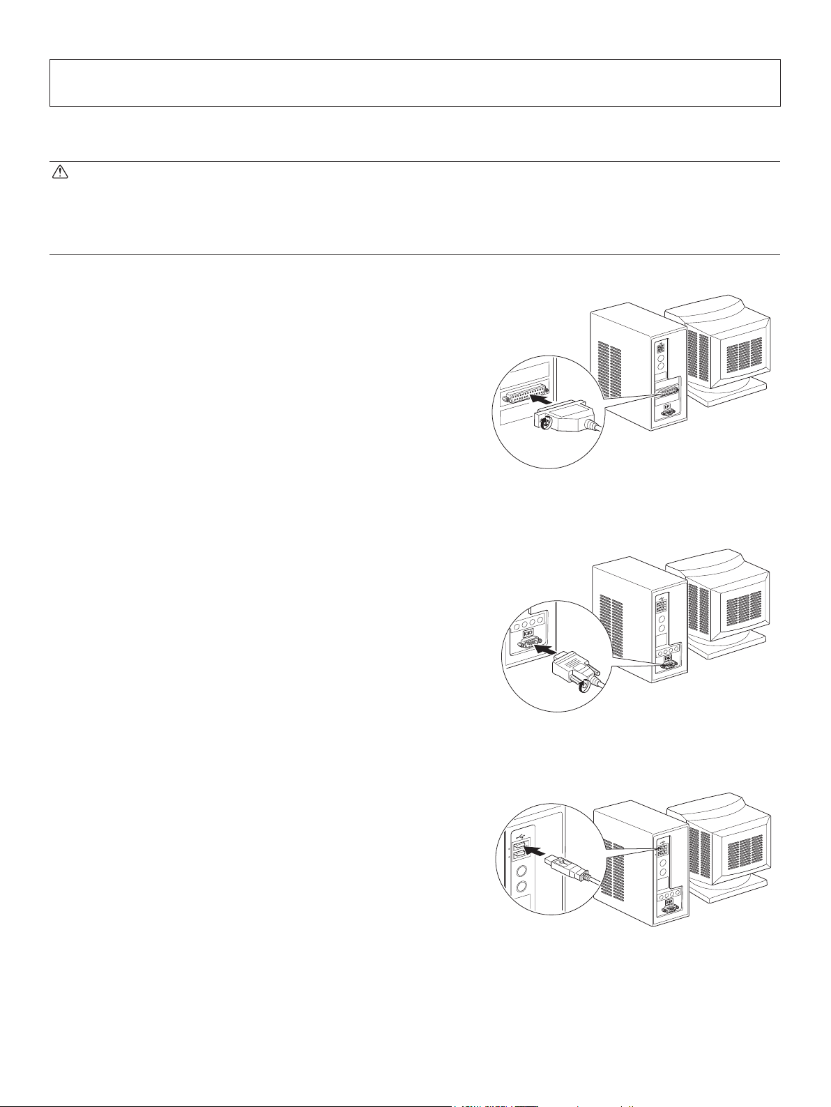
3-1-1. Parallel Interface Cable
Connect the parallel interface cable to a parallel port
of your PC.
3-1-2. RS-232C Interface Cable
Connect the RS-232C interface cable to a RS-232C
port of your PC.
3-1-3. USB Interface Cable
Connect the USB interface cable to a USB port of
your PC.
Option: USB cable 1.8M TSP1 (P/N: 30729100)
– 5 –
Page 10
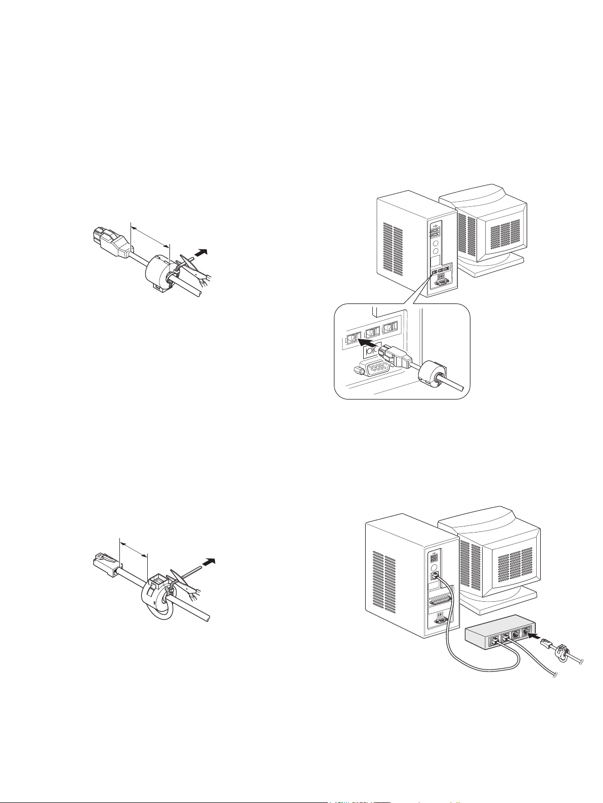
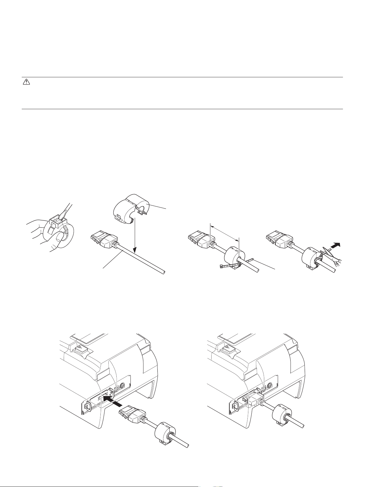
3-1-4. PoweredUSB Interface Cable
Attach the ferrite core to the PoweredUSB interface cable, and connect the cable to a PoweredUSB port of your PC.
Option: POWERED USB CABLE 1X8LNL 1.2M (P/N: 30729130)
Star Recommended PCI Card: PCI to 4 Port PoweredUSB Card (Model: 301-1150-01; manufacturer:
Digi)
Maximum 3.5 cm
Pull and cut
3-1-5. Ethernet Interface cable
Attach the ferrite core to the Ethernet interface cable, and connect the cable to an Ethernet port
of your PC.
Option: LAN cable 1.0M TSP1E (P/N: 30729200)
Maximum 3.5 cm
Pull and cut
– 6 –
Page 11
3-2. Connecting the Interface Cable to the Printer
Note that the interface cable is not provided. Please use a cable that meets specications.
CAUTION
The optional USB, PoweredUSB, and LAN cables have been designed specically for this unit
(HSP7000).
Other USB, PoweredUSB, and LAN cables may not meet the EMC technical standards.
Before connecting or disconnecting an interface cable (except when using a PoweredUSB cable),
be sure to disconnect the plug of the AC adapter power cable from the outlet.
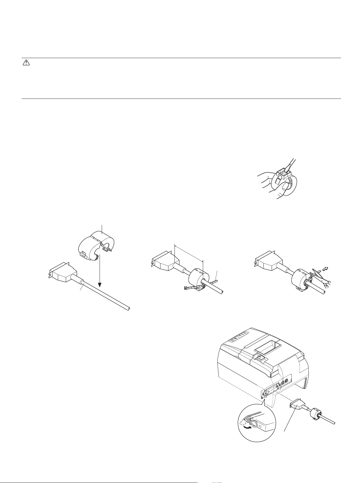
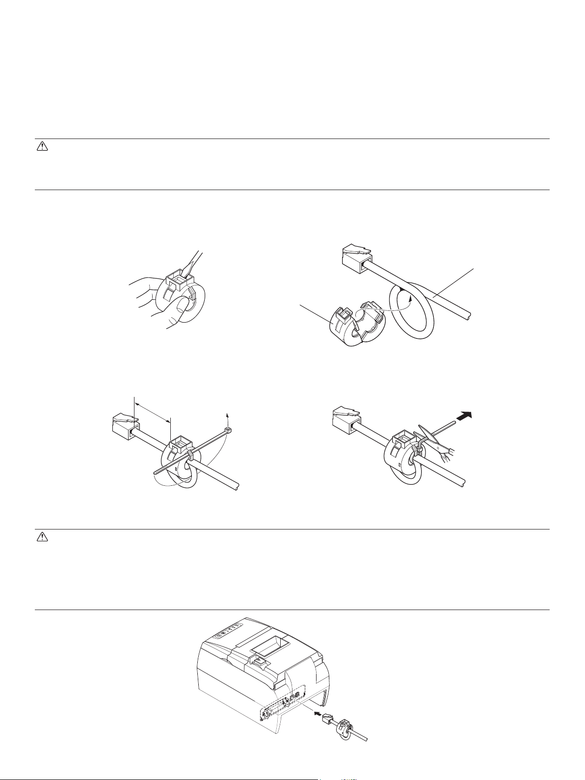
3-2-1. Parallel Interface Cable
(1) Make sure the printer is turn off.
(2) Afx the ferrite core onto the cable as shown in
the illustration.
(3) Pass the fastener through the ferrite core.
(4) Loop the fastener around the cable and lock it.
Use scissors to cut off any excess.
Ferrite core
5 cm
(maximum)
Interface cable
(5) Connect the interface cable to the connector on
the rear panel of the printer.
(6) Fasten the connector clasps.
Fastener
Pull and cut
POWER
ERROR
PAPER OUT
SLIP
FEED
RELEASE
– 7 –
Parallel interface
cable
Page 12
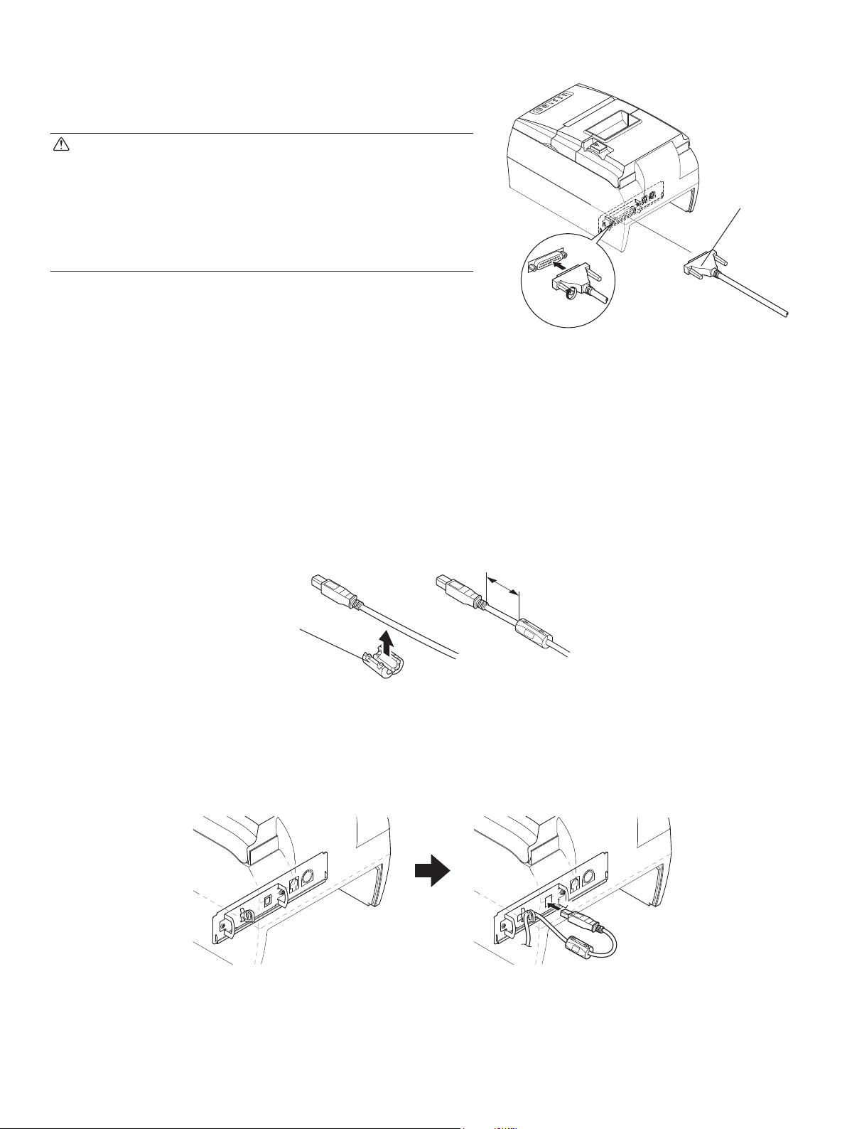
3-2-2. RS-232C Interface Cable
POWER
ERROR
PAPER OUT
(1) Make sure the printer is turn off.
SLIP
FEED
RELEASE
CAUTION
Before connecting/disconnecting the interface ca-
ble, make sure that power to the printer and all the
devices connected to the printer is turned off. Also
make sure the power cable plug is disconnected
from the AC outlet.
(2) Connect the interface cable to the connector on
the rear panel of the printer.
(3) Tighten the connector screws.
3-2-3. USB Interface Cable
Afx the ferrite core onto the USB cable as shown in the illustration below and make sure to
pass the cable through the cable support as shown in the illustration.
Option: USB CABLE 1.8M TSP1 (P/N: 30729100)
RS-232C
interface
cable
(1) Afx the supplied ferrite core onto the USB cable as shown in the illustration.
4 cm (Maximum)
Ferrite core
(2) Secure the cable with the cable hook.
(3) Insert the plug of the USB interface cable into the USB interface connector of the printer
as shown in the illustration.
– 8 –
Page 13
3-2-4. PoweredUSB Interface Cable
(1) Turn the power switch off.
(2) If connected to an AC adapter, pull the power cord plug from the outlet and then pull the
plug from the power connector on the printer side.
CAUTION
If connecting a PoweredUSB cable, do not connect the AC adapter because this can cause a
malfunction.
(3) Afx the ferrite core onto the cable as shown in the illustration.
Option: POWERED USB CABLE 1X8LNL 1.2M (P/N: 30729130)
(4) Pass the fastener through the ferrite core.
(5) Loop the fastener around the PoweredUSB interface cable and lock it.
Use scissors to cut off any excess.
Ferrite core
Interface cable
Maximum
3.5 cm
Fastener
(6) Connect the interface cable to the connector on the rear panel of the printer.
Pull and cut
– 9 –
Page 14

3-2-5. Connecting Ethernet Interface Cable
To protect the unit from electromagnetic interference, afx the two supplied ferrite cores to the
printer and router (hub) sides of the cable, respectively. Follow the instructions given below.
Option: LAN CABLE 1.0 M TSP1E (P/N: 30729200)
(1) Make sure the printer is turned off.
(2) Afx the ferrite core onto the Ethernet cable as shown in
the illustration below.
(3) Pass the fastener through the ferrite core.
(4) Loop the fastener around the cable and lock it. Use scis-
sors to cut off any excess.
10 cm
(maximum)
Ethernet cable
Ferrite core
Fastener
(5) Connect the interface cable to the connector on the
rear panel of the printer.
Pull and cut
Link disconnection detection feature
The Ethernet interface model is equipped with a link
disconnection detection feature.
If the printer is turned on when an Ethernet cable is not
connected to it, the POWER and ERROR lamps are
simultaneously turned on and off at 2-second intervals
to indicate the disconnection.
Be sure to connect the Ethernet cable from a PC or hub
to the printer, and then turn the printer on.
– 10 –
Page 15
3-3. Installing the Printer Software
Here is the procedure for installing the printer driver and utility software, which are stored on
the supplied CD-ROM.
The procedure applies to the Windows operating systems shown below.
For Macintosh and Linux, refer to the software manual in the Mac folder or Linux folder of
the CD-ROM.
• Windows 2000
• Windows XP
• Windows Vista 32-Bit/64-Bit
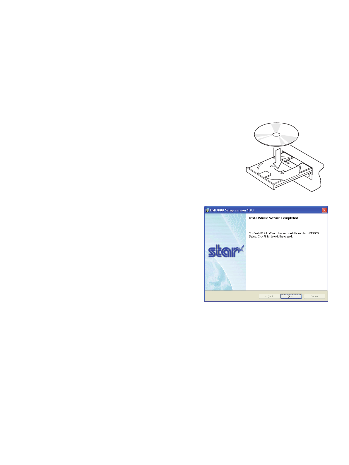
(1) Turn ON the power to your PC to start Windows.
(2) Insert the supplied CD-ROM (Drivers and Utilities)
into the CD-ROM drive.
(3) Follow the instructions that appear on the screen.
(4) The dialog shown in the illustration indicates that
the procedure has been completed.
Click “Finish”.
The dialog that appears on the screen varies with your system. This completes the installation
of the printer software. A message will appear, prompting you to restart. Restart Windows.
For instruction on the Windows Vista 64-Bit, refer to the software manual located in the
“Documents” folders on the CD-ROM.
– 11 –
Page 16

3-4. Connecting the Optional AC Adapter
Note: Before connecting/disconnecting the AC adapter, make sure that power to the printer
and all the devices connected to the printer is turned off. Also make sure the power
cable plug is disconnected from the AC outlet.
(1) Connect the AC adapter to the power cable.
Note: The optional AC adapter has been designed specically for this unit (HSP7000).
Other AC adapters may not meet the EMC technical standards.
Option: PS60A-24B
(2) Connect AC adapter to the connector on the printer.
(3) Insert the power cable plug into an AC outlet.
POWER
ERROR
PAPER OUT
SLIP
FEED
RELEASE
CAUTION
When disconnecting the cable, take hold of the cable
connector to pull it out. Releasing the lock makes it easy
to disconnect the connector.
Pulling the cable excessively could cause damage to the
connector.
– 12 –
Page 17
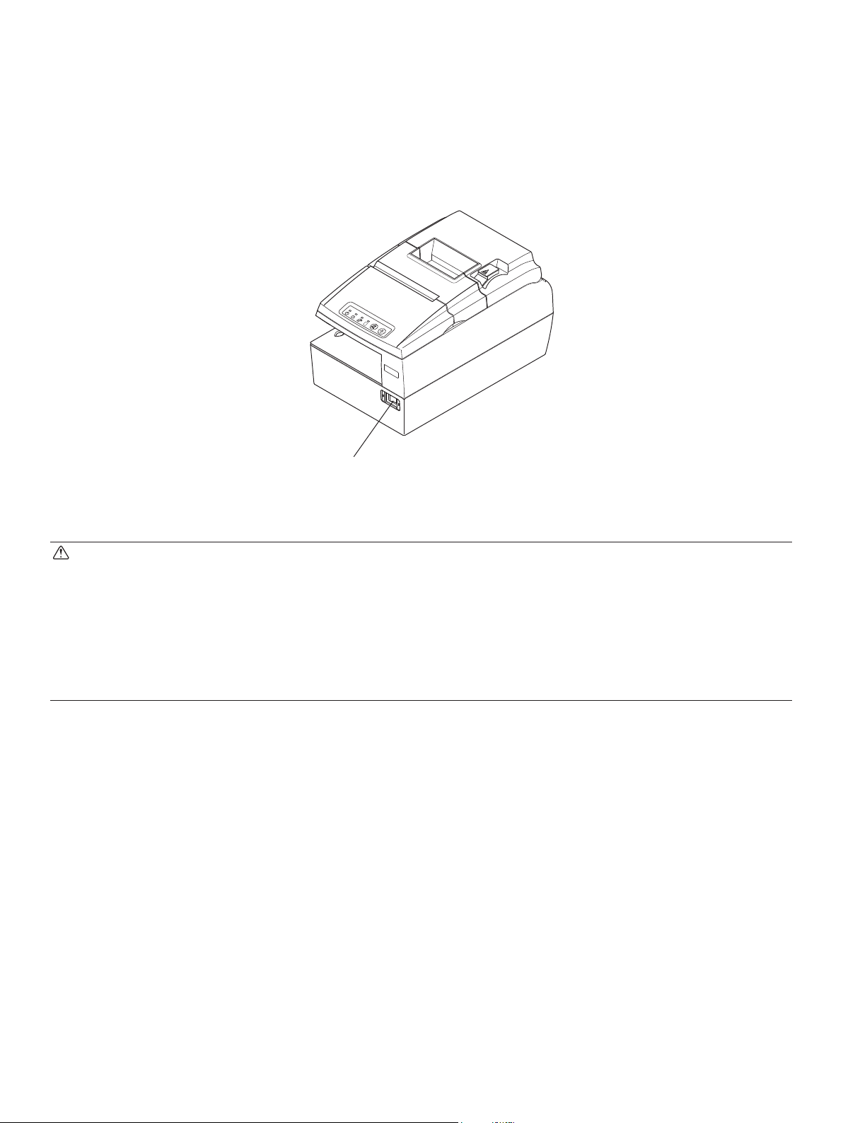
3-5. Turning Power On
Make sure that the Power cord has been connected as described in 3-4.
Turn ON the power switch located on the front of the printer.
The POWER lamp on the control panel will light up.
POWER
ERROR
PAPER OUT
SLIP
FEED
RELEASE
Power switch
CAUTION
We recommend that you unplug the printer from the power outlet whenever you do not plan to
use it for long periods. Because of this, you should locate the printer so that the power outlet it
is plugged into is nearby and easy to access.
When an Switch blind is afxed to the printer above the power switch, the ON/OFF marks of
the power switch may be hidden. If this occurs, remove the power cord from the outlet to turn
the printer OFF.
– 13 –
Page 18

3-6. Switch Blind Installation
It is not necessary to install the switch blind. Only install it if it is necessary for you. By installing the switch blind, the following become possible.
• Preventing the power switch from being operated by mistake.
• Ensuring that other people can not easily operate the power switch.
Install the switch blind as shown in the diagram below.
POWER
ERROR
PAPER OUT
SLIP
FEED
RELEASE
Switch blind
The power switch can be turned ON (
|
pen etc.) in the holes in the switch blind.
CAUTION
We recommend that you unplug the printer from the power outlet whenever you do not plan to
use it for long periods. Because of this, you should locate the printer so that the power outlet it
is plugged into is nearby and easy to access.
) and OFF (O) by inserting a narrow instrument (ball
– 14 –
Page 19
3-7. Connecting to a Peripheral Unit
You can connect a peripheral unit to the printer using a modular plug.
See “15. Peripheral Unit Drive Circuit” for details about the type of modular plug that is required. Note that this printer does not come with a modular plug or wire, so it is up to you to
obtain one that suits your needs.
CAUTION
Make sure that the printer is turned off and unplugged from the AC outlet and that the computer
is turned off before making connections.
(1) Make sure the printer is turned off.
(2) Afx the ferrite core onto the peripheral drive cable as shown below.
Peripheral drive cable
Ferrite core
(3) Pass the fastener through the ferrite core.
(4) Loop the fastener around the peripheral drive cable and lock it.
Use scissors to cut off any excess.
3.5 cm (maximum)
Pull and cut
(5) Connect the peripheral drive cable to the connector on the rear panel of the printer.
CAUTION
Do not connect a telephone line into the peripheral drive connector. Failure to observe this may
result in damage to the printer.
Also, for safety purposes, do not connect wiring to the external drive connector if there is a
chance it may carry peripheral voltage.
POWER
ERROR
PAPER OUT
SL
IP
FEED
RELE
ASE
– 15 –
Page 20
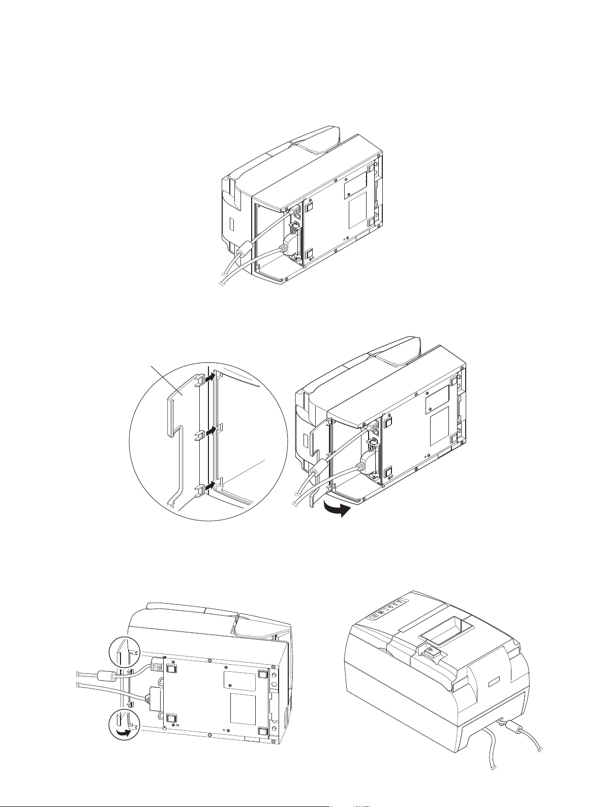
3-8. Attaching the Interface Cover
It is not necessary to attach the interface cover. Only attach it if it is necessary for you.
Attach the interface cover as shown in the illustration.
(1) Place the printer as shown below.
(2) Install the interface cover by aligning the tabs on the interface cover with the grooves in
the printer case.
Interface cover
(3) Place the AC cable and the interface cable in the cutout of the interface cover. Then, install
the interface cover until the both ends of the interface cover click into place.
POWER
ERROR
PAPER OUT
SLIP
FEED
RELEASE
– 16 –
Page 21
4. Loading the Ribbon Cartridge and Paper
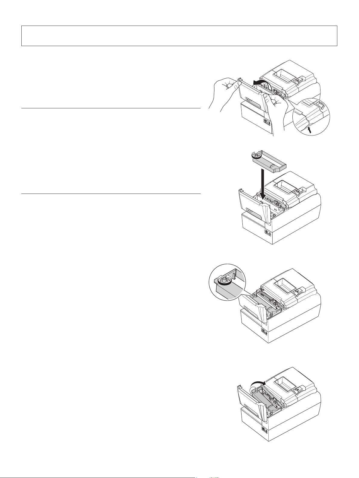
4-1. Loading the Ribbon Cartridge
(1) Turn off power to the printer.
(2) Open the front cover by holding the nger grips
on both ends of the cover and lifting it up.
Important!
1. Do not touch the print head immediately after
printing as it can be extremely hot.
2. Do not touch the cutter blade.
· There is a cutter inside the paper outlet slot.
Not only should you not put your hand in the
paper outlet slot while printing is in progress,
never put your hand into the outlet even when
printing is not in progress.
(3) Place the ribbon cartridge in the direction shown
in the gure and press it down to load it. If loading
of the ribbon cartridge is not satisfactory, press
down the cartridge while rotating the ribbon feed
knob in the direction of the arrow.
(4) Turn the ribbon feed knob of the ribbon cartridge
in the direction of the arrow to remove slack in
the ribbon.
(5) Close the front cover.
Note: When removing the ribbon cartridge, raise
the nger grip as shown in the gure.
– 17 –
Page 22
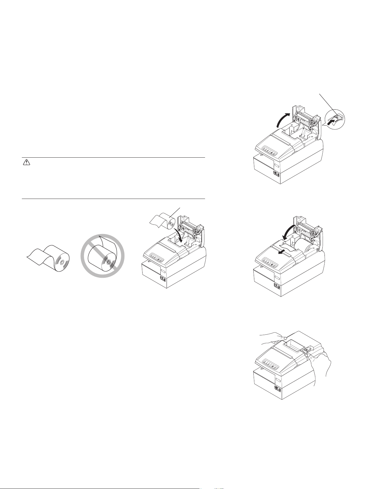
4-2. Loading the Paper Roll
4-2-1. Using 79.5 mm Width Paper Roll
Be sure to use roll paper that matches the printer’s specication.
When using a paper roll with an 57.5 mm width, install the paper guide as described on the
following page.
(1) Push the cover open lever, and open the printer
cover.
(2) While observing the direction of the roll, set the
paper roll into the hollow, and pull on the leading
edge of the paper toward you.
CAUTION
Do not pull out the end of the paper diagonally,
as it will cause the paper to become jammed or
skewed.
Paper roll
ERROR
PAPER
OUT
SLI
P
FEED
RE
LEASE
Cover open lever
ERROR
PAPER OUT
SLIP
FEED
RELEASE
ERROR
PAPER OUT
SLIP
FEED
RELEASE
(3) Push down both sides of the printer cover to
close.
Note: Make sure that the printer cover is securely
closed.
(4) If the printer cover is closed after turning on the
power, the cutter operates automatically and the
front end of the paper is cut.
– 18 –
POWER
ERROR
PAPER OUT
SLIP
FEED
RELEASE
Page 23
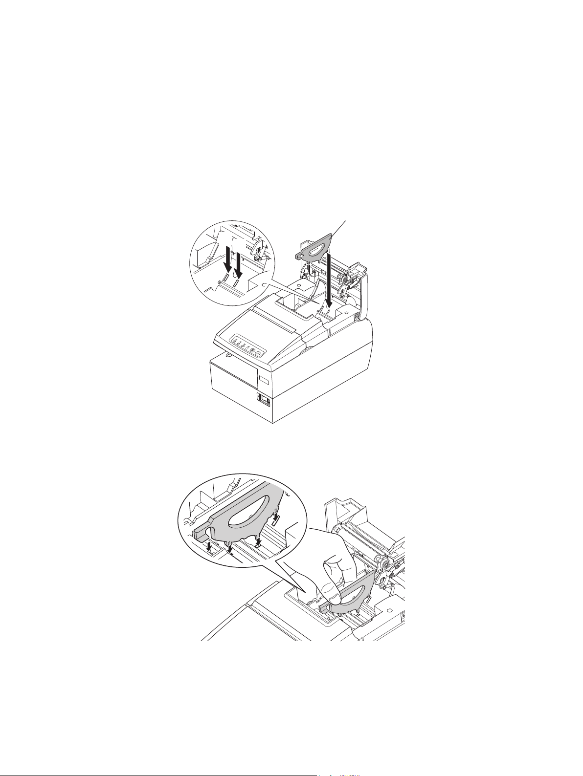
4-2-2. Using 57.5/75.5 mm Width Paper Roll
When using a paper roll with 57.5 or 75.5 mm width, install the supplied paper guide on the
printer.
To change the effective print width (roll paper width), change the setting at memory switch
conguration Utility. For details on the setting of the memory switches, refer to the software
manual located in the “Documents” folders on the CD-ROM.
(1) Install the roll paper guide in the unit as illustrated below.
To use a 75.5 mm width paper roll, align the roll paper guide in hole [1], and to use a 57.5
mm width paper roll, align it in hole [2].
Paper guide
[1]
[2]
POWER
ERROR
PAPE
R
OUT
SLIP
FEED
RELEASE
(2) Install the roll paper guide in the unit by aligning it with the holes and grooves as illustrated
below.
Note: After using a paper roll with a width of 57.5 mm, do not change to a paper roll with
a width of 79.5 or 75.5 mm. (This is because the printer head has deteriorated as a
result of a portion of the head having been in direct contact with the platen.)
After using a paper roll with a width of 75.5 mm, do not change to a paper roll with
a width of 79.5 mm. for same reason.
– 19 –
Page 24

4-3. Loading the Slip Paper or Validation Paper
POWER
ERROR
PAPER OUT
SLIP
FEED
RELEASE
Before starting printing, make sure the ribbon cassette is placed in the printer. (See “4-1. Loading the Ribbon Cartridge” for details.)
Insert the paper as follows:
(1) Turn the printer power switch ON.
(2) Insert the paper as illustrated below. Facing the printer, insert the paper straight, while
sliding the right end of the paper against the right end of the slip paper slot. Alternatively,
insert the paper straight from the top.
Note: Sliding the paper diagonally can cause a paper jam. If the paper gets jammed, press
the RELEASE button to remove the paper. Then, insert the paper again.
(See “8-2. Removing Paper Jam” for details.)
Inserting Slip Paper
RELEASE
RELEASE
FEED
SLIP
PAPER OUT
ERROR
POWER
FEED
SLIP
PAPER OUT
ERROR
POWER
Inserting Validation Paper
2
1
1
2
RELEASE
FEED
SLIP
PAPER OUT
ERROR
POWER
(3) When the printer detects a paper, it automatically feeds the paper and starts printing.
(4) After completing printing, the printer will automatically release the paper.
Note: Be sure to use a type of paper that matches the printer’s specications. (See “5-2-1.
Specications”.) Do not use paper that is curled, kinked, wrinkled, warped, or
torn.
– 20 –
Page 25

4-4. Scanning MICR Characters
The insertion direction for MICR paper varies according to the model.
HSP7543 (no MICR scanning head): MICR characters cannot be scanned.
HSP7643 (MICR scanning head installed above):
Insert the MICR paper with the MICR characters facing
up.
HSP7743 (MICR scanning head installed below):
Insert the MICR paper with the MICR characters facing
down.
Insert a MICR paper as follows:
(1) Turn the printer power switch ON.
(2) Make sure the SLIP lamp is ashing.
As you face the printer, insert the paper straight, while sliding the right end of the MICR
(3)
paper against the right end of the slip paper slot.
Note: Sliding the paper diagonally can cause a paper jam.
If the paper gets jammed, press the RELEASE button to remove the paper. Then,
insert the paper again. (See “8-2. Removing Paper Jam” for details.)
(4) When the MICR paper reaches the scanning position, the SLIP lamp will turn ON.
<Direction of MICR Paper on HSP7643>
100
P L E
RELEASE
FEED
SLIP
PAPER OUT
ERROR
POWER
10 0
Scanning
characters
S A M P L E
RELEASE
FEED
SLIP
PAPER OUT
ERROR
POWER
<Direction of MICR Paper on HSP7743>
RELEASE
FEED
SLIP
PAPER OUT
ERROR
POWER
Scanning
characters
RELEASE
FEED
SLIP
PAPER OUT
ERROR
POWER
– 21 –
Page 26

Notes:
1) For MICR scanning, do not place the printer near devices that generate magnetism or
in an area that can expose the printer to shocks or vibration. Placing the printer in such
areas can negatively affect its scanning performance. Before putting the printer into
actual operation, verify the printer’s scanning performance by performing trial scans
at its installed location.
2) Use at MICR paper that is not curled, kinked, wrinkled, warped, or torn. Otherwise,
the ink ribbon could become abraded or soiled, or it could cause a paper jam.
3) Do not use MICR paper with clips, staples, or debris attached to it. Otherwise, it could
damage the MICR scanning head, in addition to causing a paper jam.
Caution Symbol
This symbol is placed near the slip print head to indicate that it may be hot.
Never touch the slip print head immediately after the printer has been used. Let the
print head cool for a few minutes before touching it.
This symbol is placed near the thermal print head to indicate that it may be hot.
Never touch the thermal print head immediately after the printer has been used. Let
the print head cool for a few minutes before touching it. Observe the precautions
for handling electrostatic sensitive devices.
This symbol is placed near the cutter.
Never touch the cutter blade, as you could injure your ngers.
This symbol is placed near the peripheral drive connector.
Do not connect this to a telephone.
WARNING
P Shut down your equipment immediately if it produces smoke, a strange odor, or unusual
noise. Immediately unplug the equipment and contact your dealer for advice.
P Never attempt to repair this product yourself. Improper repair work can be dangerous.
P Never disassemble or modify this product. Tampering with this product may result in injury,
re, or electric shock.
P Do not touch the cutter blade.
• There is a cutter inside the paper outlet slot. Not only should you not put your hand in the
paper outlet slot while printing is in progress, never put your hand into the outlet even
when printing is not in progress.
• The printer cover can be opened when replacing the paper. However, since the cutter
blade is on the inside of the printer cover, be careful not to place your face or hands too
close to the cutter blade.
P During and immediately after printing, the area around the print head is very hot. Do not
touch it, as you could be burned.
P Since working on the cutter may be dangerous, be sure to turn off the printer rst.
– 22 –
Page 27

CAUTION
P We recommend that you unplug the printer from the power outlet whenever you do not plan
to use it for long periods. Because of this, you should locate the printer so that the power
outlet it is plugged into is nearby and easy to access.
P If the voltage shown on the label on the of your printer does not match the voltage for your
area, contact your dealer immediately.
P Make sure that the printer is turned off and unplugged from the AC outlet and that the
computer is turned off before making connections.
P Do not connect a telephone line into the peripheral drive connector.
Failure to observe this may result in damage to the printer.
Also, for safety purposes, do not connect wiring to the external drive connector if there is
a chance it may carry peripheral voltage.
P Do not operate the open lever while pressing on the rear cover with your hand.
P Do not pull the open lever and open the rear cover when printing is in progress or when
the auto cutter is operating.
P Do not pull out paper while the rear cover is closed.
P If liquids, foreign objects (coins and paper clips), and so on enter the printer, turn off the
printer, unplug it from the AC outlet, and contact your dealer for advice.
Continued use could cause a short circuit, which may result in re or electric shock.
P The heating element and the driver IC of the thermal head are easily damaged. Do not touch
them with metal objects, sandpaper, etc.
P Printing quality may suffer if the thermal head heating element becomes soiled by being
touched with your hands. Do not touch the thermal head heating element.
P There is a risk of damage to the driver IC of the thermal head from static electricity. Never
directly touch the IC.
P The printing quality and working life of the thermal head cannot be guaranteed if any ther-
mal paper other than that recommended is used. In particular, thermal paper containing
+
, K+, C1-] may drastically reduce the working life of the thermal head. Please exercise
[Na
caution.
+
The use of paper with a maximum ion density of Na
ppm is recommended.
P Do not operate the printer if there is moisture on the front surface of the head from conden-
sation, etc.
500 ppm, K+ 150 ppm, and Cl– 300
Notes on Using the Auto Cutter
P To print after a cut, feed 1 mm (8-dot line) or more of paper.
P If the cutter is not in its home position after an error, rst eliminate the cause of the error;
then, turn the power back ON.
P A margin of 5 mm or more is recommended from the end of the printed area to the cutting
position.
P Do not attempt to remove the paper during a cut, as this can cause a paper jam.
– 23 –
Page 28

5. Consumable Parts and AC Adapter
Use paper that meets the specications.
5-1. Thermal Paper Roll
5-1-1. Paper roll specication
(1) Thickness: Normal paper 65~85 µm (excluding Mitsubishi HiTec F5041)
Label paper 65~150 µm (cutter is not supported)
(2) Width: General thermal paper 79.5±0.5 mm (57.5±0.5 mm/75.5±0.5 mm
when the paper roller holder is used)
Label paper 76.5 ± 0.5 mm
(3) Outer roll diameter: ø83 mm or less
Take up paper roll width: 80
(4) Core outer/inner diameter:
Paper type Core outer Core inner
Normal paper: ø18±1 mm ø12±1 mm
Label paper: ø32±1 mm ø25.4±1 mm
(5) Printed surface: Outer edge of roll * Do not use an inner wrapped roll paper.
+0.5
mm or (58
-1
holder is used)
+0.5
mm/76
-1
+0.5
mm when the paper roller
-1
CAUTION
1) Do not glue or tape the roll paper and shaft core together.
2) Do not use paper rolls that have the tail end folded.
3) The trailing edge should not be folded.
– 24 –
Page 29

5-1-2. Effective Print Width
Paper Width
(mm)
Right / Left Margin (mm) Effective Print Width
(mm)
79.5 ± 0.5 3.75 72 48
75.5 ± 0.5 3.75 68 45
57.5 ± 0.5 Left 2.75, Right 3.75 51 34
Label Width
(mm)
76.5 ± 0.5 2 72 48
Right / Left Margin (mm) Effective Print Width
(mm)
Left Margin Right MarginEffective Print Width
Number of Print Columns (12 × 24 Font)
Number of Print Columns (12 × 24 Font)
Paper Width
– 25 –
Page 30

5-2. Slip Paper
5-2-1. Specications
(1) Width: 68 ~ 230 mm
(2) Length: 75 ~ 297 mm
(3) No. of copies: original + 3 copies
(4) Total thickness: 1 sheet 0.09 ~ 0.15 mm (up to A4 portrait)
0.09 ~ 0.20 mm (up to A6 portrait)
4 sheets 0.09 ~ 0.31 mm
(5) Copy slippage: 1.5 mm or less per 15 lines (between original and bottom-
most paper)
(6) Adhesive: top-bound = good; right-bound = acceptable;
left-bound = acceptable; bottom-bound = unacceptable
Note: Be particularly careful with paper that has adhesive on the left end because it might
feed diagonally.
Note:
1) Do not use paper that is curled, kinked, wrinkled, warped, or torn.
2) Do not use paper that has holes in the positions shown below, and do not print on the
back of paper that has low reectance, because they can cause the paper sensor to
operate improperly.
37 mm
27 mm
8 mm
: Holes not allowed
: Printing not allowed on pa-
per with holes or reectance
below 40%
Paper feed
direction
3) The copying performance of the printer is greatly affected by the ambient temperature.
Therefore, print under the conditions described below.
Number of copies Ambient temperature
Original + 3 copies 10 ~ 40°C
Original + 1 copy 5 ~ 45°C
– 26 –
Page 31

5-2-2. Slip Printing Area
The printing position is as shown in the diagram below.
5
Paper feed roller (rear)
Paper stop position
Paper feed roller (front)
Paper feed direction
TOF sensor
3.1
First line printing
COF sensor
Last line printing
85.4
13.5 13.529.5
13.5
29.5
BOF sensor
31.8
32.6
13.5
15.1
15.1
5.6
59.1 16.3
14.811
1.9
Approx. 83.5
28.2
18.4
Minimum
(unit: mm)
5-2-3. Validation Printing Range
150 (Min)
5.6
53 (Max)
18.4 (Min)
(unit: mm)
68 (Min)
36.1
33
(printable area)
85.4
3.1
5-3. AC adapter (option)
Note: The optional AC adapter has been designed specically for this unit (HSP7000).
Other AC adapters may not meet the EMC technical standards. In addition, use of
other AC adapters may result in damage to the printer, re or electric shock.
Model name: PS60A-24B
Input: 90 to 264 V AC, 50/60 Hz
Output: DC24 V ±5%, 2.0 A (5.0 A Load 10 sec. Max.)
– 27 –
Page 32

6. Control Panel and Other Functions
6-1. Control Panel
1 POWER Lamp (Green)
2 ERROR Lamp (Red)
3 PAPER OUT Lamp (Red)
4 SLIP Lamp (Green)
5 FEED Button 6 RELEASE Button
1 POWER Lamp (Green)
Lights when the printer is online.
Describes various errors in combination with other lamps.
2 ERROR Lamp (Red)
Lights when the cover is open.
Describes various errors in combination with other lamps.
3 PAPER OUT Lamp (Red)
Describes the condition of the roll paper.
Describes various errors in combination with other lamps.
4 SLIP Lamp (Green)
Describes the condition of the slip paper when SLIP is selected.
Describes various errors in combination with other lamps.
5 FEED Button
While the printer is online, feeds the roll paper.
6 RELEASE Button
Releases the slip paper.
– 28 –
Page 33

6-2. Errors
(1) Recoverable errors
Error Description POWER
Lamp
Thermal head high
temperature detection error
Impact head high
temperature detection error
Roll paper near-end
detection
Thermal (rear) cover
open error
Slip (front) cover
open error
Thermal paper out
or jam error
Slip paper jam/TOF/
BOF/COF error
Cutter error (cutting
error)
Link disconnection
detection*1
Flashes at
2 second
intervals.
Flashes at
2 second
intervals.
ON OFF Flashes at
ON ON — OFF Recovered by closing the
ON ON — ON Recovered by closing the
ON OFF Flashes at
ON OFF — Flashes at
OFF Flashes at
Flashes at
2 second
intervals.
ERROR
Lamp
OFF OFF OFF Automatically recovered
OFF OFF ON Automatically recovered
0.5 second
intervals
Flashes at
2 second
intervals.
PAPER
OUT
Lamp
4 second
intervals.
1 second
intervals
OFF OFF Recovered when the cutter
— — Connect an Ethernet cable.
SLIP
Lamp
OFF Indicates that the end of the
OFF Recovered by loading a
0.25 second intervals
Recovery Conditions
after the thermal head has
cooled.
after the impact head has
cooled.
roll paper is approaching.
Recovered by loading a
new paper roll and closing
the rear cover.
thermal (rear) cover.
slip (front) cover.
paper roll or clearing the
paper jam, reloading the
paper roll, and closing the
rear cover.
Recovered by loading
paper or clearing the
paper jam, reloading the
paper, and closing the rear
cover.
returns to its home position
after the power is turned
OFF and then ON. (See
notes 1 and 2)
For details, see section
3-2-5, "Ethernet Interface
Cable."
*1 Ethernet interface model only
Note:
1) If the cutter doesn’t return to the home position or doesn’t perform the initial movement, it cannot be recovered. See “8-3. Releasing a Locked Cutter” for details.
2) If the paper is jammed, turn the power off, clear the jammed paper, then turn the power
ON.
See “8-2. Removing Paper Jam” for details.
– 29 –
Page 34

2) Non-recoverable errors
Error Description POWER
Lamp
RAM error OFF Flashes at
EEPROM error OFF Flashes at
Flash memory error
Clamp error OFF Flashes at
Validation color OFF Flashes at
Thermal head error OFF Flashes at
Impact head error OFF Flashes at
Home position error
Power voltage error
OFF Flashes at
OFF Flashes at
OFF Flashes at
ERROR
Lamp
0.5 second
intervals
1 second
intervals
2 second
intervals
0.5 second
intervals
0.5 second
intervals
1 second
intervals
1 second
intervals
1 second
intervals
2 second
intervals
PAPER
OUT
Lamp
Flashes at
0.5 second
intervals
Flashes at
1 second
intervals
Flashes at
2 second
intervals
OFF ON This is not a recoverable
Flashes at
0.5 second
intervals
OFF OFF This is not a recoverable
OFF ON This is not a recoverable
Flashes at
1 second
intervals
Flashes at
2 second
intervals
SLIP
Lamp
Flashes at
0.5 second
intervals
Flashes at
1 second
intervals
Flashes at
2 second
intervals
ON This is not a recoverable
ON This is not a recoverable
OFF This is not a recoverable
Recovery Conditions
This is not a recoverable
error.
This is not a recoverable
error.
This is not a recoverable
error.
error.
error.
error.
error.
error.
error.
Note:
1) If a non recoverable error occurs, turn the power OFF immediately.
2) When Power supply error occurs, there is a possibility that the power supply unit has
a trouble.
For other non recoverable errors, please consult the dealer for repairs.
– 30 –
Page 35

6-3. Self-Printing
6-3-1. Test Printing
• Thermal paper roll
(1) Place a paper roll on the printer.
(2) With the rear cover closed, turn the power switch ON while keeping the FEED button
depressed.
(3) The printer will run a test print in the following order: version number, DIP switch
settings, memory switch settings, etc.
After the test print is completed, the printer will revert to the normal mode.
• Slip paper
(1) With the front cover closed, turn the power switch ON while keeping the RELEASE
button depressed.
(2) Insert a paper into the slip slot. The printer will automatically feed the paper; then, it
will run a test print.
The printer will run a test print in the following order: version number, DIP switch
settings, memory switch settings, etc.
After completing the test print, the printer will release the paper and revert to the
normal mode.
– 31 –
Page 36

6-3-2. Hexadecimal Dump Mode
(1) Place the thermal paper roll on the printer.
Open the rear cover, then turn the power on while holding the FEED button.
(2) When the rear cover is closed, “*** HEX DUMP PRINTING ***” is printed, and the
printer enters the Hexadecimal Dump Mode.
(3) Each of the signals sent from the computer to the printer will be printed out in hexadecimal
code.
This function allows you to check if a control code sent to the printer by the program being
used is correct or not.
(4) The nal line is not printed if its data is less than one full line. However, if the FEED but-
ton is pushed, the nal line is printed. To turn off the mode, it is necessary to turn off the
printer completely.
– 32 –
Page 37

6-3-3. Impact Head Printing Dot Alignment Adjustment Mode
(1) With the front cover open, turn the power ON while keeping the RELEASE button
pressed.
(2) Close the front cover and place the paper in the printer. Then, the printer will print “Dot
Alignment Adjust Mode” and enter the impact head dot alignment adjustment mode. The
printer will continue printing a total of 22 patterns of dot alignment adjustments as shown
below. The patterns are staggered in 1/8-dot increments.
The printed line above each pattern shows a number between 1 and 23 and its setting value
(Lv.xx). The pattern preceded by a “*” mark indicates the present setting value.
(3) As shown below, the adjustment patterns that are printed consist of a three-dot bar each
at the top and bottom for the forward pass, and a three-dot bar in the middle for the backward pass. Check the patterns visually and select a pattern with the three bars forming the
straightest line.
Forward pass
Backward pass
Forward pass
Improper
correction
Optimal
correction
Improper
correction
(4) To set up a pattern, press the RELEASE button as many times as the number (1 to 23) of
the desired pattern. In the process, a buzzer will make a short sound (0.1 second) with each
pressing of the RELEASE button.
– 33 –
Page 38

(5) Repeat step (4). At the pattern number that you wish to accept, keep the RELEASE but-
ton depressed (approx. 2 seconds) until the buzzer makes a long (0.5 second) sound. This
completes the acceptance of the setting.
Example: To accept the No. 4 setting, short-press the RELEASE button three times. At
the fourth time, keep the RELEASE button depressed.
Note: If you press the RELEASE button 24 or more times, it will exceed the available range
of settings. This will cause the warning buzzer (0.1 second) to sound four times, and
will delete the number of pressings of the button. Go back to step (4) to resume the
setup process.
(6) If you do not nd an optimal correction pattern among the printed patterns, perform the
“Backward” or “Forward” operation as indicated in No. 1. These operations will allow
you to make printing pattern adjustments with a greater range of dot corrections. After
performing steps (1) to (3), perform the respective operations as follows:
For a “Backward” operation, keep the RELEASE button depressed (approx. 2 seconds)
until the buzzer makes a long (0.5 second) sound.
→ The printer will release the paper with a printing pattern in which the backward pass
is corrected rightward of the current printing pattern.
For a “Forward” operation, keep the RELEASE button depressed until the buzzer makes
a long (0.5 second) sound. Then, continue pressing and holding (approx. 4 seconds) the
RELEASE button until the buzzer makes a short (0.1 second) sound and another long (0.5
second) sound.
→ The printer will release the paper with a printing pattern in which the backward pass
is corrected leftward of the current printing pattern.
(7) The printer will write the setting value, which you have accepted, on the nonvolatile memory.
For conrmation, the printer will print out ve patterns (which includes the setting value
that you have accepted, as well as the preceding and succeeding patterns) and an “Adjust
Completed” message.
This is followed by the release of the paper and the resetting of the printer.
Note: During the period between the time you accepted the setting value and the printer
starts to print as described above, the printer will write the setting value on the
memory. Never turn the power OFF or reset the printer during this period. Doing so
will corrupt the dot adjustment settings as well as other settings.
If you make a mistake in the settings, do not turn the power OFF in the middle of
the process. Instead, wait until the printer completes the nal reset and start the dot
adjustment mode from the beginning.
– 34 –
Page 39

6-4. Cleaning Mode
Perform the following procedure to enter the cleaning mode. See “9-3. MICR Head” in
“9. Maintenance” for details on cleaning the MICR head.
(1) With the rear cover closed, turn the power switch ON while keeping both the FEED button
and RELEASE button depressed.
(2) Insert the cleaning sheet. Cleaning starts.
(3) The printer is reset when the cleaning is complete.
6-5. Sensor Adjustment
This printer is equipped with the following ve
paper sensors:
• PE (Paper End) Sensor
Detects whether a roll paper is loaded on the
printer.
• NE (Near End) sensor
Detects whether the roll paper is nearing its
end.
• BOF (Bottom of Feed) Sensor
Detects whether a slip paper is placed on the
printer.
BOF Sensor
• COF (Center of Feed) Sensor
Detects the feed position for printing on a slip
of paper.
• TOF (Top of Feed) Sensor
Detects the top of feed of a slip paper.
The aforementioned sensors can be adjusted as follows.
PE Sensor
COF Sensor
NE Sensor
TOF
Sensor
6-5-1. PE Sensor Adjustment Mode
(1) Make sure the printer power is turned OFF.
(2) Open the rear cover and set a paper roll in place, thus setting the printer in the “paper
present” state.
ERROR
P
APER
OUT
SLI
P
FEED
RE
LEASE
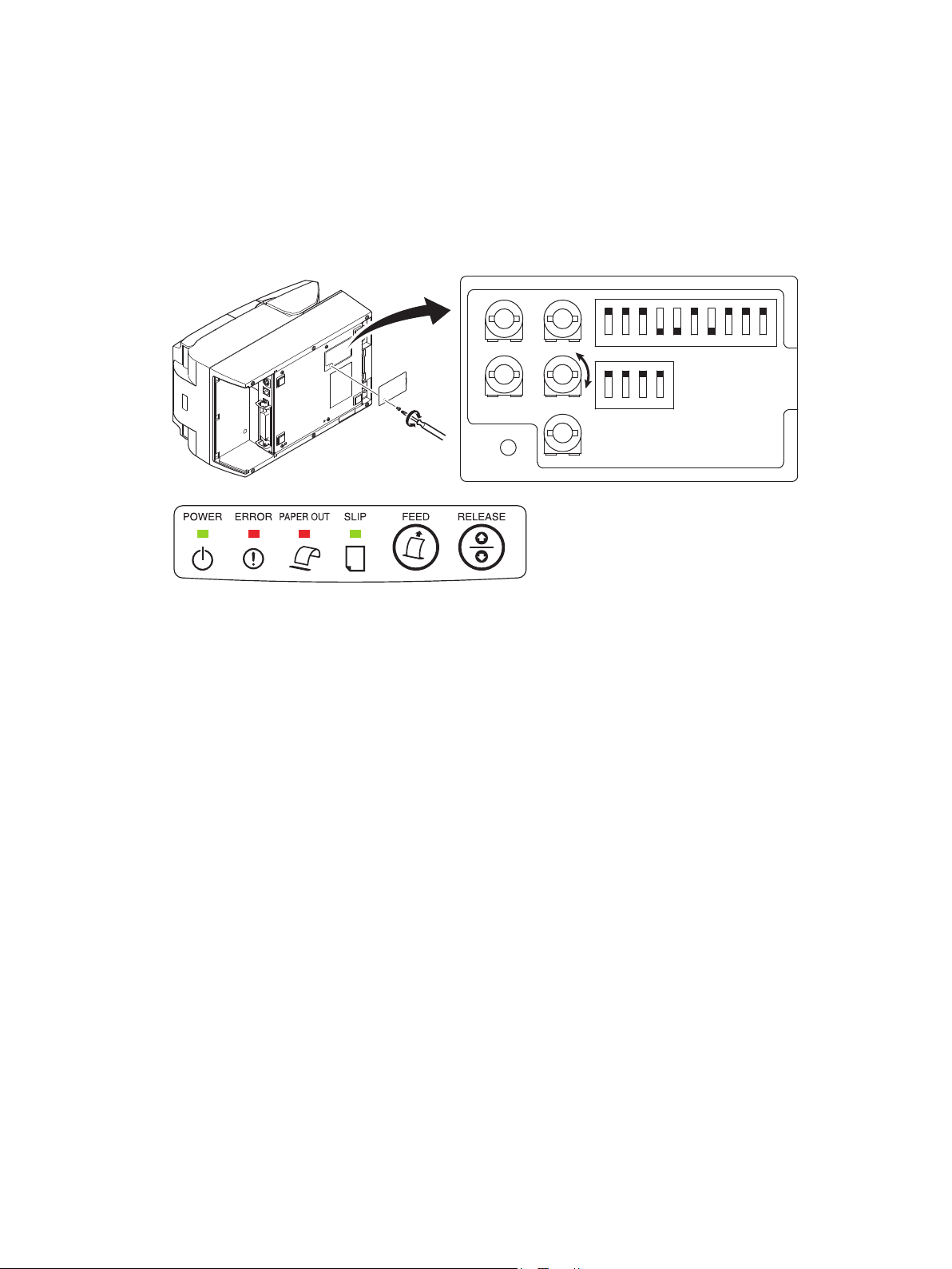
(3) Undo the screws and remove the DIP switch cover from the bottom of the printer.
(4) Using the tip of a ballpoint pen or a similar object, set the DIP switches as follows: DIPSW1-4
OFF, DIPSW1-5 ON, DIPSW1-6 OFF, DIPSW1-7 and DIPSW1-8 ON. Turn the printer
power ON.
The lamps on the control panel will ash, and the printer will enter the sensor adjustment
mode.
– 35 –
Page 40

(5) Using a small slot screwdriver, turn VR1 as shown below, and adjust it so that all the lamps
are lit: POWER lamp (green: constant ON), ERROR lamp (red), PAPER OUT lamp (red),
and SLIP lamp (green).
VR1
VR2
VR3
VR4
VR5
1 2 3 4 5 6 7 8 9
1 2 3 4
10
(6) Turn the printer power OFF, and restore the DIP switches DIPSW1-4, DIPSW1-5, DIPSW1-6,
DIPSW1-7, and DIPSW1-8 to their original settings.
6-5-2. NE Sensor Adjustment Mode
(1) Make sure the printer power is turned OFF.
(2) Open the rear cover and remove the paper roll, thus setting the printer in the “paper absent”
state.
ERROR
PAPER OUT
SLIP
FEED
RELEASE
(3) Undo the screws and remove the DIP switch cover from the bottom of the printer.
(4) Using the tip of a ballpoint pen or a similar object, set the DIP switches as follows:
DIPSW1-4, DIPSW1-5 and DIPSW1-6 OFF, and DIPSW1-7 and DIPSW1-8 ON. Turn
the printer power ON.
The lamps on the control panel will ash, and the printer will enter the sensor adjustment
mode.
– 36 –
Page 41

(5) Using a small slot screwdriver, turn VR2 as shown below, and adjust it so that all the lamps
are lit: POWER lamp (green: constant ON), ERROR lamp (red), PAPER OUT lamp (red),
and SLIP lamp (green).
VR1
VR2
VR3
VR4
VR5
1 2 3 4 5 6 7 8 9
1 2 3 4
10
(6) Turn the printer power OFF, and restore the DIP switches DIPSW1-4, DIPSW1-5, DIPSW1-6,
DIPSW1-7, and DIPSW1-8 to their original settings.
6-5-3. BOF Sensor Adjustment Mode
(1) Make sure the printer power is turned OFF.
(2) Set the slip slot in the “paper absent” state.
(3) Undo the screws and remove the DIP switch cover from the bottom of the printer.
(4) Using the tip of a ballpoint pen or a similar object, set the DIP switches as follows: DIPSW1-4
OFF, DIPSW1-5 and DIPSW1-6 ON, DIPSW1-7 OFF, and DIPSW1-8 ON. Turn the printer
power ON.
The lamps on the control panel will ash, and the printer will enter the sensor adjustment
mode.
(5) Using a small slot screwdriver, turn VR3 as shown below, and adjust it so that all the lamps
are lit: POWER lamp (green: constant ON), ERROR lamp (red), PAPER OUT lamp (red),
and SLIP lamp (green).
VR1
VR2
– 37 –
VR3
VR4
VR5
1 2 3 4 5 6 7 8 9
1 2 3 4
10
Page 42

(6) Turn the printer power OFF, and restore the DIP switches DIPSW1-4, DIPSW1-5, DIPSW1-6,
DIPSW1-7, and DIPSW1-8 to their original settings.
6-5-4. COF Sensor Adjustment Mode
(1) Make sure the printer power is turned OFF.
(2) Insert a slip paper to set the printer in the “paper present” state.
To do so, open the front cover as shown below and insert the paper diagonally from the
left.
Set the paper straight while pressing on the platen. Then, close the front cover.
RELEASE
FEED
SLIP
PAPER OUT
ERROR
POWER
(3) Undo the screws and remove the DIP switch cover from the bottom of the printer.
– 38 –
Page 43
(4) Using the tip of a ballpoint pen or a similar object, set the DIP switches as follows: DIPSW1-4
and DIPSW1-5 OFF, DIPSW1-6 ON, DIPSW1-7 OFF, and DIPSW1-8 ON. Turn the printer
power ON. The lamps on the control panel will ash, and the printer will enter the sensor
adjustment mode.
(5) Using a small slot screwdriver, turn VR4 as shown below, and adjust it so that all the lamps
are lit: POWER lamp (green: constant ON), ERROR lamp (red), PAPER OUT lamp (red),
and SLIP lamp (green).
VR1
VR2
VR3
VR4
VR5
1 2 3 4 5 6 7 8 9
1 2 3 4
10
(6) Turn the printer power OFF, and restore the DIP switches DIPSW1-4, DIPSW1-5, DIPSW1-
6, DIPSW1-7, and DIPSW1-8 to their original settings.
6-5-5. TOF Sensor Adjustment Mode
(1) Make sure the printer power is turned OFF.
(2) Insert a slip paper to set the printer in the “paper present” state.
To do so, open the front cover and insert the paper diagonally from the left. Set the paper
straight while pressing on the platen. Then, close the front cover.
See the illustration under “6-5-4. COF Sensor Adjustment Mode” for instructions on how
to set the paper in place.
(3) Undo the screws and remove the DIP switch cover from the bottom of the printer.
(4) Using the tip of a ballpoint pen or a similar object, set the DIP switches as follows: DIPSW1-4
OFF, DIPSW1-5 ON, DIPSW1-6 and DIPSW1-7 OFF, and DIPSW1-8 ON. Turn the printer
power ON. The lamps on the control panel will ash, and the printer will enter the sensor
adjustment mode.
– 39 –
Page 44

(5) Using a small slot screwdriver, turn VR5 as shown below, and adjust it so that all the lamps
are lit: POWER lamp (green: constant ON), ERROR lamp (red), PAPER OUT lamp (red),
and SLIP lamp (green).
VR1
VR2
VR3
VR4
VR5
1 2 3 4 5 6 7 8 9
1 2 3 4
10
(6) Turn the printer power OFF, and restore the DIP switches DIPSW1-4, DIPSW1-5, DIPSW1-6,
DIPSW1-7, and DIPSW1-8 to their original settings.
– 40 –
Page 45

7. Adjusting the Near-end Sensor
Use the following procedure to adjust the near-end sensor so it is compatible with the size of
paper roll you are using.
(1) Open the rear cover.
(2) Determine the diameter of the paper roll you are using and nd the required setting in the
table on the next page.
(3) Insert the tip of a ballpoint pen or similar object into the hole of the adjuster, and then push
and slide the adjuster to the desired setting.
When changing the setting, make sure that the position of the hole is aligned with the align-
ment mark indicated by the arrow.
– 41 –
(Level 1) (Level 2)
Page 46

Adjustment value according to the paper you are using
Paper
Thickness
(μm)
65 Approx.
85 Approx.
B
A
Detected diameter (C)
C
ø12 (A) inner diameter / ø18 (B) outer di-
ameter core roll paper
Remaining paper
(mm)
Level 1 Level 2 Level 1 Level 2
Approx.
ø23
ø23
ø26
Approx.
ø26
length (m)
Approx.
2.5
Approx.
1.9
Approx.
4.3
Approx.
3.2
Notes:
1) The adjuster is factory-set at level 1.
2) The detected diameter and remained paper length
given in the table are calculated values, and there
are some variances depending on the rolled state of
the paper, the actual mechanism, or the printing pattern.
3) If thick paper is used (paper thickness 80 μm or
greater), the paper roll may loosen and cause variances in the detected values. Therefore, setting the
adjuster to Level 2 is recommended.
Paper roll core
C
– 42 –
Page 47

8. Preventing and Clearing Paper Jams
8-1. Preventing Paper Jams
8-1-1. Roll paper
While placing a roll paper on the printer, do not pull out the end of the paper diagonally.
Also, do not touch the roll paper while it is printing, releasing, or before completing cutting. If
you hold or pull the paper with your hands while the paper is being released, it could cause the
paper to jam, cut improperly, or place a line break improperly.
8-1-2. Slip paper
Do not use paper that is curled, kinked, wrinkled, warped, or torn.
While loading the paper, place it straight.
Also, do not touch the paper while it is printing or is being released.
If you hold or pull the paper with your hands while the paper is being released, it could cause
the paper to jam, cut improperly, or place a line break improperly.
8-2. Removing Paper Jam
If a paper jam occurs, clear it as described below.
8-2-1. Roll paper
(1) Set the power switch to off to turn off power to the printer.
(2) Push the lever toward you to open the printer cover.
(3) Remove the jammed paper.
Note: To prevent parts such as the thermal head or the rubber roller from damage or
deformation, do not forcibly pull on the paper with the printer cover closed.
(4) Position the paper roll straight and close the printer cover gently.
Note:
1) Make sure that the paper is positioned straight. If the printer cover is closed with the
paper skewed, a paper jam may result.
2) Lock the printer cover by pressing down on the sides. Do not try to close it by pressing
down on the centre. The cover may not lock properly.
(5) Set the power switch to on to turn on power to the printer. Make sure that the ERROR lamp
is not lit.
Note: While the ERROR lamp is lit, the printer will not accept any commands such as the
print command, so make sure that the printer cover is locked properly.
– 43 –
Page 48

8-2-2. Slip paper
Press the RELEASE button on the control panel in order to auto-release the paper.
If the paper cannot be removed by performing an auto-release, open the front cover, push the
point A or B on the platen, and remove the paper.
A
B
Thermal head
POWER
ERROR
PAPER OUT
SLIP
FEED
RELEASE
Caution Symbol
This symbol is placed near the slip print head to indicate that it may be hot.
Never touch the slip print head immediately after the printer has been used. Let the
print head cool for a few minutes before touching it.
This symbol is placed near the thermal print head to indicate that it may be hot.
Never touch the thermal print head immediately after the printer has been used. Let
the print head cool for a few minutes before touching it. Observe the precautions
for handling electrostatic sensitive devices.
This symbol is placed near the cutter.
Never touch the cutter blade, as you could injure your ngers.
This symbol is placed near the peripheral drive connector.
Do not connect this to a telephone.
– 44 –
Page 49

8-3. Releasing a Locked Cutter
If the auto cutter locks up, set the power switch to OFF to turn off the printer, and then set the
power switch to ON to turn the printer back on. A typical locked cutter will be restored when
you restart the printer.
If restarting the printer does not release the locked cutter, follow the steps below.
WARNING
Since working on the cutter may be dangerous, be sure to turn off the printer rst.
(1) Turn the printer off and unplug the power cord
from the AC outlet.
(2) Open the front cover, and then the cutter cover.
(3) Remove any jammed paper.
Note: Be careful not to damage the printer while
removing any jammed paper.
Since the thermal print head is particularly
sensitive, be sure not to touch it.
(4) Insert a Philips screwdriver into the manual op-
eration hole on the side of the cutter, and turn it
in the direction of the arrow shown on the right
until the rear cover is opened.
(5) Open the rear cover, clear the paper jam, reload
the paper, and close the rear cover.
(6) Install the cutter cover and the front cover, and
turn the power switch ON.
Cutter cover
Front cover
Auto cutter
– 45 –
Page 50

9. Maintenance
Printed characters may become partially unclear due to accumulated paper dust and dirt.
To prevent such a problem, perform periodic maintenance, such as removing the paper dust in
the paper transport section and on the surface of the thermal head.
CAUTION
Turn the printer’s power switch OFF before performing maintenance.
9-1. Thermal Printer
Cleaning is recommended to be carried out once every six months or one million lines for general thermal paper and once every month or 200,000 lines for label paper.
9-1-1. Cleaning the Thermal Head
To remove the dark paper dust that has accumulated on the thermal head surface, wipe it clean
with cotton swab (or soft cloth) dipped in alcohol (ethanol or methanol, or alcohol).
Note :
1) The thermal head is easily damaged, so clean it with a soft cloth, taking care not to
scratch it.
2) Do not attempt to clean the thermal head immediately after printing, when the thermal
head is hot.
3) Beware of the risk of damaging the thermal head as a result of static electricity that
may be created during cleaning.
4) Turn the power ON only after the alcohol has dried completely.
9-1-2. Cleaning the Platen Rubber Roller
Use a dry, soft cloth to wipe off the dust that may have accumulated on the rubber roller.
Rotate the platen to clean the entire surface.
Thermal head
FEED
RELEASE
POWER
ERROR
PAPER OUT
SLIP
Rubber roller
– 46 –
POWER
ERROR
PAPE
R
OUT
SLIP
FEED
RE
LEASE
Page 51

9-2. Slip Printer
Cleaning is recommended to be carried out once every six months or one million lines.
9-2-1. Cleaning the Impact Platen
Use a dry, soft cloth to gently wipe off the paper particles that may have accumulated on the
surface.
9-2-2. Cleaning the Rubber Roller
Use a dry, soft cloth to wipe off the dust that may have accumulated on the rubber roller.
Rotate the rubber roller to clean the entire surface.
Rubber roller
9-3. MICR Head
Cleaning is recommended to be carried out using the following procedure once every year or
70,000 passes.
* The HSP7543 (no MICR scanning head) does not have a scanning head; therefore, this
cleaning is unnecessary.
(1) With the rear cover closed, turn the power switch ON while keeping both the FEED button
and RELEASE button depressed.
(2) Insert the cleaning sheet. Cleaning starts.
RELEASE
FEED
SLIP
PAPER OUT
ERROR
POWER
– 47 –
Page 52

Use the following specied cleaning sheet.
Star Recommended Cleaning Sheet: PRESAT brand “CHECK READER CLEANING
CARD”
(3) The printer is reset when the cleaning is complete.
9-4. Cleaning the Sensors and the Surrounding Area
Clean the sensors (particularly the reection sensors) of debris, dust, paper particles, etc.
Cleaning is recommended to be carried out once every six months or one million lines.
Sensors
POWER
ERROR
PAPE
R OUT
SLIP
FEED
RE
LEASE
If the dust that accumulates in these
areas enters inside the printer, it can
cause a sensor failure.
COF Sensor
TOF Sensor
PE Sensor
9-5. Cleaning the Paper Holder and the Surrounding Area
Clean the paper holder of debris, dust, paper particles, glue, etc. that may have accumulated.
Cleaning is recommended to be carried out once every six months or one million lines.
– 48 –
Page 53

10. Specications
10-1. General Specications
10-1-1. Thermal Printer
(1) Printing method Direct line thermal printing (thermal type)
(2) Print speed Max. 2000 dots/sec. (250 mm/sec.) (normal type paper)
(3) Dot density 203 dpi: 8 dots/mm (0.125 mm/dot)
(4) Printing width Max. 72 mm
(5) Number of print columns Max. 48 columns (12 × 24 font)
Max. 64 columns (9 × 24 font)
Max. 36 columns (16 × 24 OCRB font)
Max. 24 columns (24 × 24 kanji font)
(6) Paper feed method Friction feed
Feed pitch 0.125 mm
(7) Paper roll See “5-1. Thermal Paper Roll” in “5. Consumable Parts
and AC Adapter” for details.
Paper width:
General thermal paper: 79.5 ± 0.5, 75.5 ± 0.5,
57.5 ± 0.5 mm
Label paper: 76.5 ± 0.5 mm
Roll diameter: ø83 mm or less
(8) Noise Approx. 56 dB
10-1-2. Slip Printer
(1) Print method: Serial dot impact
(2) Print head: 9-pin
(3) Print direction: both
(4) Print speed: 4.8 columns/sec. (7 × 9 font, continuous ANK 40 columns
printing)
(5) Font type: ○ STAR line mode
(1-byte)
Alphanumeric (ANK) 95 characters
Expanded graphics 128 characters × 40 page
International characters 46 characters
(2-byte)
Kanji (JIS level 1) 3,489 characters
Kanji (JIS level 2) 3,390 characters
Special symbols 83 characters
1-byte kanji 282 characters
– 49 –
Page 54

○ ESC/POS mode
(1-byte)
Alphanumeric (ANK) 95 characters
Expanded graphics 128 characters × 9 pages
International characters 37 characters
(2-byte)
Kanji (JIS level 1) 3,489 characters
Kanji (JIS level 2) 3,390 characters
Special symbols 83 characters
(6) Font conguration: 7 (half dot) × 9 or 5 × 9
(7) Print width: 85.4 mm
(8) Print columns: 60 columns (7 × 9 font)
45 columns (5 × 9 font)
(9) Paper feed method: Friction feed
Feed pitch min. 0.176 mm (1/144 inch)
(10) Paper feed speed: max. 141 mm/sec.
(11) Ink ribbon: Type Cartridge cassette
Color Black
Material Nylon #40 denier
(12) Paper specications: See “5-2. Slip Paper” in “5. Consumable Parts and AC
Adapter” for details.
10-2. Auto Cutter Specications
(1) Cutting Modes Partial cut (leaves one uncut portion in center of paper)
(2) Cutting Duty Min. 3 seconds/cut
(3) Thickness of paper 0.065 ~ 0.085 mm
10-3. MICR Specications
(1) Read width: 8.1 mm
(2) Read characters: ISO 1004: E-13B/CMC-7
(3) Read rate: 98% or more
(4) MICR character non-scannable area:
100
SAMPLE
40mm
Blank area
* The HSP7543 (no MICR scanning head) does not have a MICR character scanning func-
tion; therefore, the above specications do not apply.
– 50 –
Page 55

10-4. External Specications
(1) External dimensions: 186 mm (width) × 296 mm (depth) × 177 mm (height)
(2) Weight: 4.6 kg (without roll paper)
18 6
29 6
17 7
(unit: mm)
– 51 –
Page 56

10-5. Interface Specications
Selectable interface card type
• Parallel: Amphenol 36 pin
Conforming to IEEE 1284 (compatibility mode, nibble
mode)
• Serial RS-232C: D-SUB25 pin
• USB: Type B
• Ethernet: RJ-45
• PoweredUSB: FCI 69913-104LF (1x8 right-angle type)
Type B connector:
DUSB-BRA42-T11 (D2)-FA (manufacturer: DDK)
Pin number Signal name Function
1 VBUS USB power pin (+5V DC)
2 D- Serial data 3 D+ Serial data +
4 GND Signal ground
2 1
3 4
PoweredUSB connector:
69913-104LF (manufacturer: FCI)
Pin number Signal name Function
1 F-GND Frame ground
2 +24V +24V DC
3 GND Signal ground
4 D+ Serial data +
5 D- Serial data 6 VBUS USB power pin (+5V DC)
7 +24V +24V DC
8 F-GND Frame ground
8
1
– 52 –
Page 57

10-6. Power Specs
10-6-1. Standard Mode (option: PS60A-24B)
(1) Operating voltage: DC24V ± 10%
(2) Thermal printer current consumption (DC24V, room temperature)
Standby Approx. 0.25A
ASCII printing Approx. average 2.0A
100% duty printing (solid) Approx. peak 0.8A
(Solid printing) Approx. average 5.0A
Note: Continuous solid printing should be 10 seconds or less.
(3) Slip printer current consumption (DC24V, room temperature)
Operating
ASCII printing Approx. average 1.4A
100% duty printing (solid) Approx. peak 5.0A
(Solid printing) Approx. average 3.0A
MICR scanning Approx. average 0.7A
Note: Continuous solid printing should be 60 seconds or less.
10-6-2. Low Power Consumption Mode
(1) Operating voltage: DC24V ± 10%
(2) Thermal printer current consumption (DC24V, room temperature)
ASCII printing Approx. average 1.2A
100% duty printing (solid) Approx. peak 5.0A
(Solid printing) Approx. average 3.1A
(3) Slip printer current consumption (DC24V, room temperature)
Operating
ASCII printing Approx. average 1.4A
100% duty printing (solid) Approx. peak 3.0A
(Solid printing) Approx. average 1.7A
Note: When turning the power OFF and then ON again, there is a risk of a large surge cur-
rent owing into the unit. Therefore, after turning the power OFF, wait a minimum
of 3 seconds before turning it back ON.
– 53 –
Page 58

10-6-3. Power Connector Pin Layout
Pin No. Function
1 Drive power (24 V)
1
3
2
2 Signal GND
3 N.C.
Shell Frame ground
<Viewed from Connector Surface>
Note:
• The optional AC adapter (PS60A-24B) has been designed specically for this unit
(HSP7000).
Other AC adapters may not meet the EMC technical standards.
When using other AC adapters, be sure that the following cautions are observed when
preparing the user’s power supply.
• When using a printer power supply other than the optional AC adapter (PS60A-24B
series), be sure that the following cautions are observed.
• Use a power supply of DC 24 V ± 10% and more than 2.0 A (5.0 A Load 10 sec. Min.)
with SELV output and LPS or Class 2 (double-insulation structure) output approved
by IEC60950.
• Be careful about installing the printer in an area where there is noise. Take the appropriate measures to protect against electrostatic AC line noise, etc.
10-7. Environmental Requirements
(1) Operating
Temperature 5°C to 45°C
Humidity 10% to 90% RH (without condensation)
(%RH)
90
80
60
40
Relative humidity
20
10
0 10 20 30 40 50
Operating environment
range
Temperature (°C)
Operating temperature and humidity range
34°C 90% RH
40°C 65% RH
45°C 50% RH
– 54 –
Page 59

(2) Transport/storage (except for paper)
Temperature -20°C to 60°C
Humidity 10% to 90% RH (without condensation)
Note: However, the combination of 40°C and 90% RH (no condensation) is considered the
worst value regarding high temperatures and humidity.
10-8. Reliability Specications
10-8-1. Thermal Printer
(1) Life Mechanical: 20 million lines
Head: 150 km, 150 million dots (for monochrome printing)
<Conditions>
Average printing ratio: 12.5%
Recommended thermal paper: 65 µm (when using the P220AG)
(2) MCBF: 60 million lines
The Mean Cycle Between Failure (MCBF) is dened to be the overall failure cycle, which
includes random or wear failures that occur until the printer reaches its mechanical life of
20 million lines.
Note: As the mechanical remains at 20 million lines, the MCBF of 60 million lines does
not indicate its useful life.
(3) Auto Cutter (Life)
Paper width of 79.5 mm: 1.5 million cuttings
Paper width of 75.5 or 57.5 mm: 1 million cuttings
Note: All the reliability values indicated above are based on the use of the recommended
thermal paper. No reliability can be guaranteed for the use of non-recommended
thermal paper.
– 55 –
Page 60

10-8-2. Slip Printer
(1) Life Number of printing columns: 15 million lines
Head: 200 million characters
Ribbon: 4 million characters (7 x 9 font, continuous ASCII printing)
Note: The life of the ribbon has been determined under the test conditions exist-
ing in our facilities.
(2) MCBF: 37 million lines
The Mean Cycle Between Failure (MCBF) is dened to be the overall failure cycle, which
includes random or wear failures that occur until the printer reaches its mechanical life of
15 million lines.
Note: As the mechanical remains at 15 million lines, the MCBF of 37 million lines does
not indicate its useful life.
10-8-3. MICR
(1) Life Head: 240,000 passes
Note: The above value was obtained using US personal checks.
– 56 –
Page 61

11. Dip Switch Setting
Two DIP switches are provided at the bottom of the printer, and can be set as given in the table
below. Be sure to set the power switch to off before changing the settings. It is recommended
to use a pointed item like a pen or at-blade driver screw to change the settings. The settings
will become effective when the power switch is set to on again.
The following is the procedure for changing the settings on DIP switches.
(1) Turn the printer off and unplug the power cord from the AC outlet.
(2) Remove the screw from the DIP switch blind. Then take off the DIP switch blind, as shown
in the illustration below.
(3) Set the switches using a pointed tool, such as a pen or at-blade screwdriver.
(4) Replace the DIP switch blind. Then secure it with the screw.
Note: The new settings take effect when you turn on the printer.
– 57 –
Page 62

11-1. Parallel Interface Model
ON ON
OFF OFF
No. 1 2 3 4 5 6 7 8 No. 1 2 3 4
DIP-SW 1 DIP-SW 2
Switch Function ON OFF
1-1 Emulation STAR line mode ESC/POS mode
1-2 STAR line mode Reserved Always ON
ESC/POS mode Resolution cor-
1-3 Should not be changed (Should be set to on)
1-4 Sensor adjustment Invalid Valid
1-5 Pin #31 (INIT) reset signal Valid Invalid
1-6 Handshaking conditions
(conditions for BUSY)
1-7 ASB Function *1) Invalid Valid
1-8 Star Line Mode NSB Function *2) Valid Invalid
ESC / POS Mode Reserved Should not be changed (Should be set to on)
1-9 Low-power consumption mode Invalid Valid
1-10 Validation status in standby condition printing Opening the platen Closing the platen
9 10
rection
DIP-SW 1
203 dpi 180 dpi
Ofine or receive
Receive buffer full
buffer full
*1) ASB Function
When this function is enabled, status information is automatically sent to the host whenever the printer status changes
(such as when the cover is opened, paper runs out, or an error occurs). For information about automatic status infor-
mation transmission, refer to the separate Programmer's Manual (Star Line Mode and ESC/POS Mode).
*2) NSB Function
When this function is enabled, status information is sent automatically whenever the printer enters into reverse forwarding mode. For information about automatic status information transmission, refer to the separate Programmer's
Manual (Star Line Mode and ESC/POS Mode).
DIP-SW 2
Switch Function ON OFF
2-1
2-2
Always ON Should be set to on
2-3
2-4
The factory settings of DIP switch are all on.
– 58 –
Page 63

11-2. RS-232C Interface Model
ON ON
OFF OFF
No. 1 2 3 4 5 6 7 8 No. 1 2 3 4
DIP-SW 1 DIP-SW 2
Switch Function ON OFF
1-1 Emulation STAR line mode ESC/POS mode
1-2 STAR line mode Reserved Always ON
ESC/POS mode Resolution correc-
1-3 Should not be changed (Should be set to on)
1-4 Sensor adjustment Invalid Valid
1-5 Should not be changed (Should be set to on)
1-6 Handshaking conditions
(conditions for BUSY)
1-7 ASB Function *1) Invalid Valid
1-8 Should not be changed (Should be set to on)
1-9 Low-power consumption mode Invalid Valid
1-10 Validation status in standby condition printing Opening the platen Closing the platen
9 10
tion
DIP-SW 1
203 dpi 180 dpi
Ofine or receive
Receive buffer full
buffer full
*1) ASB Function
When this function is enabled, status information is automatically sent to the host whenever the printer status changes
(such as when the cover is opened, paper runs out, or an error occurs). For information about automatic status infor-
mation transmission, refer to the separate Programmer's Manual (Star Line Mode and ESC/POS Mode).
DIP-SW 2
Switch Function ON OFF
2-1
2-2
Always ON Should be set to on
2-3
2-4
The factory settings of DIP switch are all on.
– 59 –
Page 64

The following is the procedure for changing the settings on DIP switch No. 3.
(1) Turn off the printer and all components connected to it.
(2) Remove the 2 screws.
(3) Remove the serial interface board unit.
(4) Change the setting of the DIP switches.
POWER
ERROR
PAPER OUT
SLIP
FEED
RELEASE
DIP-SW 3
ON
OFF
No. 1 2 3 4 5 6 7 8
DIP-SW 3
(5) Replace the serial interface board unit.
(6) Then secure it with the screws.
(7) Turn on the printer and all components connected to it.
The factory settings of DIP switch are all on, except for switches 7 and 8.
DIP-SW 3
Switch Function ON OFF
3-1
3-2
3-3 Data Length 8 bits 7 bits
3-4 Parity Check Disabled Enabled
3-5 Parity Odd Even
3-6 Handshake DTR/DSR XON/XOFF
3-7
Should not be changed (Should be set to off) — —
3-8
Baud Rate See table below
Baud Rate Switch 3-1 Switch 3-2
4800BPS OFF ON
9600BPS ON ON
19200BPS ON OFF
38400BPS OFF OFF
– 60 –
Page 65

11-3. USB/PoweredUSB Interface Model
ON ON
OFF OFF
No. 1 2 3 4 5 6 7 8 No. 1 2 3 4
DIP-SW 1 DIP-SW 2
Switch Function ON OFF
1-1 Emulation STAR line mode ESC/POS mode
1-2 STAR line mode Reserved Always ON
ESC/POS mode Resolution correc-
1-3 Should not be changed (Should be set to on)
1-4 Sensor adjustment Invalid Valid
1-5 USB mode Vendor class Printer class
1-6 Handshaking conditions (conditions for
BUSY)
1-7 ASB Function *1) Invalid Valid
1-8 Star Line Mode NSB Function *2) Valid Invalid
ESC / POS Mode Reserved Should not be changed (Should be set to on)
1-9 Low-power consumption mode *3) Invalid Valid
1-10 Validation status in standby condition printing Opening the platen Closing the platen
9 10
tion
DIP-SW 1
203 dpi 180 dpi
Ofine or receive
Receive buffer full
buffer full
*1) ASB Function
When this function is enabled, status information is automatically sent to the host whenever the printer status changes
(such as when the cover is opened, paper runs out, or an error occurs). For information about automatic status infor-
mation transmission, refer to the separate Programmer's Manual (Star Line Mode and ESC/POS Mode).
*2) NSB Function
When this function is enabled, status information is sent automatically whenever the printer enters into reverse forwarding mode. For information about automatic status information transmission, refer to the separate Programmer's
Manual (Star Line Mode and ESC/POS Mode).
*3) The settings will be invalid (always low-power consumption mode) when a PoweredUSB
is being used.
The factory settings of DIP switch are all on.
DIP-SW 2
Switch Function ON OFF
2-1~2-4 Always ON Should be set to on
The factory settings of DIP switch are all on.
– 61 –
Page 66

11-4. Ethernet Interface Model
ON ON
OFF OFF
No. 1 2 3 4 5 6 7 8 No. 1 2 3 4
DIP-SW 1 DIP-SW 2
Switch Function ON OFF
1-1 Emulation STAR line mode ESC/POS mode
1-2 STAR line mode Reserved Always ON
ESC/POS mode Resolution correc-
1-3 Should not be changed (Should be set to on)
1-4 Sensor adjustment Invalid Valid
1-5 Should not be changed (Should be set to on)
1-6 Handshaking conditions (conditions for
BUSY)
1-7 ASB Function *1) Valid Invalid
1-8 Star Line Mode NSB Function *2) Valid Invalid
ESC / POS Mode Reserved Should not be changed (Should be set to on)
1-9 Low-power consumption mode Invalid Valid
1-10 Validation status in standby condition print-
ing
9 10
tion
DIP-SW 1
203 dpi 180 dpi
Offline or receive
Receive buffer full
buffer full
Opening the platen Closing the platen
The factory settings of DIP switch are all on.
*1) ASB Function
When this function is enabled, status information is automatically sent to the host whenever the printer status changes
(such as when the cover is opened, paper runs out, or an error occurs). For information about automatic status infor-
mation transmission, refer to the separate Programmer's Manual (Star Line Mode and ESC/POS Mode).
*2) NSB Function
When this function is enabled, status information is sent automatically whenever the printer enters into reverse forwarding mode. For information about automatic status information transmission, refer to the separate Programmer's
Manual (Star Line Mode and ESC/POS Mode).
Note: The functions of ASB and NSB will be supported depends on the difference of the rmware version in the
Ethernet I/F card. Previous version before IFBD-HE05 Ver.1.0.1: unsupported (Please note that the test printing conguration can be printed however, the function is disabled)
IFBD-HE05 Ver.1.1.0 or later: supported
DIP-SW 2
Switch Function ON OFF
2-1~2-4 Always ON Should be set to on
The factory settings of DIP switch are all on.
– 62 –
Page 67

Initializing Settings
Set the push switch as described below to initialize the
setting information.
(1) Push the switch for one to ve seconds while run-
ning under normal operating mode.
The green and red LEDs will ash with a regular
pattern.
(2) After that, push the switch once again in that state
to turn OFF both of the red and green LEDs. This
will return the settings of the interface board to
their default, or ex-factory, settings.
(3) After the interface board has been initialized, the
printer will automatically reboot itself.
LED Display
Green : Lights when other party connection is
recognized as 100BASE-TX.
Red : Lights when packets are received.
Push Switch
LED
– 63 –
Page 68

12. Parallel Interface
The two-way parallel interface is compatible with the IEEE1284 compatibility mode and nibble
mode. Contact your dealer for details.
Table of Connection Signals for Each Mode
Pin No. Direction
1 In nStrobe Host Clock
2 In/Out Data0 Data0
3 In/Out Data1 Data1
4 In/Out Data2 Data2
5 In/Out Data3 Data3
6 In/Out Data4 Data4
7 In/Out Data5 Data5
8 In/Out Data6 Data6
9 In/Out Data7 Data7
10 Out nAck PtrClk
11 Out Busy PtrBusy/Data3,7
12 Out PError AckDataReq/Data2,6
13 Out Select Xag/Data1,5
14 — HostBusy
15 — —
16 Signal GND Signal GND
17 Frame GND Flame GND
18 OUT +5 V +5 V
19~30 Twisted Pair Return Twisted Pair Return
31 In nInit nInit
32 Out nFault nDataAvail/Data0,4
33 External GND —
34 In Compulsion status —
35 — —
36 In nSelectIn 1284Active
Compatibility Mode
Signal Name
Nibble Mode
Signal Name
Note:
1) The prex “n” on the signal name refers to low active signals. If the host does not
have any one of the signal lines listed above, two-way communication fails.
2) For interfacing, signal lines should always use twisted pair cables with the return
sides connected to the signal ground level.
(18 )
(36 )
( 1 )
This connector mates with an
Amphenol 57-30360 connector
(19 )
Parallel interface connector (printer side)
– 64 –
Page 69

13. RS-232C Serial Interface
13-1. Interface Specications
(1) Data transmission method: Asynchronous
(2) Baud rate: Selectable from 4800, 9600, 19200, 38400 bps
(Refer to “11. DIP Switch Setting”.)
(3) Word length Start bit: 1 bit
Data bit: 7 or 8 bits (selectable.)
Parity bit: Odd, even or none (selectable.)
Stop bit: 1 bit length
(4) Signal polarity RS-232C
MARK: Logic “1” (–3 V to –15 V)
SPACE: Logic “0” (+3 V to +15 V)
MARK “1”
b0 b1 b2 b3 b4 b5 b6 (b7)
SPACE “0”
A B C D
A: Start bit
B: Data bit
C: Parity bit
D: Stop bit
– 65 –
Page 70

13-2. RS-232C Connector
Pin No. Signal name Direction Function
1 F-GND — Frame ground
2 TXD OUT Transmission data
3 RXD IN Receive data
4 RTS OUT Always SPACE
5 N/C Not used.
6 DSR IN Not used.
7 S-GND — Signal ground
8~19 N/C Not used.
20 DTR OUT (1) STAR Mode
A) DTR communication mode
Indicates whether data receive from host is enabled or disabled.
Space: Receive enabled
Mark: Receive disabled
B) X-ON/X-OFF communication mode
Always space, except during the following conditions:
• Period between reset and communication enabled
• During self printing
(2) ESC/POS Mode
A) DTR/DSR communication mode
Indicates whether data receive from host is enabled or disabled.
Space: Receive enabled
Mark: Receive disabled
The busy condition can be changed by using DIP Switch 1-6 as follows:
1. During the period from when the power
is turned on (including resetting using the
interface) to when the printer is ready to
receive data.
2. During the self printing. BUSY BUSY
3. When the cover is open – BUSY
4. When the printer stops printing due to a
paperend.
5. During macro executing standby status. – BUSY
6. When an error has occurred. – BUSY
7. When the receive buffer becomesfull. BUSY BUSY
B) X-ON/X-OFF communication mode
Always space, except during following conditions:
• Period between reset and communication enabled
• During self printing
21~24 N/C Not used.
25
INIT
IN Reserved
Printer status
DIP SW 1-6
OFF ON
BUSY BUSY
– BUSY
13
25
1
14
– 66 –
D-sub 25 Pin
Page 71

13-3. Cable Connections
The followings are a recommended interface cable connections.
Printer side
(D-sub 25 pin)
FG FG
TXD
RXD
RTS
CTS
DSR
SG
DTR
INIT
1
2
3
4
5
6
7
20
25
25 pin 9 pin
Note: Use shielded wire less than 3 m in length.
Host side
1
2
3
4
5
6
7
8
20
TXD
3
RXD
2
RTS
7
CTS
8
DSR
6
SG
5
DCD
1
DTR
4
– 67 –
Page 72

14. USB/PoweredUSB and Ethernet
14-1. USB/PoweredUSB Interface Specications
(1) General Specication: Conforms to USB 2.0 Specications
(2) Communication Speed: USB Full Speed Mode (12 Mbps)
(3) Communication Method: USB Bulk Transmission Mode
(4) Power Specications: USB Self-power Function
(5) Connector: USB: USB Up-Stream Port Connector (USB Type-B)
PoweredUSB: 1 × 8 right-angle type
14-2. Ethernet Interface Specications
(1) General Specication: Conforms to IEEE802.3
(2) Communication Media: 10 Base-T/100 Base-TX
(3) Communication Speed: 10/100 Mbps
(4) Protocol: TCP/IP
(5) TCP/IP detail: ARP, RARP, BOOTP, DHCP, LPR, #9100, FTP,
HTTP, TELNET, TFTP
(6) Connector: RJ-45 (8-pin modular)
Note: Factory-set login password for administrator
One of the following protocols may be used for changing the settings on this product:
HTTP (web), TELNET, or FTP. To do so, it is necessary to log in using an administrator account for the product.
Use the following administrator account information on HTTP (web), TELNET, or
FTP.
Administrator account name: “root” (required)
Password: “public” (required)
The password may be changed after logging in.
– 68 –
Page 73

15. Peripheral Unit Drive Circuit
Peripheral unit drive circuit connector only connects to peripheral units such as cash drawers,
etc.
Do not connect it to a telephone.
Use cables which meet the following specications.
Peripheral Drive Connector
Pin
No.
1 FG Frame ground —
2 DRD1 Drive signal 1 OUT
3 +24 V Drive power OUT
4 +24 V Drive power OUT
5 DRD2 Drive signal 2 OUT
6 DRSNS Sense signal IN
Signal
name
Function I/O
direction
Drive circuit
The recommended drive unit is shown below.
POWER
ERROR
PAPER OUT
SLIP
FEED
RELEASE
Modular plug
Modular plug: MOLEX 90075-0007,
AMP641337, or BURNDY B-66-4
1 6
Shield
Wire lead
6 1
6-P Modular
jack connector
F.G
TR1
M-GND
TR2
M-GND
TR3
+24 V
Vcc
R2
R1
7824
– 69 –
D1
D2
Peripheral drive connector
1
2
3
4
5
With shield
Peripheral unit
L1
L2
R3
4.7 kΩ
1/4 W
Peripheral
unit 2
6
Compulsion
switch
Frame
ground
User sidePrinter side
Page 74

Reference
2SD 1866 Circuit Conguration
R3 = 3.5 kΩ
R4 = 300 Ω
Drive Output: 24 V, Max. 1.0 A
TR1, TR2: Transistor 2SD 1866 or equiva-
lent
R1=10 kW
R2=33 kW
Notes:
1) Peripheral units 1 and 2 cannot be driven simultaneously.
2) To drive them continuously, set the duty cycle ratio to 20% or less (except when a
peripheral buzzer is connected).
3) Never use the peripheral buzzer drive command if a device other than a peripheral
buzzer is connected (i.e. cash drawer, etc.). Doing so can damage the connected device
and this circuit.
4) The status of the compulsion switch can be known from the status command. Refer
to the separate Programmer’s Manual for details.
5) Minimum resistance for coils L1 and L2 is 24W.
6) Absolute maximum ratings for diodes D1 and D2 (Ta = 25°C) are:
Average Rectied Current I
= 1A
o
7) Absolute maximum rating for transistors TR1 and TR2 (Ta = 25°C) are:
Collector current I
= 2.0 A
C
– 70 –
Page 75

16. Memory Switch Settings
Each memory switch is stored in EEPROM. For details on the functions and settings of memory
switches, please consult the dealer.
The table below shows the factory settings for the memory switches.
Memory Switch Hexadecimal Code
0 0000
1 0000
2 0000
3 0000
4 0000
0001 (without MICR reader: HSP7543)
5
6 0000
7 0000
8 0000
9 0000
0000 (with below MICR reader: HSP7743)
0002 (with above MICR reader: HSP7643)
WARNING
Changing the memory switch settings can cause the printer to fail to operate correctly.
– 71 –
Page 76

URL: http://www.starmicronics.com/support/
 Loading...