

Page 1
THERMAL PRINTER
TSP800II
SERIES
Hardware Manual
Page 2

Federal Communications Commission
Radio Frequency Interference
Statement
is device complies with Part 15 of FCC Rules and Industry Canada licence-exempt RSS standard(s). Operation is
subject to the following two conditions:
(1) is device may not cause harmful interference, and
(2) this device must accept any interference received, including interference that may cause undesired operation.
Le présent appareil est conforme aux CNR d'Industrie Canada applicables aux appareils radio exempts de licence.
L'exploitation est autorisée aux deux conditions suivantes :
(1) l'appareil ne doit pas produire de brouillage, et
(2) l'utilisateur de l'appareil doit accepter tout brouillage radioélectrique subi, même si le brouillage est susceptible
d'en compromettre le fonctionnement.
FCC CAUTION
Changes or modifications not expressly approved by the party responsible for compliance could void the user’s
authority to operate the equipment.
For compliance with the Federal Noise Interference Standard, this equipment requires a shielded cable.
For RF interference suppression, if a ferrite core is provided with this device, ax it to the interface cable.
NOTE:
is equipment has been tested and found to comply with the limits for a Class A digital device, pursuant to Part
15 of the FCC Rules. ese limits are designed to provide reasonable protection against harmful interference when
the equipment is operated in a commercial environment. This equipment generates, uses and can radiate radio
frequency energy and, if not installed and used in accordance with the instruction manual, may cause harmful
interference to radio communications. Operation of this equipment in a residential area is likely to cause harmful
interference in which case the user will be required to correct the interference at his own expense.
CAN ICES-3 (A) / NMB-3 (A)
This equipment complies with FCC/IC radiation exposure limits set forth for an uncontrolled environment and
meets the FCC radio frequency (RF) Exposure Guidelines in Supplement C to OET65 and RSS-102 of the IC radio
frequency (RF) Exposure rules. is equipment has very low levels of RF energy that it deemed to comply without
maximum permissive exposure evaluation(MPE). But it is desirable that it should be installed and operated keeping
the radiator at least 20cm or more away from person's body (excluding extremities: hands,wrists,feet and ankles).
Cet équipement est conforme aux limites d"exposition aux rayonnements énoncées pour un environnement non
contrôlé et respecte les règles les radioélectriques (RF) de la FCC lignes directrices d'exposition dans le Supplément
C à OET65 et d"exposition aux fréquences radioélectriques (RF) CNR-102 de l"IC. Cet équipement émet une
énergie RF très faible qui est considérée conforme sans évaluation de l"exposition maximale autorisée. Cependant,
cet équipement doit être installé et utilisé en gardant une distance de 20 cm ou plus entre le dispositif rayonnant et
le corps (à l"exception des extrémités : mains, poignets, pieds et chevilles).
Page 3

Caution Symbol
These symbols are located near the thermal print head.
Because the thermal print head is hot immediately after printing, do not touch
it. Static electricity can damage the thermal print head. To protect the thermal
print head from static electricity, do not touch it.
This symbol is located near the cutter.
Never touch the cutter blade, as you could injure your ngers.
This symbol is located near the peripheral drive connector.
Do not connect this to a telephone.
Trademark acknowledgments
TSP800II: Star Micronics Co., Ltd.
Notice
• All rights reserved. Reproduction of any part of this manual in any form whatsoever, without STAR’s express
permission is forbidden.
• The contents of this manual are subject to change without notice.
• All efforts have been made to ensure the accuracy of the contents of this manual at the time of going to press.
However, should any errors be detected, STAR would greatly appreciate being informed of them.
• The above notwithstanding, STAR can assume no responsibility for any errors in this manual.
• IOS is a trademark or registered trademark of Cisco in the U.S. and other countries and is used under license.
• Android is a trademark of Google Inc.
• Windows is registered trademarks of Microsoft Corporation.
®
• The Bluetooth
word mark and logos are registered trademarks owned by the Bluetooth SIG, Inc.
©
Copyright 2009-2017 Star Micronics Co., Ltd.
Page 4

TABLE OF CONTENTS
1. Unpacking and Installation .....................................................................................................................1
1-1. Unpacking ....................................................................................................................................1
1-2. Notes about Installation ...............................................................................................................2
2. Parts Identification and Nomenclature ..................................................................................................3
3. Setup ..........................................................................................................................................................4
3-1. Connecting the Cable to the PC ...................................................................................................4
3-2. Connecting the Cable to the Printer .............................................................................................5
3-3. Connecting the Optional AC Adapter ..........................................................................................8
3-4. Turning Power On ........................................................................................................................9
3-5. Connecting to a Peripheral Unit .................................................................................................10
3-6. Loading the Paper Roll ..............................................................................................................11
3-7. Bluetooth Settings
3-8. Setup Precautions .......................................................................................................................19
4. Consumable Parts ..................................................................................................................................21
4-1. Thermal Paper Roll ....................................................................................................................21
4-2. Thermal Label Paper Roll (Tack Label Paper) ..........................................................................23
5. Control Panel and Other Functions .....................................................................................................26
5-1. Control Panel..............................................................................................................................26
5-2. Errors ..........................................................................................................................................26
6. Adjusting the Sensor ..............................................................................................................................28
6-1. Adjusting the Near End Sensor Position ....................................................................................28
6-2. PE and BM ( Paper End and Black Mark ) Sensor Adjustment .................................................30
6-3. NE (Near End) Sensor Adjustment ............................................................................................31
7. Preventing and Clearing Paper Jams ...................................................................................................32
7-1. Preventing Paper Jams ...............................................................................................................32
7-2. Removing Paper Jam .................................................................................................................32
8. Periodical Cleaning ................................................................................................................................33
8-1. Cleaning the Thermal Head .......................................................................................................33
8-2. Cleaning the Rubber Roller .......................................................................................................33
8-3. Cleaning the Sensors and the Surrounding Areas ......................................................................33
8-4. Cleaning the Paper Holder and the Surrounding Area ...............................................................33
(For
Bluetooth Interface Models only
) ........................................................14
Please access the following URL
http://www.star-m.jp/eng/dl/dl02.htm
for the latest revision of the manual.
Page 5
1. Unpacking and Installation
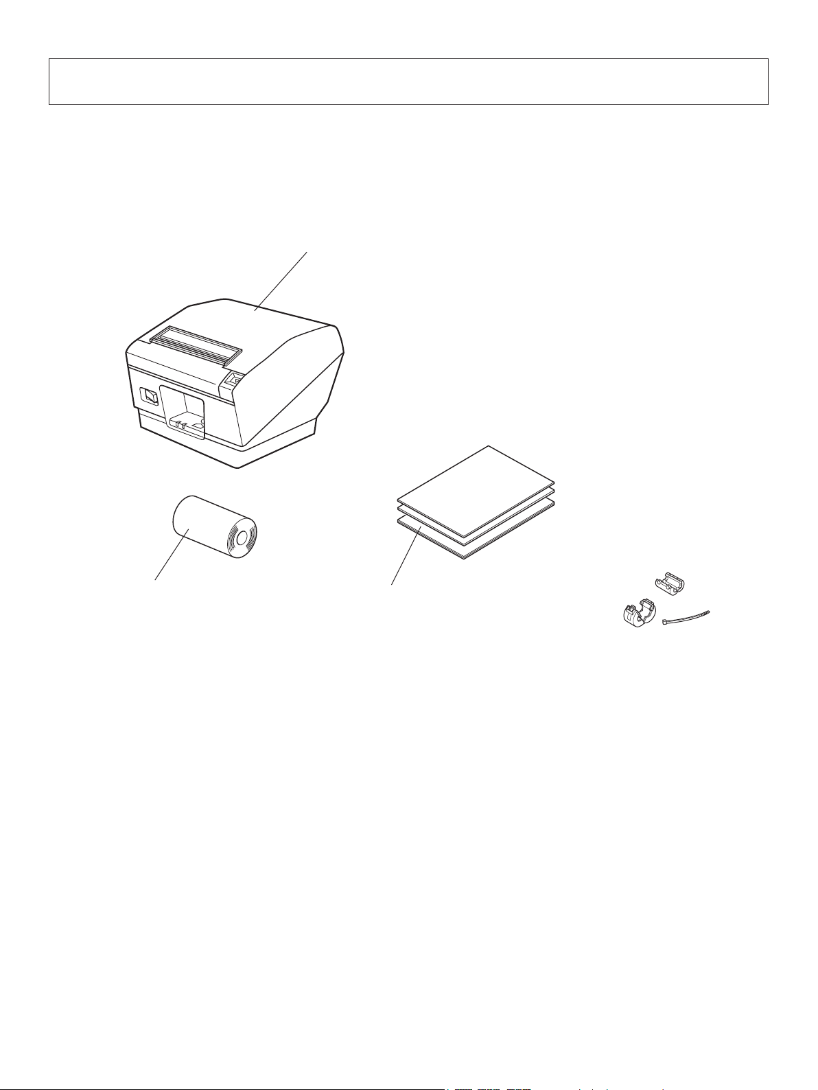
1-1. Unpacking
After unpacking the unit, check that all the necessary accessories are included in the package.
Printer
Paper roll
Setup sheets
Note
Note: The ferrite core and fastener provided with your
printer depend on your printer conguration.
Fig. 1-1 Unpacking
If anything is missing, contact the dealer where you bought the printer and ask them to supply
the missing part. Note that it is a good idea to keep the original box and all the packing materials
just in case you need to pack the printer up again and send it somewhere at a later date.
– 1 –
Page 6

1-2. Notes about Installation
1. Choose a rm, level surface where the printer will not be exposed to vibration.
2. Make sure that the printer is connected to a reliable power outlet. It should not be on the
same electric circuit as copiers, refrigerators, or other appliances that cause power spikes.
3. The power outlet you plan to connect to for power should be nearby and unobstructed.
4. Make sure that the printer is not exposed to direct sunlight.
5. Make sure that the printer is well away from heaters and other sources of extreme heat.
6. Do not locate the printer in a badly ventilated or dusty environment.
7. Make sure that the room where you are using the printer is not too humid.
8. Use the printer within the boundaries indicated in the environmental requirements. Even
when the ambient temperature and humidity are within the specications, avoid radical
changes in environmental conditions. The suitable operating temperature range is as follows:
Operating temperature: 5°C to 45°C
9. When disposing of the printer, obey local regulations.
– 2 –
Page 7
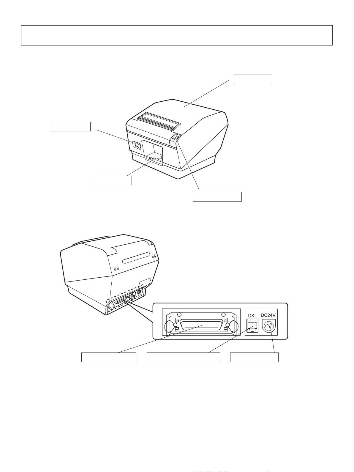
2. Parts Identication and Nomenclature
Printer cover
Open this cover to load
or replace paper.
Power switch
Used to turn on/
off power to the
printer.
Control panel
Features LED indicators to
indicate printer status and
switches to operate the printer.
Interface connector
Peripheral drive connector
Cover open lever
Push this lever in the direction of the
arrow to open the printer cover.
Power connector
For connection to a
host computer.
Connects to peripheral units
such as cash drawers, etc.
Do not connect this to a
telephone.
– 3 –
For connection of the
AC adapter.
Never unplug the
AC adapter while the
printer is on.
Page 8
3. Setup
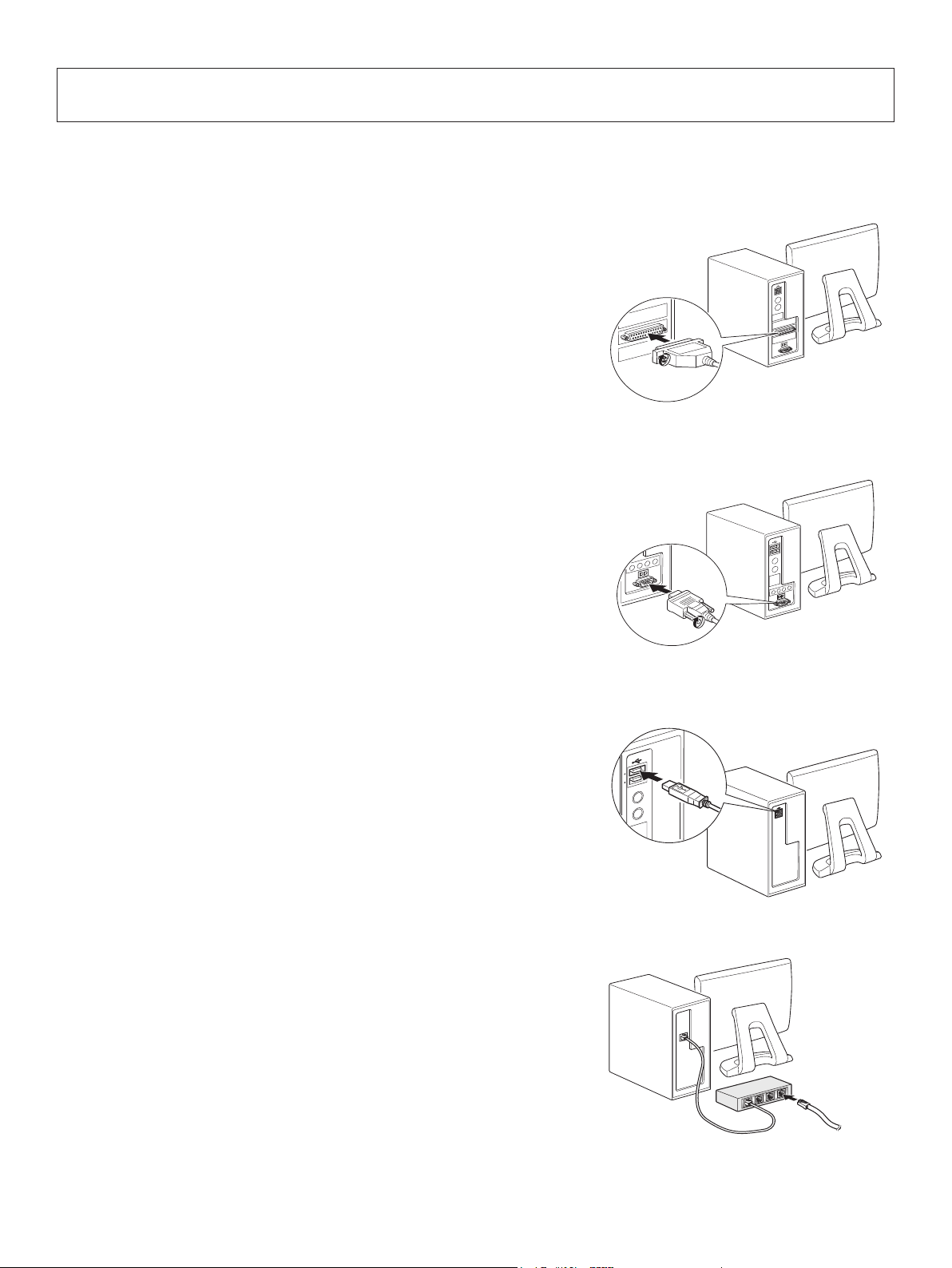
3-1. Connecting the Cable to the PC
3-1-1. Parallel Interface Cable
Connect the parallel interface cable to a parallel port
of your PC.
3-1-2. RS-232C Interface Cable
Connect the RS-232C interface cable to a RS-232C
port of your PC.
3-1-3. USB Interface Cable
Connect the USB interface cable to a USB port of
your PC.
3-1-4. Ethernet Interface cable
Connect the ethernet interface cable to a ethernet port
of your PC.
– 4 –
Page 9
3-2. Connecting the Cable to the Printer
Note that the interface cable is not provided. Please use a cable that meets specications.
CAUTION
Before connecting/disconnecting the interface cable, make sure that power to the printer and
all the devices connected to the printer is turned off. Also make sure the power cable plug is
disconnected from the AC outlet.
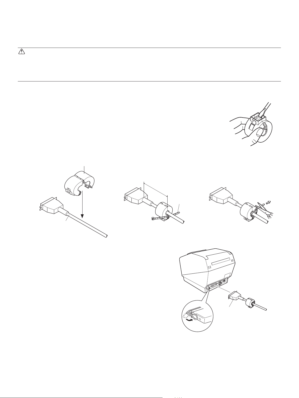
3-2-1. Parallel Interface Cable
(1) Make sure the printer is turn off.
(2) Afx the ferrite core onto the cable as shown in
the illustration.
(3) Pass the fastener through the ferrite core.
(4) Loop the fastener around the cable and lock it.
Use scissors to cut off any excess.
Ferrite core
5 cm
(maximum)
Interface cable
(5) Connect the interface cable to the connector on
the rear panel of the printer.
(6) Fasten the connector clasps.
Fastener
Parallel interface
cable
– 5 –
Page 10
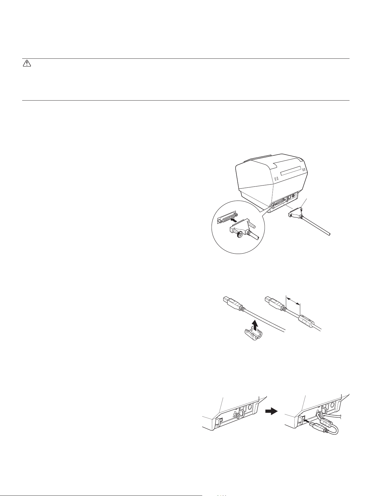
3-2-2. RS-232C Interface Cable
(1) Make sure the printer is turn off.
CAUTION
Before connecting/disconnecting the interface cable, make sure that power to the printer and
all the devices connected to the printer is turned off. Also make sure the power cable plug is
disconnected from the AC outlet.
(2) Connect the interface cable to the connector on the rear panel of the printer.
(3) Tighten the connector screws.
RS-232C
interface
cable
3-2-3. USB Interface Cable
Afx the ferrite core onto the USB cable as shown in
the illustration below and make sure to pass the cable
through the cable support as shown in the illustration.
4 cm (maximum)
– 6 –
Page 11
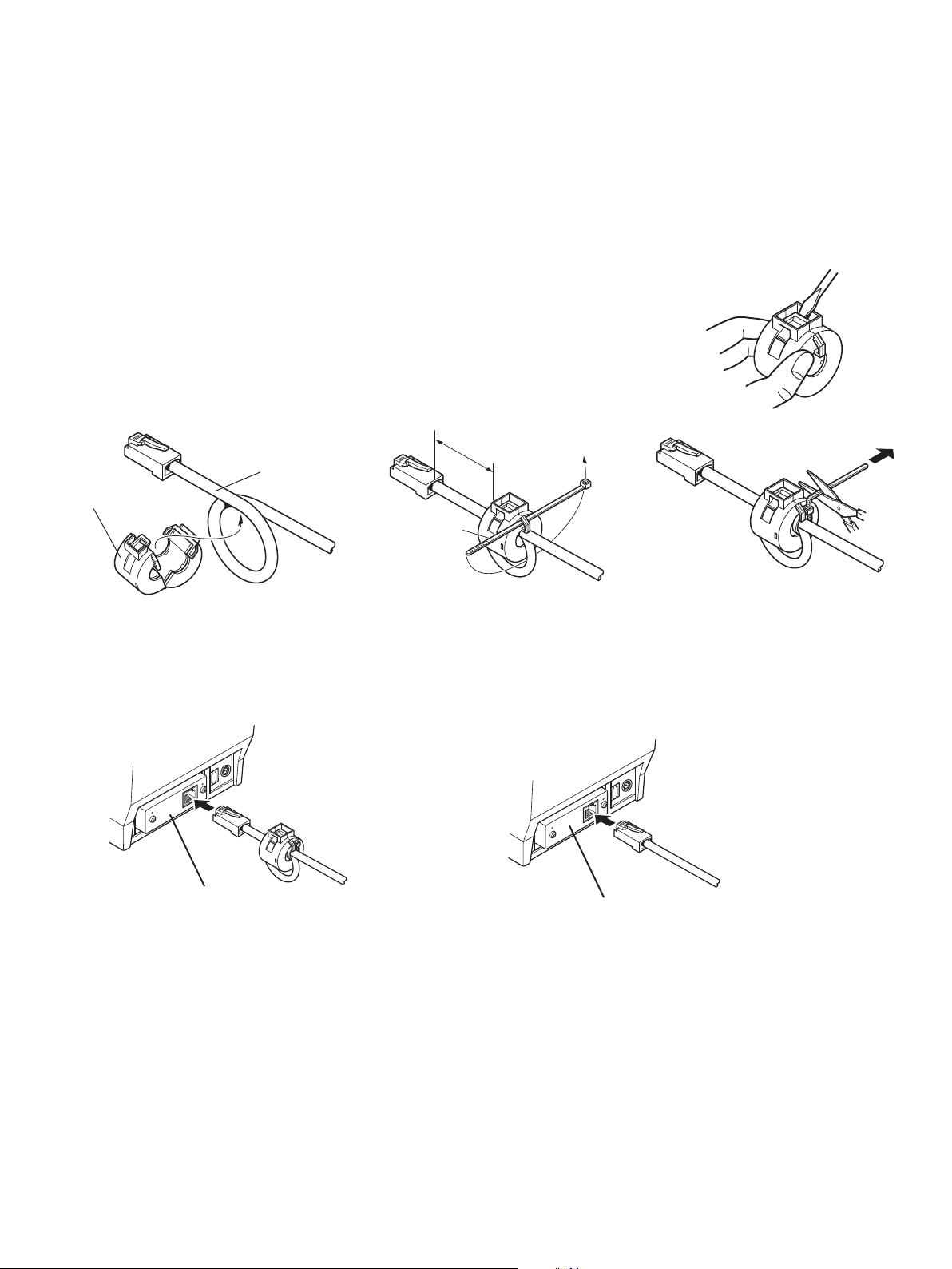
3-2-4. Connecting Ethernet Cable
If a ferrite core is included, install the ferrite core onto the Ethernet cable according to the following procedure to prevent electrical noise.
If a ferrite core is not included, perform steps (1) and (5) only.
When using an Ethernet cable that is 10 m or less, shielded cable is recommended.
(1) Make sure the printer is turned off.
(2) Install the ferrite core onto the ethernet cable as shown
in the illustration below.
(3) Pass the fastener through the ferrite core.
(4) Loop the fastener around the cable and lock it. Use scis-
sors to cut off any excess.
10 cm
(maximum)
Ethernet cable
Ferrite core
Fastener
(5) Connect the interface cable to the connector on the rear
panel of the printer.
Ethernet interface board
IFBD-HE05
Ethernet interface board
IFBD-HE07
Link disconnection detection feature
The Ethernet interface model is equipped with a link discon
nection detection feature. If the printer is turned on when an
Ethernet cable is not connected to it, the POWER and ERROR
lamps are simultaneously turned on and off at 2-second in
tervals to indicate the disconnection.
Be sure to connect the Ethernet cable from a PC or hub to the
printer, and then turn the printer on
– 7 –
Page 12
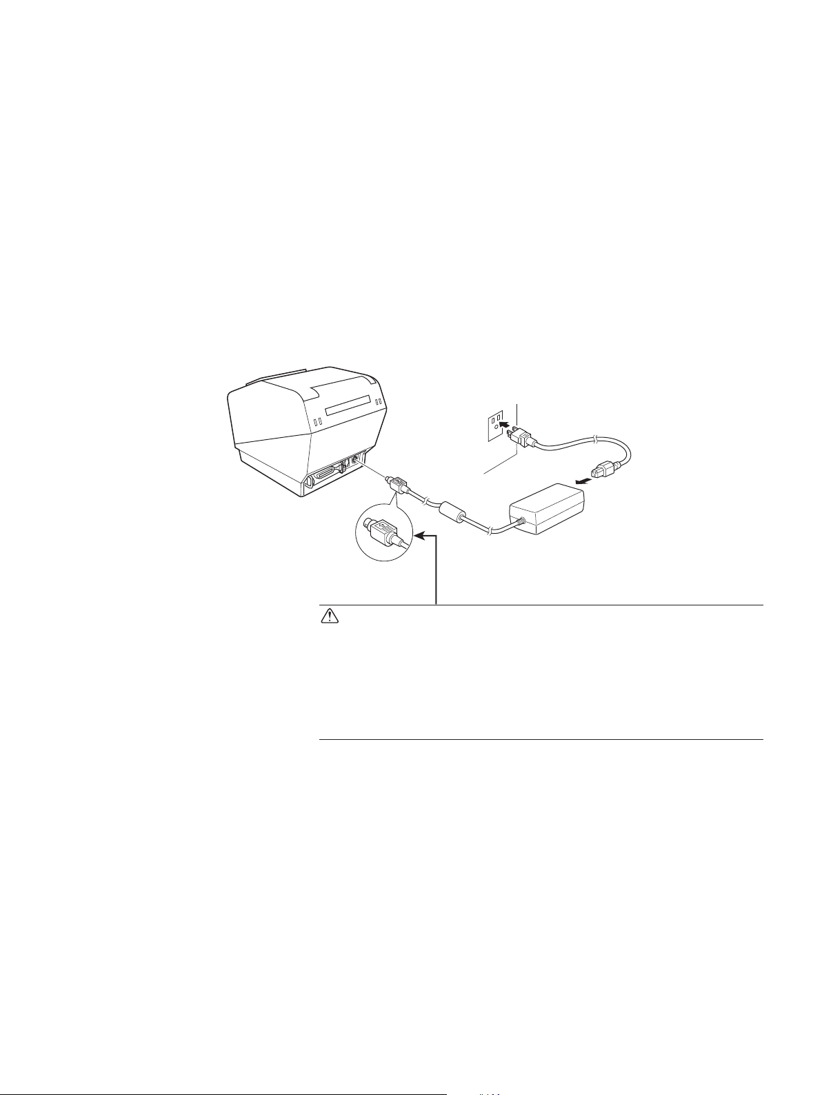
3-3. Connecting the Optional AC Adapter
Note: Before connecting/disconnecting the AC adapter, make sure that power to the printer
and all the devices connected to the printer is turned off. Also make sure the power
cable plug is disconnected from the AC outlet.
(1) Connect the AC adapter to the power cable.
Note: Use only the standard AC adapter and power cable.
(2) Connect AC adapter to the connector on the printer.
(3) Insert the power cable plug into an AC outlet.
CAUTION
When disconnecting the cable, take hold of the cable
connector to pull it out. Releasing the lock makes it easy
to disconnect the connector.
Pulling the cable excessively could cause damage to the
connector.
– 8 –
Page 13

3-4. Turning Power On
Make sure that the Power cord has been connected as described in 3-3.
Turn ON the power switch located on the front of the printer.
The POWER lamp on the control panel will light up.
Power switch
CAUTION
We recommend that you unplug the printer from the power outlet whenever you do not plan to
use it for long periods. Because of this, you should locate the printer so that the power outlet it
is plugged into is nearby and easy to access.
When an Switch blind is afxed to the printer above the power switch, the ON/OFF marks of
the power switch may be hidden. If this occurs, remove the power cord from the outlet to turn
the printer OFF.
– 9 –
Page 14

3-5. Connecting to a Peripheral Unit
You can connect a peripheral unit to the printer using a modular plug. See “Modular plug” on
page 53 for details about the type of modular plug that is required. Note that this printer does
not come with a modular plug or wire, so it is up to you to obtain one that suits your needs.
CAUTION
Make sure that the printer is turned off and unplugged from the AC outlet and that the computer
is turned off before making connections.
(1) Connect the peripheral drive cable to the connector on the rear panel of the printer.
CAUTION
Do not connect a telephone line into the peripheral drive connector. Failure to observe this may
result in damage to the printer.
Also, for safety purposes, do not connect wiring to the external drive connector if there is a
chance it may carry peripheral voltage.
– 10 –
Page 15

3-6. Loading the Paper Roll
Be sure to use paper roll that matches the printer’s specication.
1 Push the cover open lever and open the printer
cover.
For the RX model:
Turn the key under the cover open lever so that the
lock is "OPEN." Then, push down on the cover
open lever and open the printer cover.
The key cannot be removed when the lock is
"OPEN." Before you remove the key, turn it so
that the lock is in the "CLOSE" position.
Cover open lever
OPEN
Paper roll
Tension bar
2 Set the paper roll in the direction as shown, and
pull on the leading edge of the paper towards you.
CLOSE
Note: Make sure not to pass the paper under the
tension bar. In the following condition,
remove the tension bar unit in accordance
with the procedure described in paragraphs
3-6-1:
• Paper thickness between 100 μm and 150
μm
Note: When using a paper roll with an 79.5 mm
width, attach the paper roll holder in accordance with the procedure described in
paragraph 3-6-2.
3 Push both sides as shown in order to close the
printer cover.
Note: When closing the printer cover, make sure
both sides close rmly, not just one side.
– 11 –
Page 16

3-6-1. Removing the Tension Bar
When using thermal paper roll, the tension bar unit may or may not be necessary, depending
on the paper thickness. If the tension bar unit is unnecessary, remove it in accordance with the
procedure indicated below. The tension bar unit is unnecessary when using thermal label paper
roll (tack label paper).
Paper thickness
between 65 μm and 100 μm
Paper thickness
between 100 μm and 150 μm
Horizontal
Necessary
Unnecessary
Needed Optional
Vertical Kit
Needed Optional
Wall-mount Kit
Use a at head screwdriver as shown to remove the clips
at both ends of the tension bar. Then, remove the tension
bar unit.
– 12 –
Page 17

3-6-2. Removing the Paper Roll Holder
When using a paper roll with an 79.5 mm width, install the paper roll holder into the groover
as shown. When you change the effective print width (paper roll width), change the printer
utility’s memory switch setting.
For details, see the printer utility help.
Note: After using a paper roll with a width of 79.5 mm, do not change to a paper roll with
a width of 115.5 mm. This is because the printer head has deteriorated as a result of
a portion of the head having been in direct contact with the rubber roller.
Paper roll holder
– 13 –
Page 18

3-7. Bluetooth Settings
PAIR buttonRST button
(For
Bluetooth Interface Models only
)
<
LED
>
Indicates the status of the Bluetooth interface.
Green (on): Not connected.
Green (ashing): Ready to start pairing.
PAIRRST
LED
Blue (on): Connected.
Purple (ashing): Auto connection ON.
Pair the printer with the master device by following the procedure below.
Compatibility list: http://www.star-m.jp/prjump/000031.html
3-7-1. Pairing using SSP (Simple Secure Pairing) [Default]
(1) Working on the master device, tap [Settings] and set [Bluetooth] to ON.
<
iOS > < Android >
(2) After turning the printer's power switch on, press and hold the PAIR button on the rear
interface of the printer for 5 seconds or more, and then release it. The LED will ash green.
PAIR button
PAIR
RST
PAIR
RST
Flashing green LED
(3) Pairing will be possible for 60 seconds from when the LED begins ashing green.
During this time, execute "Search for devices" from the master device and tap the relevant
device from the displayed list.
Device name: Star Micronics (default)
(4) In an iOS device, after pairing, the LED will automatically begin flashing blue, and the
printer will be automatically connected. In an Android device, the LED turns blue only
while data is sent.
(5) Connect to the printer from the master device application and perform printing. If the
printing is successful, the pairing process has been completed.
– 14 –
Page 19

Note: e printer performs various processes immediately aer connecting to or disconnecting from a master
device.
Please wait approximately 0.1 seconds aer connecting, and approximately 0.5 seconds aer disconnecting,
before beginning communications with the printer.
3-7-2. Pairing using PIN code
Enter the following information in the master device if it does not support SSP, or when otherwise necessary.
PIN: 1234 (default)
Device name: Star Micronics (default)
It is recommended that you change the PIN code for greater security.
For details regard changing the PIN code, please see the “Software Manual -Star Bluetooth Utility- ”.
3-7-3. Auto Connection Function (iOS only)
Each time the wireless connection is disconnected while communicating with upper-level iOS devices including iPad over
Bluetooth, it is necessary to move back to the Bluetooth setting screen in the upper-level iOS device and tap the desired
printer name again to build a connection. is is an iOS specication.
In order to save this labor, this printer is equipped with the Auto Connection function that automatically requests a con-
nection from an upper-level iOS device that was connected to the printer last time.
e default setting of this function may dier according to the printer model you are using.
Conrm the default settings for your printer, as well as the use examples for ON/OFF settings, and then make the settings
to match your purpose.
You can also check the current ON/OFF setting by performing self-printing.
< Conrmation procedure by self-printing >
(1) While the printer cover is closed, hold down the FEED button on the
operation panel, and then turn on the power switch.
(2) Self-printing starts and the settings for F/W version, DIP switch,
memory switch, and so on are printed.
Subsequently the interface information is printed and nally the cur-
rent ON/OFF settings are printed.
Caution: If "Auto Connection function" is set to ON when using devices other than iOS, a Bluetooth communi-
cation with the printer may fail. To use devices other than iOS, such as the Android/Windows devices,
make sure you turn o the "Auto Connection" function before using the printer.
For information on how to set up this function, see "3-7-4. Setting up Auto Connection".
– 15 –
Page 20

See the table below for details of Auto Connection setting.
Auto Connection ON Auto Connection OFF
Reconnecting without
changing the master device
Changing the connected
master device
Example (recommended) When connecting directly to
After the printer is turned
on, it automatically connects
to the last master device that
was connected.
Disconnect the Bluetooth
connection in such a way as
to turn OFF the power to the
upper-level device automatically connected.
Then, establish a pairing
with a desired master device.
the printer from one master
device.
After turning on the printer,
tap this printer's name on
the Bluetooth settings screen
on the master device.
After turning on the printer,
establish a pairing with a
desired master device.
When using the printer with
multiple master device.
– 16 –
Page 21

3-7-4. Setting up Auto Connection
u
Setting up from the Main Unit for the TSP800II
Note: e following procedure explains how to change the Auto Connection function setting from ON to OFF.
If you want to change it from OFF to ON, please follow the same procedure.
(1) When paper is loaded in the printer and it is turned on, the [POWER] LED(green) on
the front of the printer turns on.
(2) If you hold down the [RST] button on the back of the printer for at more than ve seconds,
initial operations are performed in the same way as when the power is turned on, and the
LEDs on the front of the printer ash. If you press the [RST] button when the printer is
placed upright, place it horizontally again while the LED is ashing.
PAIR
RST
PAIR
RST
RST button
(3) The following information is printed. After that, turn the printer off and then back
on again to set "Auto Connection" to OFF.
< Current Setting >
Auto Connection : OFF
To enable this setting, turn
Printer Power OFF and turn ON.
(4) To make sure "Auto Connection" is set to OFF correctly, perform self-printing as
described in "3-7-3. Conrmation procedure by self-printing”.
u
Setting from the Software
After pairing your device and the TSP800II, change "Auto Connection" in the following
application provided by our company.
iOS: Download "Star Setting Utility" from the following Web site.
l
http://www.star-m.jp/prjump/000003.html
Android: Download "Star Setting Utility" from the following Web site.
l
http://www.star-m.jp/prjump/000004.html
Windows: Download "Star Bluetooth Utility" from the following Web site.
l
http://www.star-m.jp/prjump/000006.html
– 17 –
Page 22

3-7-5. Resetting Bluetooth Settings
The following procedure explains how to initialize settings that you have changed such as
the PIN code, device name, and so on.
(1) While inserting a thin object such as the tip of a pen and holding down the RST button on
the rear of the printer, turn on the printer's power switch. The POWER LED (green) and the
ERROR LED (red) on the front of the printer start flashing.
(2) Hold down the
RST button for 4 seconds or more
RST button
PAIR
RST
PAIR
RST
Hold down for 4 seconds or more
(note 1), and then release it.
(3) After you release the RST button, if the LED stops flashing and the POWER LED remains lit
green within 12 seconds, initialization is complete. If the LED continues to flash for longer than
12 seconds after releasing the RST button, this indicates that initialization was not successful.
Turn off the printer's power and then try again from step 1.
(4) Turn off the printer's power switch and delete the pairing setup with the higher ranked device.
Note 1: In step 2, if you do not hold down the RST button for long enough, initialization will not complete correctly.
For F/W Ver2.0, Ver3.0a, and Ver3.0b interfaces
In step 2, you need to hold down the RST button for 8 seconds or more.
Also, aer nishing steps 1 to 3, to check that initialization was completed correctly, perform self-printing.
If the second sheet (*** Bluetooth Information ***) is not printed, initialization has not been completed correctly. If this happens, turn o the printer's power, and then try again from step 1.
(You can check the rmware version from the self-printing results. See page 15 for the self-printing procedure.)
2: Do not turn o the printer during initialization; otherwise initialization will not complete correctly.
3: If initialization is not completed correctly, turn o the printer's power and then try again from step 1.
– 18 –
Page 23

3-8. Setup Precautions
Caution Symbol
These symbols are located near the thermal print head.
Because the thermal print head is hot immediately after printing, do not touch
it. Static electricity can damage the thermal print head. To protect the thermal
print head from static electricity, do not touch it.
This symbol is located near the cutter.
Never touch the cutter blade, as you could injure your ngers.
This symbol is located near the peripheral drive connector.
Do not connect this to a telephone.
WARNING
l
If you notice smoke or strange odors coming from this product, turn the power switch off immediately,
and remove the power cord from the AC outlet. For repairs, contact the dealer that you bought the product from.
l
Never attempt to repair the product yourself. Doing so can be dangerous.
l
Never disassemble or modify the product. Doing so may result in injury, re, or electric shock.
l
On models that have cutters or tear bars, do not touch the cutter blade or the tear bar.
-
There is a cutter or tear bar inside the paper outlet slot. Never put your hand in the slot regardless of
whether or not the printer is in operation.
-
You must open the printer cover to replace paper. However, because the cutter blade or tear bar is located inside of the cover, be careful not to bring your face and hands too close to the blade or tear bar
when the cover is open.
l
During and immediately after printing, the area around the print head is very hot. Don’t touch it because
you could be burned.
l
Be sure to turn off the printer before performing maintenance on the cutter. Failing to do so is dangerous.
CAUTION
l
We recommend that you unplug the printer from the power outlet whenever you do not plan to use the
printer for long periods.
Because of this, you should locate the printer so that the power outlet it is plugged into is nearby and easy
to access.
l
If an AC cord set is supplied with the product, the power cord that is included has been specially designed
for the product.
l
Make sure that the printer and the PC are turned off and unplugged from their AC outlets before you
make connections.
l
Do not connect a telephone line to the peripheral drive connector, which is used for devices such as cash
drawers. Doing so may cause the printer to malfunction. Also, for safety purposes, do not connect a wire
that may carry excessive voltage to the peripheral drive connector.
– 19 –
Page 24

l
Do not open the printer covers while the printer is printing or cutting.
l
Do not pull out paper when the printer cover is closed.
l
If liquid or foreign objects (such as coins and paper) enter the inside of the printer, turn the power switch
off, disconnect the power cord from the AC outlet, and consult the dealer that you bought the product from.
Continuing to use the printer may lead to a short-circuit, which may cause electric shock or re.
l
The heating element and the driver IC of the thermal print head are easily damaged. Do not touch them
with metal objects, sandpaper, etc.
l
Do not touch the thermal print head heating element. Doing so may make it dirty, which will decrease the
printing quality.
l
Static electricity can damage the driver IC and other components of the thermal print head. Avoid touch-
ing it directly.
l
Do not operate the printer if there is moisture (which has been caused by condensation or another factor)
on the front surface of the head.
l
The printing quality and the thermal print head’s service life cannot be guaranteed if paper other than the
recommended paper is used.
In particular, thermal paper containing Na+, K+, or C1- may drastically reduce the service life of the
thermal print head.
We recommend that you use paper with the following maximum ion densities: 500 ppm of Na+, 150 ppm
of K+, and 300 ppm of Cl-.
For details on recommended thermal paper, see the following webpage.
http://www.starmicronics.com/support/
CAUTION
Wireless Communication
l
Do not use the device where using wireless devices is prohibited or may cause interference or danger.
l
The radio waves generated by the device may interfere with the operation of electronic medical devices.
If you are using any electrical medical device, contact its manufacturer for the restrictions on the use of
the device.
l
Security functionality for Bluetooth is installed in this product. Congure the security settings according
to the manual (available on the Star Micronics website) to reduce the risk of security issues.
l
This device supports Bluetooth.
Since this functionality may be limited by local regulations, rst review the radio laws specic to the
country in which the product will be used.
l
Below is a list of laws this device has been approved by. As Star Micronics is committed to constant in-
novation, revisions may be made without an announcement. Access the Star Micronics website for the
latest listing of approvals.
l
Please refer to Star Micronics website for the latest information and manuals.
– 20 –
Page 25

4. Consumable Parts
When consumable parts have run out, use those specied in the table below.
Note: Access the following URL for the information of the recommended paper.
http://www.star-m.jp/eng/dl/dl02.htm
Make sure that the AC adapter specied in the table is used.
Use of consumable parts or AC adapter which are not specied in the table may result in damage to the printer, re or electric shock.
4-1. Thermal Paper Roll
(1) Paper roll specication
Width: 111.5±0.5 mm or 79.5±0.5 mm
Outer roll diameter: ø100 mm or less
Take up paper roll width: 112
Thickness: 65~150 µm (when using 115.5 mm width paper)
65~85 µm (when using 79.5 mm width paper)
Core outer/inner diameter
Paper thickness Core outer Core inner
65~75 µm ø18±1 mm ø12±1 mm
65~75 µm ø32±1 mm ø25.4 mm
75~150 µm ø32±1 mm ø25.4 mm
Printed surface: Outer edge of roll
Tail end handling: Do not use paste or glue to secure the paper roll or its core.
Do not fold the tail end of the paper.
+0.3
mm or 80
-1
+0.5
-1
mm
– 21 –
Page 26

(2) Effective Print Width
Paper Width
(mm)
Right / Left Margin (mm) Effective Print Width
(mm)
115.5 ± 0.5 4 104 69
79.5 ± 0.5 4 72 48
Left Margin Right MarginEffective Print Width
Paper Width
Number of Print Columns
(12 × 24 Font)
– 22 –
Page 27

4-2. Thermal Label Paper Roll (Tack Label Paper)
(1) Label paper specication
Backing paper width: 110±0.5 mm
Outer roll diameter: ø100 mm or less
Take up paper roll width: 112
Thickness: Max. 150 μm
Core outer/inner diameter: core inner diameter ø25.4±1 mm/core outer diameter
Printed surface: Outer edge of roll
Tail end handling: Do not use paste or glue to secure the paper roll or its
Do not fold the tail end of the paper.
(2) Effective Print Width
+0.3
mm
-1
ø32±1 mm
core.
Paper Width
(mm)
105 ± 0.5 5 95 63
Right / Left Margin (mm) Effective Print Width
(mm)
Number of Print Columns
(12 × 24 Font)
– 23 –
Page 28

• Detailed Diagrams of Recommended Tack Label Specications
Tack label
ø100 MAX
ø32 ± 1
ø25.4 ± 1
+1.5
110
-1.0
(Rolled dimension)
Release paper
(backing paper)
Base material
(label paper)
30 ±1 – 295 ±3
(Label length)
Printing direction
Black mark (back
of diagram)
PCS: 0.90 minimum
+1.0
-0.8
1
5 ± 1.0
15 MIN
35 – 300
(Black mark pitch)
• Detailed Diagram of Effective Printing Range
95 (effective printing width:
63 characters with font A)
5 (Left margin) 3 (Right margin)
Dot numbers 39 – 598
Paper tube
5 ± 1
(2.5)
105 ± 0.5
2.5 ± 0.5
Effective printing range
(Label width)
110 ± 0.5
(Backing paper width)
3 (Top margin)
* Minimum settable top margin when
3 (Bottom
margin)
paper is fed using back-feed.
105 ± 0.5 (Label width)
110 ± 0.5 (Backing paper width)
– 24 –
30 – 295 (Label length)
35 – 300 (Black mark pitch)
24 – 289 (Effective printing length)
(2.5)2.5 ± 0.5
Page 29

• Cut Position / Printing Line / Black Mark Sensor’s Positional Relationship
Effective printing range
2.5
5
Cut position
2.5
Approx. 14Approx. 14
Printing line
Black mark sensor
• Min. Label Pitch / Cut Position / Printing Line / Black Mark Sensor’s Positional Relationship
Effective printing range
(35)
30 ± 1
5 ± 1
24
Approx. 14
Approx. 14
Cut position
Printing line
Black mark sensor
– 25 –
Page 30

5. Control Panel and Other Functions
5-1. Control Panel
1 POWER lamp (Green LED)
When the printer is online, power lamp
is ON and ERROR lamp is OFF.
2 ERROR lamp (Red/Orange LED)
Indicates various errors in combination
with POWER lamp.
3 FEED button
2 ERROR lamp (Red/Orange LED)
1 POWER lamp (Green LED)
5-2. Errors
1) Recoverable errors
Error Description POWER Lamp ERROR Lamp Recovery Conditions
Head high temperature
detection
Cover open error ON ON (Red) Automatically recovered by
Paper out error ON ON (Orange) Automatically recovered by
Paper near end ON Flashes orange
Black mark paper size
error
Paper cut error OFF Flashes red lamp
Link disconnection detection*1
Flashes at 0.5-second intervals
ON ON (Orange) Recovered by loading a new pa-
Flashes at 2-second
intervals
3 FEED button
Press the FEED button to feed paper
roll.
OFF Automatically recovered after
the print head has cooled.
closing the printer cover.
loading a new paper roll, then
closing the printer cover.
Indicators show that the paper
lamp at 1 second
intervals
at 0.125 second
intervals
Flashes at 2-second intervals
end is approaching, but the
printer continues to print.
per roll, then closing the printer
cover.
Recovered if the cutter returns to
the home position after turning
the power OFF and ON. (See
Notes 1 and 2.)
Connect an Ethernet cable. For
details, see section 3-2-4, "Con-
necting Ethernet Cable."
*1 Ethernet interface model only
Note:
1) If the cutter doesn’t return to the home position or doesn’t perform the initial movement, it cannot be recovered.
2) If the paper is jammed, turn the power off, clear the jammed paper, then turn the power
ON.
– 26 –
Page 31

2) Non-recoverable errors
Error Description POWER Lamp ERROR Lamp
Flash access error OFF Flashes Orange
lamp at 0.5-second intervals
EEPROM error OFF Flashes
Red lamp at
0.75-second
intervals
SRAM error OFF Flashes Orange
lamp at 1-second intervals
Head thermistor error OFF Flashes Red
lamp at 1.5-second intervals
Power voltage error OFF Flashes Orange
lamp at 2-second intervals
Recovery Conditions
This is not a recoverable error.
This is not a recoverable error.
This is not a recoverable error.
This is not a recoverable error.
This is not a recoverable error.
Note:
1) If a non recoverable error occurs, turn the power OFF immediately.
2) When Power supply error occurs, there is a possibility that the power supply unit has
a trouble.
For other non recoverable errors, please consult the dealer for repairs.
– 27 –
Page 32

6. Adjusting the Sensor
This printer is equipped with the following two paper sensors:
PE / BM sensor
• PE and BM (Paper End and Black Mark) Sensor
Detects whether a roll paper is loaded in the printer.
In addition, detects the Black Mark that is pre-printed
NE sensor
on the paper’s print side.
• NE (Near End) sensor
Detects whether the roll paper is nearing its end.
6-1. Adjusting the Near End Sensor Position
Use the following procedure to adjust the near-end sensor so it is compatible with the size of
paper roll you are using.
However, for vertical or wall-mount use, keep the adjuster xed to level 3, without changing
its position.
1 Open the printer cover.
2 Determine the diameter of the paper roll you are using and nd the required setting in the
table below.
3 Insert the tip of a ballpoint pen or similar object into the hole of the adjuster, and then push
and side the adjuster to the desired setting.
When changing the setting, make sure that the position of the hole is aligned with the align-
ment mark indicated by the arrow.
(Level 1)
(Level 2)
(Level 3)
Near-end sensor (vertical / wall-mount layout)
(Level 3)
(Level 2)
(Level 1)
Near-end sensor (horizontal layout)
– 28 –
Page 33

Adjustment value according to the paper you are using
Paper thick-ness
(µm)
65 ø23 ø27 ø31 2.5 4.9 7.7
75 2.1 4.2 6.7
Paper thick-ness
(µm)
65 ø36 ø40 ø44 2.8 6.4 10.4
75 2.4 5.5 9.0
85 2.1 4.9 7.9
95 1.9 4.4 7.1
105 1.7 4.0 6.4
130 1.4 3.2 5.2
150 1.2 2.8 4.5
When using the paper roll with a core whose inside diameter (A):ø12, outside diameter
(B):ø18
Detected diameter (C)
(Approx. mm)
Level 1 Level 2 Level 3 Level 1 Level 2 Level 3
When using the paper roll with a core whose inside diameter (A): ø25.4, outside diameter (B):ø32
Detected diameter (C)
(Approx. mm)
Level 1 Level 2 Level 3 Level 1 Level 2 Level 3
Remained paper length
(Approx. m)
Remained paper length
(Approx. m)
C
B
A
Paper roll core
Note:
1) The adjuster is factory-set at level 1 on the horizontal
layout and level 3 on the vertical/wall-mount layout.
2) The detected diameter and remained paper length
given above are calculated values, and there may be
some variances depending on the rolled state of the
paper or the actual mechanism.
3) If thick paper is used (paper thickness between 100
μm and 150 μm), the paper roll may loosen and cause
variances in the detected values. Therefore, set the
adjustor to Level 3 for horizontal layout.
4) The near end sensor doesn't correspond to the thermal
C
label paper roll (tack label paper).
– 29 –
Page 34

6-2. PE and BM ( Paper End and Black Mark ) Sensor Adjustment
The sensitivity of the sensor is calibrated at the factory, so sensor adjustment is not necessary
under ordinary conditions. However, you may need to make adjustments when using nonrecommended paper or when the surrounding environment prevents the sensor from working
properly.
1 Make sure that the printer is turned OFF.
2 Open the printer cover, load the roll paper, and set the printer to the "paper present" state.
3 Remove the screw from the DIP switch cover on the bottom of the printer. Then take off
the DIP switch cover, as shown in the illustration below.
4 Using the tip of a ballpoint pen or a similar tool, set the DIP switches as follows:
DIP SW1-4 OFF, DIP SW1-5 ON, DIP SW1-6 ON, and DIP SW1-7 ON. Turn the printer
power ON. The lamps on the control panel will ash, and the printer will enter the sensor
adjustment mode.
5 Using a small slot screwdriver, turn VR3 as shown below, and adjust it so that the green
POWER LED and the red ERROR LED light.
6 Turn the printer power OFF, and restore the following DIP switches to their original set-
tings: DIP SW1-4, DIP SW1-5, DIP SW1-6, and DIP SW1-7.
Paper roll
DSW 2 DSW 1
9
10
VR 2
1 2 3 4 5 6 7 8 1 2 3 4
OFF
ON
VR 1VR 3
Power switch
Power lamp
ERROR
POWER
ERROR lamp
– 30 –
FEED
Page 35

6-3. NE (Near End) Sensor Adjustment
The sensitivity of the sensor is calibrated at the factory, so sensor adjustment is not necessary
under ordinary conditions. However, you may need to make adjustments when using nonrecommended paper or when the surrounding environment prevents the sensor from working
properly.
1 Make sure that the printer is turned OFF.
2 Open the printer cover, remove the roll paper and set the printer to the "paper absent" state.
3 Remove the screw from the DIP switch cover on the bottom of the printer. Then take off
the DIP switch cover, as shown in the illustration below.
4 Using the tip of a ballpoint pen or a similar tool, set the DIP switches as follows:
DIP SW1-4 OFF, DIP SW1-5 OFF, DIP SW1-6 ON, and DIP SW1-7 ON. Turn the printer
power ON. The lamps on the control panel will ash, and the printer will enter the sensor
adjustment mode.
5 Use a small slot screwdriver to turn VR2 clockwise as far as it will go. If the POWER LED
lights, go to step 6. If the POWER LED does not light, turn VR2 so that both the ERROR
LED and the POWER LED light.
6 Turn the printer power OFF, and restore the following DIP switches to their original set-
tings: DIP SW1-4, DIP SW1-5, DIP SW1-6, and DIP SW1-7.
Paper roll
Power switch
DSW 2 DSW 1
9
10
VR 2
1 2 3 4 5 6 7 8 1 2 3 4
OFF
ON
VR 1VR 3
Power lamp
ERROR
POWER
ERROR lamp
– 31 –
FEED
Page 36

7. Preventing and Clearing Paper Jams
7-1. Preventing Paper Jams
The paper should not be touched during ejection and before it is cut.
Pressing or pulling the paper during ejection may cause a paper jam, paper cutting failure or
line feed failure.
7-2. Removing Paper Jam
If a paper jam occurs, clear it as described below.
(1) Set the power switch to off to turn off power to the printer.
(2) Push the lever toward you to open the printer cover.
(3) Remove the jammed paper.
Note 1: To prevent parts such as the thermal head or the rubber roller from damage or
deformation, do not forcibly pull on the paper with the printer cover closed.
Note 2: If label paper gets jammed, the glue from the labels could stick to the parts. If this
occurs, make sure to wipe them clean of the glue.
(4) Position the paper roll straight and close the printer cover gently.
Note 1: Make sure that the paper is positioned straight. If the printer cover is closed with
the paper skewed, a paper jam may result.
Note 2: Lock the printer cover by pressing down on the sides. Do not try to close it by
pressing down on the centre. The cover may not lock properly.
(5) Set the power switch to on to turn on power to the printer. Make sure that the ERROR LED
is not lit.
Note: While the ERROR LED is lit, the printer will not accept any commands such as the
print command, so make sure that the printer cover is locked properly.
– 32 –
Page 37

8. Periodical Cleaning
Printed characters may become partially unclear due to accumulated paper dust and dirt. To
prevent such a problem, paper dust collected in the paper holder and paper transport section
and on the surface of the thermal head must be removed periodically.
Such cleaning is recommended to be carried out once six month or one million lines. If the
printer uses label paper, clean it on a monthly basis or after printing approximately 200,000 lines.
8-1. Cleaning the Thermal Head
To remove the dark paper dust that has accumulated on the thermal head surface, wipe it clean
with cotton swab (or soft cloth) dipped in alcohol (ethanol, methanol, or isopropyl alcohol). If
the printer uses label paper, wipe it clean of the glue that may have accumulated.
Note 1: The thermal head is easily damaged, so clean it with a soft cloth, taking care not
to scratch it.
Note 2: Do not attempt to clean the thermal head immediately after printing, when the
thermal head is hot.
Note 3: Beware of the risk of damaging the thermal head as a result of static electricity
that may be created during cleaning.
Note 4: Turn the power ON only after the alcohol has dried completely.
8-2. Cleaning the Rubber Roller
Use a dry, soft cloth to wipe off the dust that may have accumulated on the rubber roller.
8-3. Cleaning the Sensors and the Surrounding Areas
Clean the sensors (mainly the reector type sensors) of debris, dust, paper particles, glue, etc.
that may have accumulated.
8-4. Cleaning the Paper Holder and the Surrounding Area
Clean the paper holder of debris, dust, paper particles, glue, etc. that may have accumulated.
Sensors
Thermal head
Rubber roller
– 33 –
Page 38

English:
Deutsch:
[German]
Svenska:
[Swedish]
Español:
[Spanish]
Português:
[Portuguese]
Français:
[French]
Suomi:
[Finnish]
Italiano:
[Italian]
Dansk:
[Danish]
Nederlands:
[Dutch]
Eesti:
[Estonian]
Ελληνική:
[Greek]
Hereby, STAR MICRONICS CO.,LTD. declares that this Wireless
Device is in compliance with the essential requirements and
other relevant provisions of Directive 1999/5/EC.
Hiermit erklärt STAR MICRONICS CO.,LTD., dass sich das Gerät
Wireless Device in Übereinstimmung mit den grundlegenden
Anforderungen und den übrigen einschlägigen
Bestimmungen der Richtlinie 1999/5/EG bendet.
Härmed intygar STAR MICRONICS CO.,LTD. att denna
Wireless Device står I överensstämmelse med de väsentliga
egenskapskrav och övriga relevanta bestämmelser som
framgår av direktiv 1999/5/EG.
Por medio de la presente STAR MICRONICS CO.,LTD. declara
que el Wireless Device cumple con los requisitos esenciales y
cualesquiera otras disposiciones aplicables o exigibles de la
Directiva 1999/5/CE.
STAR MICRONICS CO.,LTD. declara que este Wireless Device
está conforme com os requisitos essenciais e outras
disposições da Directiva 1999/5/CE.
Par la présente STAR MICRONICS CO.,LTD. déclare que l'appareil
Wireless Device est conforme aux exigences essentielles et
aux autres dispositions pertinentes de la directive 1999/5/CE.
STAR MICRONICS CO.,LTD. vakuuttaa täten että Wireless
Device tyyppinen laite on direktiivin 1999/5/EY oleellisten
vaatimusten ja sitä koskevien direktiivin muiden ehtojen
mukainen.
Con la presente STAR MICRONICS CO.,LTD. dichiara che questo
Wireless Device è conforme ai requisiti essenziali ed alle altre
disposizioni pertinenti stabilite dalla direttiva 1999/5/CE.
Undertegnede STAR MICRONICS CO.,LTD. erklærer herved, at
følgende udstyr Wireless Device overholder de væsentlige
krav og øvrige relevante krav i direktiv 1999/5/EF.
Hierbij verklaart STAR MICRONICS CO.,LTD. dat het toestel
Wireless Device in overeenstemming is met de essentiële
eisen en de andere relevante bepalingen van richtlijn 1999/5/
EG.
Käesolevaga kinnitab STAR MICRONICS CO.,LTD. seadme
Wireless Device vastavust direktiivi 1999/5/EÜ põhinõuetele
ja nimetatud direktiivist tulenevatele teistele asjakohastele
sätetele.
ΜΕ ΤΗΝ ΠΑΡΟΥΣΑ STAR MICRONICS CO.,LTD. ΔΗΛΩΝΕΙ ΟΤΙ
Wireless Device ΣΥΜΜΟΡΦΩΝΕΤΑΙ ΠΡΟΣ ΤΙΣ ΟΥΣΙΩΔΕΙΣ
ΑΠΑΙΤΗΣΕΙΣ ΚΑΙ ΤΙΣ ΛΟΙΠΕΣ ΣΧΕΤΙΚΕΣ ΔΙΑΤΑΞΕΙΣ ΤΗΣ
ΟΔΗΓΙΑΣ 1999/5/EK.
Slovensky:
[Slovak]
Slovensko:
[Slovenian]
Česky:
[Czech]
Magyar:
Hungarian
[
Български:
[Bulgarian]
Polski:
[Polish]
Malti:
[Maltese]
Latviski:
[Latvian]
Lietuvių :
[Lithuanian]
Norsk :
[Norwegian]
Română :
[Romanian]
Hrvatski :
[Croatian]
STAR MICRONICS CO.,LTD. týmto vyhlasuje, že Wireless Device
spĺňa základné požiadavky a všetky príslušné ustanovenia
Smernice 1999/5/ES.
STAR MICRONICS CO.,LTD. izjavlja, da je ta Wireless Device
v skladu z bistvenimi zahtevami in ostalimi relevantnimi
določili direktive 1999/5/ES.
STAR MICRONICS CO.,LTD. tímto prohlašuje, že tento Wireless
Device je ve shodě se základními požadavky a dalšími
príslušnými ustanoveními smernice 1999/5/ES.
Alulírott, STAR MICRONICS CO.,LTD. nyilatkozom, hogy
]
a Wireless Device megfelel a vonatkozó alapvetõ
követelményeknek és az 1999/5/EK irányelv egyéb
elõírásainak.
това Безжично устройство е в съответствие със
задължителните изисквания и другите приложими
разпоредби на Директива 1999/5/EO.
Niniejszym STAR MICRONICS CO.,LTD. oświadcza, że
Wireless Device jest zgodny z zasadniczymi wymogami
oraz pozostałymi stosownymi postanowieniami Dyrektywy
1999/5/WE.
Hawnhekk, STAR MICRONICS CO.,LTD., jiddikjara li dan
Wireless Device jikkonforma mal-ħtiġijiet essenzjali u ma
provvedimenti oħrajn relevanti li hemm d-Dirrettiva 1999/5/
KE.
Ar šo STAR MICRONICS CO.,LTD. deklarē, ka Wireless Device
atbilst Direktīvas 1999/5/EK būtiskajām prasībām un citiem ar
to saistītajiem noteikumiem.
Šiuo STAR MICRONICS CO.,LTD. deklaruoja, kad šis Wireless
Device atitinka esminius reikalavimus ir kitas 1999/5/EB
Direktyvos nuostatas.
STAR MICRONICS CO.,LTD. erklærer herved at utstyret Wireless
Device er i samsvar med de grunnleggende krav og øvrige
relevante krav i direktiv 1999/5/EF.
Prin prezenta STAR MICRONICS CO., LTD. declară că acest
dispozitiv este conform cu cerinţele esenţiale și alte prevederi
relevante ale directivei 1999/5/CE.
Ovime Star Micronics CO., LTD. Izjavljuje da je bežični uređaj
u skladu s osnovnim zahtjevima i drugim važnim odredbama
direktive 1999/5/EZ.
Italia: l’uso pubblico è soggetto ad autorizzazione generale da parte del rispettivo provider di servizi.
Norge: Dette avsnittet gjelder ikke det geograske området innenfor en radius på 20 km fra sentrum av Ny-Ålesund.
is statement will be applied only for the printers marketed in Europe.
Page 39

y
,
STAR MICRONICS CO.,LTD. Head Office
20-10 Nakayoshida, Suruga-ku, Shizuoka-shi, Shizuoka, 422-8654, Japan
Tel. + 81-54-263-1111 Fax. + 81-54-263-1057
STAR Quality Technical Center
18-12 Nakayoshida, Suruga-ku, Shizuoka-shi, Shizuoka, 422-8001, Japan
Tel. + 81-54-263-1303 Fax. + 81-54-263-6650
Declaration of Conformity
We declare, under our solo r esponsibility, that the product to which this declaration
relates complies with the provisions of following European Direct ives:
1999/5/EC
2014/30/EU
2014/35/EU
2011/65/EU , 2015/863
harmonised standard
RADIO : EN 300 328 V1.9.1:2015
EMC : EN 301 489-1 V1.9.2:2011
EN 301 489-17 V2.2.1:2012
EN 55032:2012 Class B (CISPR 32:ed1.0-2012)
EN 61000-3-2:2014 (IEC 61000-3-2:2014)
EN 61000-3-3:2013 (IEC 61000-3-3:2013)
EN 55024:2010 (CISPR 24:ed2.0-2010)
SAFETY : EN 60950-1:2006 / A2:2013
EN 62311:2008
EN 62479:2010
ENVIRONMENT: EN 50581:2012
Manufacturer’s Name
Manufacturer’s Address
Star Micronics Co.,Ltd.
20-10 Naka
oshida, Suruga-ku, Shizuoka-shi
Shizuoka 422-8654 Japan
Importer’s Name
Importer’s Address
Type of Equipment
Model Name
Ref. Radio Report No.
Ref. EMC Report No.
Star Micronics Europe Ltd.
Star House, Peregrine Business Park, Gomm Road,
High Wycombe, Bucks. HP13 7DL, U.K.
Thermal Printer
TSP800
F161591E1, F161591E2
F111592E1 ,
92-152-EMC , 91-113-EMC , 91-002-16-EMC , 90-050-EMC
Ref. Safety Cert. No.
91-113-Safety ,
73507094 Rev.2,3,4,5 , S161188E1
Ref. Environ. Report No.
Place (Signature)
High Wycombe - U.K.
Date (Full Name)
Year of 1st CE mark (Position)
TSP800-RoHS-02
13-02-2017 David Pearce
'00 Technical Director
Page 40

URL: http://www.star-m.jp/eng
Rev. 1.6
 Loading...