

Page 1

Star
Manufacturing
International Inc.
10 Sunnen Drive
St. Louis, MO 63143
Installation
and
Operating
Instructions
Phone: (314) 781-2777
FAX: (314) 781-3636
COUNTER MODEL
POPCORN MACHINES
MODELS
39, 39D, 39S, 39SL
2M-Y4587 REV. B 9/30/86
REV.6-15-01RDB
1
Page 2

GENERAL INSTALLATION DATA
CAUTION
This equipment is designed and sold for
commercial use only by personnel trained
and experienced in its operation and is not
sold for consumer use in and around the
home nor for use directly by the general
public in food service locations. For
equipment to be used by the general
public, please contact the factory.
120 VOLT MACHINES
Machines with nameplate stamped 120V,
are equipped for operation on 120 Volt, 2
wire, 60 Cycle AC single phase service
and must be connected to a separate 15
Amp circuit with a 3 wire grounded,
polarized receptacle.
GENERAL OPERATING
INSTRUCTIONS
THOUROUGHLY INSPECT YOUR
MACHINE ON ARRIVAL
We do everything in our power to insure
delivery of your machine in perfect
condition. However there are instances in
which the unit may be damaged in transit.
In the event your unit is damaged in
transit, have the transportation company
make the necessary notations on your
freight bill or delivery receipt. Immediately
report this damage to the dealer from
whom you purchased the machine. The
dealer will advise proper handling
instructions. If damage is not discovered
until after delivery has been made, notify
the transportation company immediately.
However, in each instance, request an
inspection report to cover whatever damage
has occured in transit.
INSTALLATION
Each machine has been properly wired
and inspected at the Factory for operation
on the Voltage and type of Current
specified on the nameplate.
CAUTION
Do not connect to any other type of
current or the machine will be seriously
damaged.
We strongly recommend installation by a
Licensed Electrician. The guarantee of this
machine as covered by the Warranty Card
does not apply if an improper installation
has been made.
CAUTION
The motor air intake and exhaust holes
located on top of the machine must be
clear of any obstruction.
DO NOT COVER THESE AIR VENT HOLES
as serious motor damage will result.
Check to insure the installation of the
Corn Drawer before the Popping cycle is
started.
With all switches in the "OFF" position,
proceed in the following sequence to Pop
Corn:
1.) Turn "ON" the Corn Warming switch.
This switch controls the Bottom heating
element, the Top heating lamp and the
Sign diplay lamps of the Sign Lighted
models.
2.) Turn "ON" the Kettle switch. This
switch controls the Kettle heating
element. The Red pilot light is provided to
indicate when the Kettle switch is "ON".
Allow six to seven minutes to pre-heat the
Kettle. The Kettle heating element is
thermostatically controlled. Thermostat
adjustments should not be necessary as it
has been preset at the factory for the
correct popping temperature.
3.) Turn "ON" the Agitator Motor switch.
The Motor should always be running
when there is corn in the Kettle. This will
prevent scorching or burning of corn.
2
Page 3

GENERAL OPERATING
INSTRUCTIONS - continued
4.) A Corn and Seasoning measuring cup
is supplied with your machine. Pour a
level measuring cup of Oil (2 ounces) in
Kettle. Add a leveled measuring cup of raw
corn (6 ounces) and 1/2 Teaspoon of
Popcorn Salt. Vary the amount of salt and
oil to suit taste. If desired, salt may be
added adfter the Corn is popped.
5.) When the Corn stops popping, dump
the Kettle immediately by turning the
handle clockwise approximately 90
degrees to release latch. Recharge as
quickly as possible. Screen out unpopped
kernels over the perforated section of the
Corn pan.
6.) Turn the Kettle "OFF" when the
desired amount of popping is completed.
WARNING
Do not leave the Kettle and Motor switch
"ON" when the machine is not in use. Do
not immerse the Kettle in water or allow
water to come in contact with the Heating
element.
Popping Corn in dry kettle is not
recommended.
Do not connect machine to Direct Current,
as this unit is designed to operate on
Alternating Current only!
MAINTENANCE
Keep The Popping Unit Clean
After each popping period, wipe clean the
Kettle inside and out while it is warm.
This is important because if seasoning
and salt are not thoroughly removed, a
carbonized material will form. This
condition not only lowers popping
efficiency and causes excessive smoking,
but could damage the unit. For retaining
the high lustre on the stainless steel
Kettle shell and lids, use a non-abrasive
standard stainless steel cleaner when the
Kettle is cold. Use a damp cloth and a
warm mild soap solution to clean the glass
and clear plastic surfaces.
To remove Kettle:
Turn "OFF" the Kettle motor switches.
Disconnect the Twist Lock Cap at the end
of the Kettle conduit, turn Kettle handle
clockwise 90 degrees to unlatch the
Kettle, hold the Kettle and pull out the
hinge pin. The Kettle can now be removed
from unit. Use asbestos gloves to remove a
hot Kettle. DO NOT PLACE THE KETTLE
IN WATER, as this will damage the
electrical assembly.
To change Sign Display Lamps (on Sign
Lighted Models):
Turn "OFF" all switches. Unscrew 2 sheet
metal screws on the Rear side top (holding
switch and pilot light panel) and 4 screws
on the top. Cautiously take the top off.
Cahnge bulb(s) and reassemble the top
onto the frame. Tighten all six screws
securely. WARNING! Use only inside
Frosted Bulb. Wattage per label on the
surface of the Top Liner. By Authorized
Personnel Only.
MAINTENANCE and REPAIRS
Contact the Factory or one of its
representatives or a local Service
Company for Service or Maintenance
required.
3
Page 4
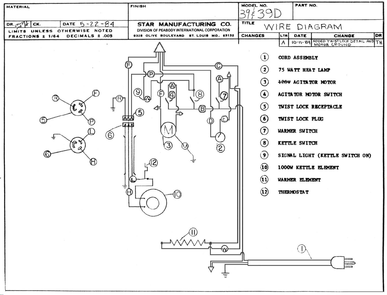
Kettle Wiring is # 14 Gage
Part Number: 1N-E2075
Cabinet Wiring is # 12 Gage
Part Number: 1N-E2052
Page 5

Page 6

Page 7

Hi-Temp Wire = 1N-E2052
Sign -”Operating Instructions”
2M-Y1755
Tag - Kettle
(Do Not Immerse)
2M-6271
Label - “Caution-Hot”
2M-Y3147
2C-Y1480
2C-Y1482
Temperature Range of Kettle = 500f to 550f
Page 8

PARTS LIST EFFECTIVE 10-13-06
PS-39408
01/31/2014 BBE
Key
Number
39 SERIES (#3955626 & BELOW)
Description
Part
Number
MODEL
Number
Per
Unit
6 Oz. Machine Parts
1 C3-39140 1 TOP ASSEMBLY COMPLETE (39) (not shown)
C3-39132 1 TOP ASSEMBLY COMPLETE (39D) No Longer Available
C3-39156 1 TOP ASSEMBLY COMPLETE (39SL) (not shown)
2 C3-Y7226 1 POPCORN SIGN (not shown)
C3-Y4590 1 POPCORN SIGN (39D) (not shown)
3 2U-Y6914 1 MOTOR w/o FAN BLADE - 120V
2U-Y6926 1 MOTOR w/o FAN BLADE - 240V
2R-Y4810 1 FAN BLADE - MOTOR
4 2E-Y5921 1 LAMP RECEPTACLE
C3-Y5920 1 LAMP CLIP (#3932007 & ABOVE)
5 2E-T1042 1 FEMALE TWIST-LOC RECEPTACLE w/o WIRES
6 2E-Y6144 3 SWITCH
7 PS-Y4556 1 BODY WRAP (#3945012 & BELOW) (20” high) (till 1991)
C3-Y6710 1 BODY WRAP (#3945013 & ABOVE) (20-1/2” high) (since 1991) NLA
2C-Y5136 4 CLIP - PUSH ON (not shown)
8-11 C3-39129 1 DOOR ASSEMBLY COMPLETE, LEFT
8 2Q-Y4547 1 DOOR w/o HARDWARE (15” x 8-3/4”) (clear only)
9 C3-39131 2 DOOR HINGE ASSEMBLY, LEFT
10 2R-Z0872 2 DOOR KNOB (#8-32) (SCREW = 2C-1493, #8-32 x 3/8)
11 C3-Y2713 2 DOOR STRIKE
12 2C-9788 1 DOOR CATCH - MAGNET
13 2J-Y6689 1 PILOT LIGHT - 120V
2J-Y6690 1 PILOT LIGHT - 240V
10,11 C3-39128 1 DOOR ASSEMBLY COMPLETE, RIGHT
14,15
14 C3-Y4547 1 DOOR w/o HARDWARE (15 x 8-3/4”)
(clear only)
15 C3-39130 2 DOOR HINGE ASSEMBLY, RIGHT
16 2S-Y4584 1 LAMP - 120V
(75W)
2S-1279 1 LAMP - DISPLAY (15W) (39SL)
(
#3935433 & BELOW)
17 2A-Y1555 1 UNIVERSAL
18 2A-5401 1 PIN - COTTER
19 2A-Y4582 1 AGITATOR SHAFT
20 C3-8318 1 AGITATOR COLLAR
21 2B-Y4581 2 AGITATOR BLADE
IMPORTANT: WHEN ORDERING, SPECIFY VOLTAGE OR TYPE GAS DESIRED
INCLUDE MODEL AND SERIAL NUMBER
Some items are included for illustrative purposes only and in certain instances may not be available.
PAGE
1 OF 4
Star Manufacturing International, Inc.
Page 9

PARTS LIST EFFECTIVE 10-13-06
Key
Number
Part
Number
MODEL
Number
Per
Unit
39 SERIES (#3955626 & BELOW)
Description
6 Oz. Machine Parts
17-21 C3-39133 1 AGITATOR ASSEMBLY COMPLETE
(TO UPDATE/UPGRADE - #3935433 & BELOW)
17 2A-Y1555 1 UNIVERSAL
18 2A-5401 1 PIN - COTTER
19 2A-Y6208 1 AGITATOR SHAFT
20 2A-Y6207 1 AGITATOR COLLAR (1-3/4”)
21 2B-Y6206 1 AGITATOR BLADE (6-1/2”)
BELOW PARTS FOR
22 C3-39102 1 KETTLE LID w/HANDLE, w/o KNOB No Longer Available
23 C3-39103 1 KETTLE LID No Longer Available
25 2R-1272 1 KNOB No Longer Available
26 C3-39118 1 KETTLE SUPPORT ASSEMBLY w/BEARING
27 2P-Y6231 1 BEARING ASSEMBLY
C3-Y4572 1 SPRING - KETTLE LID
C3-Y4575 1 SPRING - LATCH
C3-Y4576 1 RETAINER - LATCH SPRING
C3-Y4573 1 RETAINER - LID SPRING
#3945012 & BELOW
BELOW PARTS FOR
#3945013 & ABOVE
C3-39214 1 KETTLE LID (one piece)
C3-Y7230 1 CUP - MAGNET
2R-Y7229 1 MAGNET
2A-Y6915 1 GUIDE - LID
C3-39168 1 KETTLE LATCH ASSEMBLY
24 C3-Y4544 1 CORN DRAWER w/o KNOB
10 2R-Z0872 1 KNOB
28 C3-39105 1 FRONT LOWER DOOR ASSEMBLY
(18-1/4” L x 4-1/2” H, flange to flange)
29 C3-39111 1 LEAD IN CORD - 120V
(stainless steel)
C3-39123 1 LEAD IN CORD - 240V
30 2I-H7685 4 FOOT
31 2N-Y4306 1 WARMER ELEMENT - 120V (not shown)
51 2L-Y4639 1 OIL CUP (1/4 cup) (not shown)
52 2L-Y4640 1 CORN CUP (3/4 cup) (not shown)
IMPORTANT: WHEN ORDERING, SPECIFY VOLTAGE OR TYPE GAS DESIRED
53 2L-Y4916 1 CORN SCOOP (RED PLASTIC) (not shown)
INCLUDE MODEL AND SERIAL NUMBER
Some items are included for illustrative purposes only and in certain instances may not be available.
PAGE
2 OF 4
Star Manufacturing International, Inc.
Page 10

PARTS LIST EFFECTIVE 10-13-06
39 SERIES (#3955626 & BELOW)
Description
Key
Number
Part
Number
MODEL
Number
Per
Unit
6 Oz. Kettle Assembly
32-50 C3-39144 1 KETTLE ASSEMBLY COMPLETE (spun aluminum casting) N/A
32-36 C3-39126 1 KETTLE CONDUIT COMPLETE (w/wires & twist-loc plug)
32 2P-8354 1 MALE TWIST-LOC PLUG
33 C3-8355 1 CONDUIT (14”)
C3-Y3045 1 GROUND STRAP
34 2E-1177 1 SQUEEZE CONNECTOR
35 C3-39125 1 KETTLE LEAD WIRE ASSEMBLY
36 2I-5062 6 INSULATOR BEAD
2K-3831 1 BUSHING (for conduit)
37 C3-39202 1 WIRE ASSEMBLY / JUMPER
38 C3-39225 1 KETTLE CASTING ONLY (cold-rolled steel w/nickel plating)
2C-Y5137 3 STUD (10-24 x 1-5/8”)
2C-Y7271 3 STUD (10-24 x 1”)
2C-2559 6 ACORN NUT
(2 wire set w/terminals)
39 2T-6213 1 THERMOSTAT
40 2N-Y5334 1 KETTLE ELEMENT - 120V (1000W) (vendor # A65)
2N-Y4922 1 KETTLE ELEMENT - 240V (1000W)
41,42 C3-Y6611 1 ELEMENT BRACKET (NOT AS PICTURED)
2C-2560 3 NUTS - ELEMENT BRACKET
43 C3-Y4595 1 KETTLE HINGE PIN
44 2A-Y6694 1 CLIP - HAIR PIN
45-48 C3-39127 1 KETTLE HANDLE ASSEMBLY COMPLETE
45 2R-Y6762 1 KETTLE HANDLE
46 C3-Y4561 1 KETTLE ROD HANDLE
47 2P-Y4564 1 KETTLE HANDLE SPRING
48 C3-Y5378 1 CAM
49 C3-Y4928 2 KETTLE INSULATION
50 C3-39171 1 KETTLE SHELL ASSEMBLY
NEW STYLE KETTLE ASSEMBLY > NEXT PAGE
IMPORTANT: WHEN ORDERING, SPECIFY VOLTAGE OR TYPE GAS DESIRED
INCLUDE MODEL AND SERIAL NUMBER
Some items are included for illustrative purposes only and in certain instances may not be available.
PAGE
3 OF 4
Star Manufacturing International, Inc.
Page 11

2C-1827, Washer
2C-2560, Hex Head Nut
Page 12

PARTS LIST EFFECTIVE 10-13-06
Use PS-G1499, Hi-Limit Kit instead
11/22/10 BBE
Key
Number
Part
Number
MODEL
Number
Per
Unit
39 SERIES
Description
New Style - 6 Oz. Kettle Assembly
55-79 C3-39209 1 KETTLE ASSEMBLY - 120V
C3-39219 1 KETTLE ASSEMBLY - 240V
55-60 PS-39216 1 KETTLE HANDLE ASSEMBLY COMPLETE
55 2A-Y6140 1 ROD - HANDLE
56 2B-Y6139 1 CLIP - HANDLE
57 2P-Y6141 1 SPRING - HANDLE
58 2R-Y7381 1 HANDLE - KETTLE
59 C3-Y5378 1 CAM
60 2A-Y6142 1 SLEEVE - HANDLE
61-68 PS-39217 1 KETTLE CONDUIT COMPLETE
61 2A-Y6627 1 BUSHING
62 2E-1177 1 SQUEEZE CONNECTOR
63 2E-Y4967 1 WASHER
64 2K-1057 1 BUSHING, ANTI-SHORT
65 2P-8354 1 MALE TWIST-LOC PLUG
66 C3-39125 1 LEAD WIRE ASSEMBLY (2 wire set w/terminals)
2C-9617 2 WIRE TERMINAL
67 C3-Y3045 1 GROUND STRAP
68 C3-Y6634 1 CONDUIT
(w/wires & twist-loc plug)
69 C3-39208-PS 1 KETTLE ASSEMBLY - LINER
(cold-rolled steel w/nickel plating)
70 C3-39179 1 PLATE - HEAT SINK ASSEMBLY
71 2N-Y7413 1 ELEMENT - 120V
(1000W)
2N-Y7414 1 ELEMENT - 240V (1000W)
72 2T-Y7422 1 THERMOSTAT
73 C3-Y7361 3 CHANNEL - ELEMENT HOLDER
74 2A-Y7482 3 SPACER
75 C3-Y7693 1 INSULATION PAD
76 C3-Y7360 1 KETTLE SHELL
77 C3-Y7362 1 LUG / BUSS BAR
78 C3-Y9419 1 HIGH LIMIT THERMOSTAT
(230CE only)
79 C3-39233 1 WIRE ASSEMBLY (230CE only)
IMPORTANT: WHEN ORDERING, SPECIFY VOLTAGE OR TYPE GAS DESIRED
INCLUDE MODEL AND SERIAL NUMBER
Some items are included for illustrative purposes only and in certain instances may not be available.
Star Manufacturing International, Inc.
PAGE
4 OF 4
 Loading...