

Page 1
®
®
®
®
®
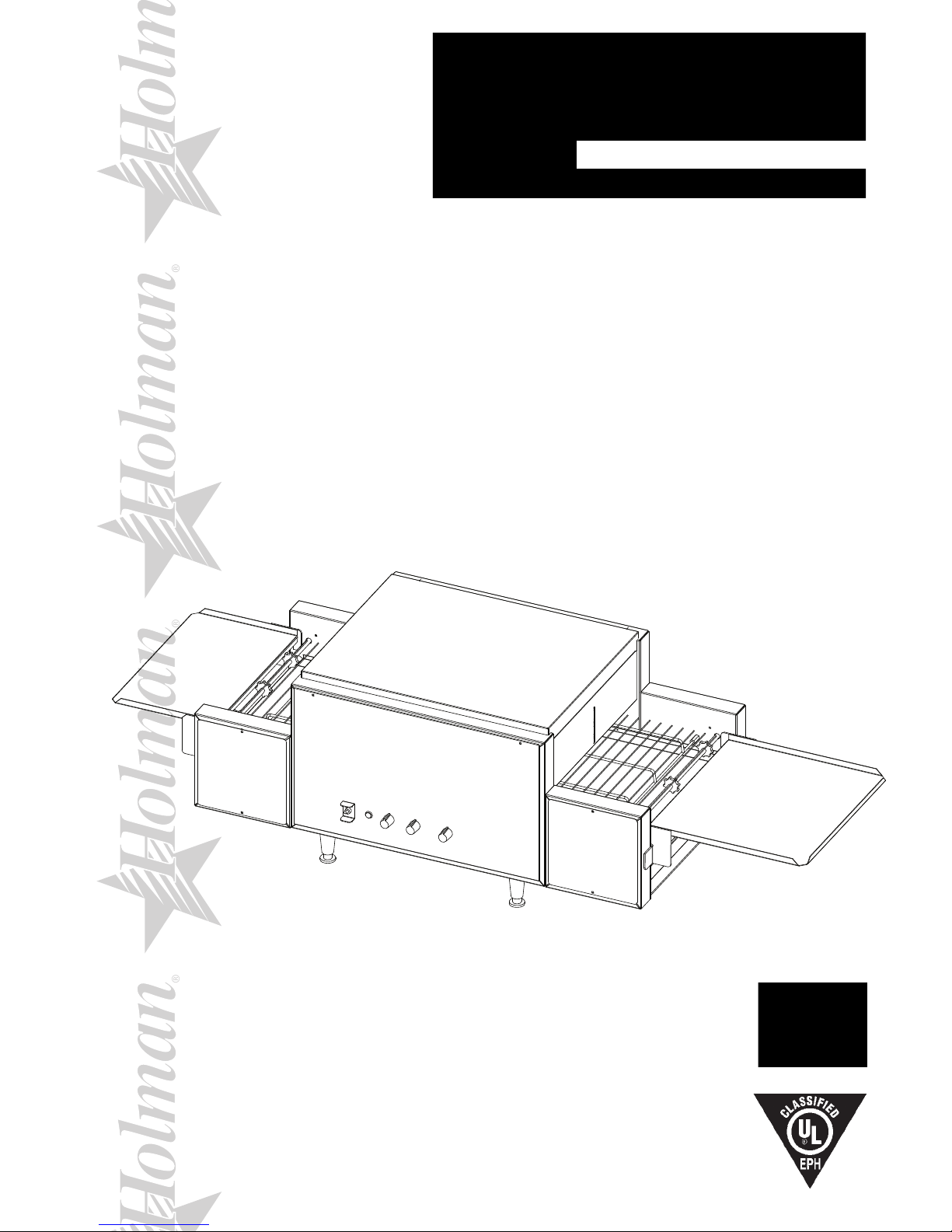
PROVEYOR
MULTI-PURPOSE OVEN
MODEL
314HX, 318HX Series
Installation and
Operation
Instructions
2M-HG0105 Rev. C 5/06/2011
314HX
1
Page 2

2
These symbols are intended to alert the user to the presence of
important operating and maintenance instructions in the manual
accompanying the appliance.
RETAIN THIS MANUAL FOR FUTURE REFERENCE
NOTICE
Using any part other than genuine Star factory supplied parts relieves the
manufacturer of all liability.
Star reserves the right to change specications and product design without
notice. Such revisions do not entitle the buyer to corresponding changes,
improvements, additions or replacements for previously purchased
equipment.
Due to periodic changes in designs, methods, procedures, policies and
regulations, the specications contained in this sheet are subject to change
without notice. While Star International Holdings Inc., Company exercises
good faith efforts to provide information that is accurate, we are not
responsible for errors or omissions in information provided or conclusions
reached as a result of using the specications. By using the information
provided, the user assumes all risks in connection with such use.
MAINTENANCE AND REPAIRS
Contact your local authorized service agent for service or required maintenance.
Please record the model number, serial number, voltage and purchase date in the area below and have it ready when
you call to ensure a faster service.
SAFETY SYMBOL
Model No.
Serial No.
Voltage
Purchase Date
Business
8:00 am to 4:30 p.m. Central Standard Time
Hours:
Telephone: (314) 684-6303
Fax: (314) 781-2714
E-mail Parts@star-mfg.com
Service@star-mfg.com
Warranty@star-mfg.com
Website: www.star-mfg.com
Service Help Desk
Authorized Service Agent Listing
Reference the listing provided with the unit
or
for an updated listing go to:
Website: www.star-mfg.com
E-mail Service@star-mfg.com
Mailing Address: Star International Holdings Inc., Company
10 Sunnen Drive
St. Louis, MO 63143
U.S.A
2
Page 3

TABLE OF CONTENTS
PAGE
Maintenance and Repairs 2
Star Contact information 2
Specications 3
General Information Data 4
Inspection & Assembly 4
Assembly and Installation 4
Heating Elements 5
Cooling System 5
Final Check 5
Electrical Connection 5
Stacking Ovens 6
Daily Operation 7
Oven Components 7
Operating Hints & Saftey 7
Cleaning 8
Maintenance Procedures 11
Troubleshooting Guide 13
Limited Equiptment Warranty 14
Wiring Diagram 15-18
Exploded View Illustration 20
Parts List 314HX 21
Parts List 318HX 22
ControlBoxConguration 23
SPECIFICATIONS
314HX
Rating/Connection: 5,400 Watts
NEMA Plug: 6-30P, 3 Phase: 6-30P
Electrical Supply: Separate service per oven - 8.7 Amp, 380/220 VAC, 3 phase, 50 Hz
Approximate Weight (314HX Oven with Legs): Installed - 86 Lbs (40 kg), Shipping - 115 Lbs (52 kg)
Dimensions: Width: 60" (152.4 cm) - Oven with Shelves
Depth: 21 1/4" (54 cm)
Height: 16 1/8" (40 cm) - Single Oven with Legs
318HX
Rating/Connection: 6,200 Watts
NEMA Plug: 6-30P, 3 Phase: 6-30P
Electrical Supply: Separate service per oven - 9.9 Amp, 380/220 VAC, 3 phase, 50 Hz
Approximate Weight (318 Oven with Legs): Installed - 96 Lbs (44 kg), Shipping - 130 Lbs (59 kg)
Dimensions: Width: 60" (152.4 cm)
Depth: 24 7/8" (63.2 cm)
Height: 16 1/8" (40 cm) - Single Oven with Legs
3
Page 4
CAUTION
GENERAL INSTALLATION DATA
This equipment is designed and sold for commercial use only by personnel trained and experienced
in its operation and is not sold for consumer use in and around the home nor for use directly by the
general public in food service locations.
Before using your new equipment, read and understand all the instructions & labels associated with
the unit prior to putting it into operation. Make sure all people associated with its use understand the
units operation & safety before they use the unit.
All shipping containers should be checked for freight damage both visible and concealed. This
unit has been tested and carefully packaged to insure delivery of your unit in perfect condition. If
equipment is received in damaged condition, either apparent or concealed, a claim must be made
with the delivering carrier.
Concealed damage or loss - if damage or loss is not apparent until after equipment is unpacked, a
request for inspection of concealed damage must be made with carrier within 15 days. Be certain to
retain all contents plus external and internal packaging materials for inspection. The carrier will make
an inspection and will supply necessary claim forms.
INSPECTION & ASSEMBLY
UNCRATING AND INSPECTING
Unpack the unit and components from the shipping container. Remove all visible packing material
andthosefrominsidethecookingchamber.Ifdamageisdiscovered,leaclaimimmediatelywith
the carrier that handled the shipment. Do not operate the unit if it was damaged during shipping.
The following should be included: Proveyor Multi-Purpose Oven, Stainless Steel Load Up & Unload
Trays, 4 Stainless Steel Legs.
CAUTION
CAUTION
REMOVE ALL HEATING ELEMENT SHIPPING SUPPORTS PRIOR TO PLACING YOUR
UNIT INTO OPERATION.
ASSEMBLY AND INSTALLATION
Theunitwasshippedwithcertainassemblyrequired,plugintoastandardoutletspeciedforits
voltageandampdraw.Ifimproperelectricalsupplyisdetermined,contactaqualiedelectricianprior
to using the unit. Removal and replacement of the power cord and plug will void the warranty. For
assistance, contact your local authorized service agent for service or required maintenance.
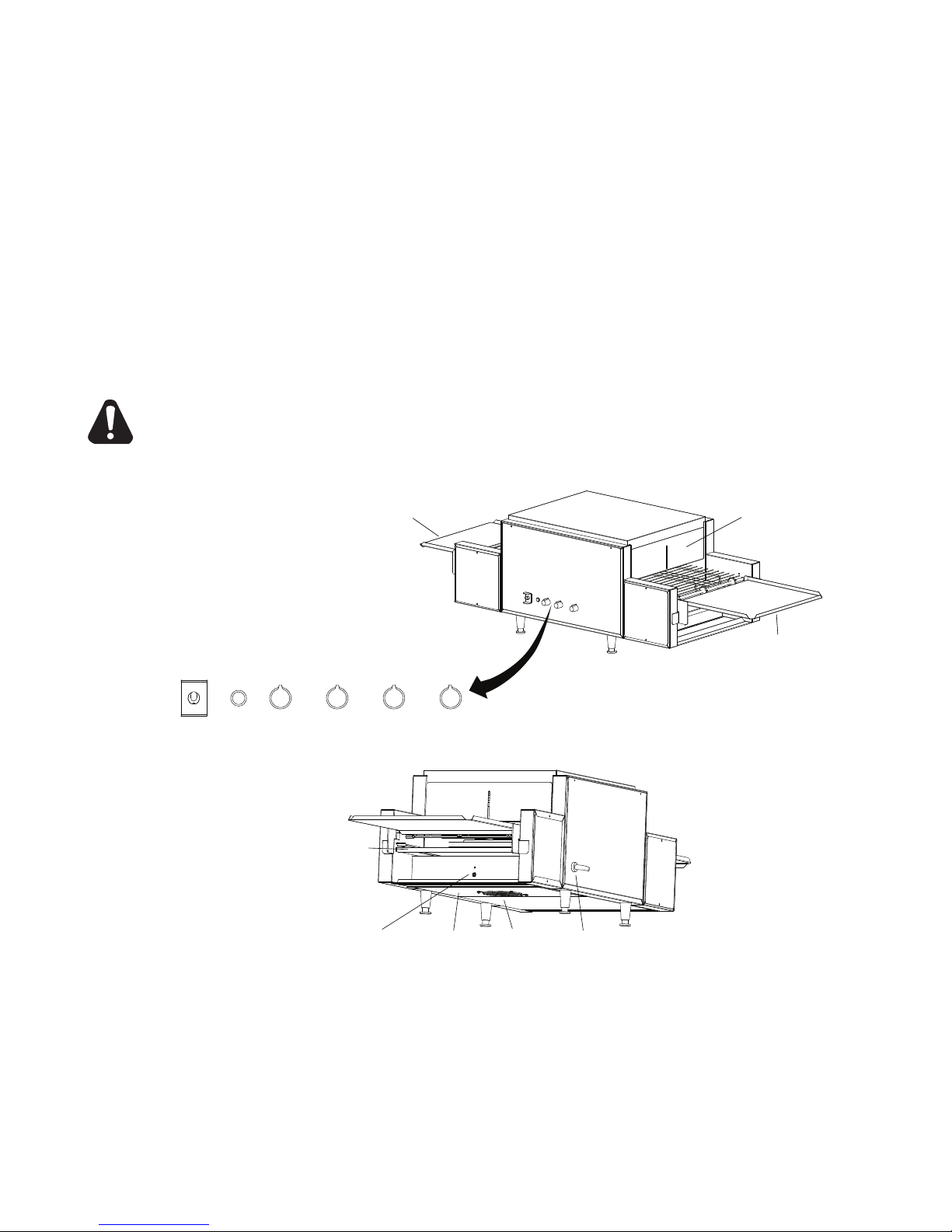
Attach the 4 legs by screwing them into the weld nuts located on the bottom of the unit. When
complete, use two people to carefully turn the unit upright. Level unit by adjusting the feet
(approximately 1/2" adjustment). Never operate unit without proper legs in place.
Beforeusingtheunitforthersttime,wipedowntheexteriorwithadampcloth.
CAUTION
Allow enough space around the oven for adequate ventilation. Do not operate the unit without the
crumb tray properly positioned. Overheating and poor baking may occur. Read all labels on the unit
and follow their instructions.
LEG INSTALLATION
4
Page 5
ASSEMBLY AND INSTALLATION continued
CLEAN
OPERATE
UNLOAD TRAY
LOAD TRAY
CRUMB TRAY
CRUMB TRAY
TYPICAL LEFT TO RIGHT CONFIGURATION
IL1001
ADJUSTABLE
HEAT SHUTTERS
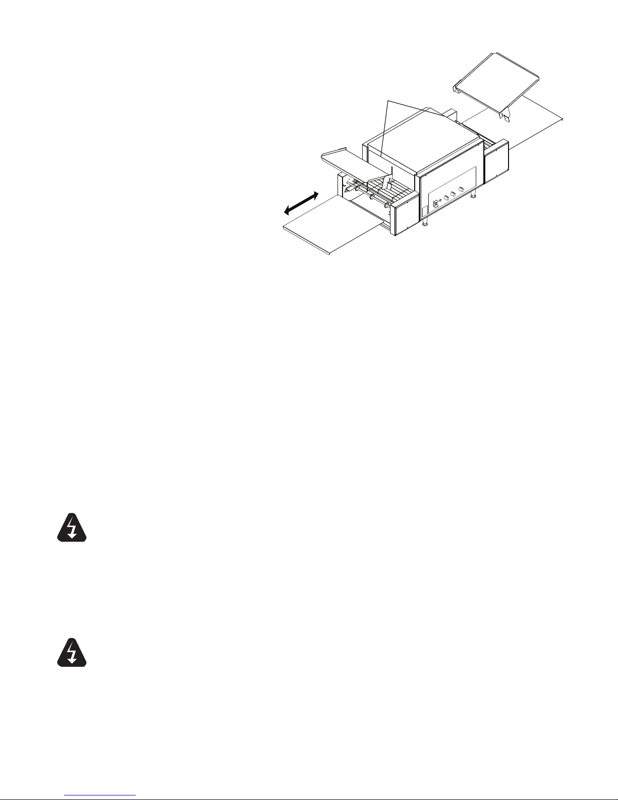
Install unit in its operating
positionallowsufcientspacefor
operating personnel. Install the
Load, Unload and Crumb Trays
as shown, making sure the ends
are at least 6" from any vertical
combustible surfaces.
Have an electrician connect input
power to the unit(s) in accordance
with local electrical codes. A
connection terminal block is inside
the left side cavity for models not
provided with a cord and plug set.
HEATING ELEMENTS
Inspect all heating elements in
the unit for breakage. Every unit
is properly tested prior to leaving
the factory, but damage may of
occurred during shipping. If a broken tube is found, do not apply power to the unit. If everything
checks out, Turn on Main Power Switch, Turn both heat controls and conveyor belt speed control to
the maximum setting and check all heater tubes and conveyor for proper operation.
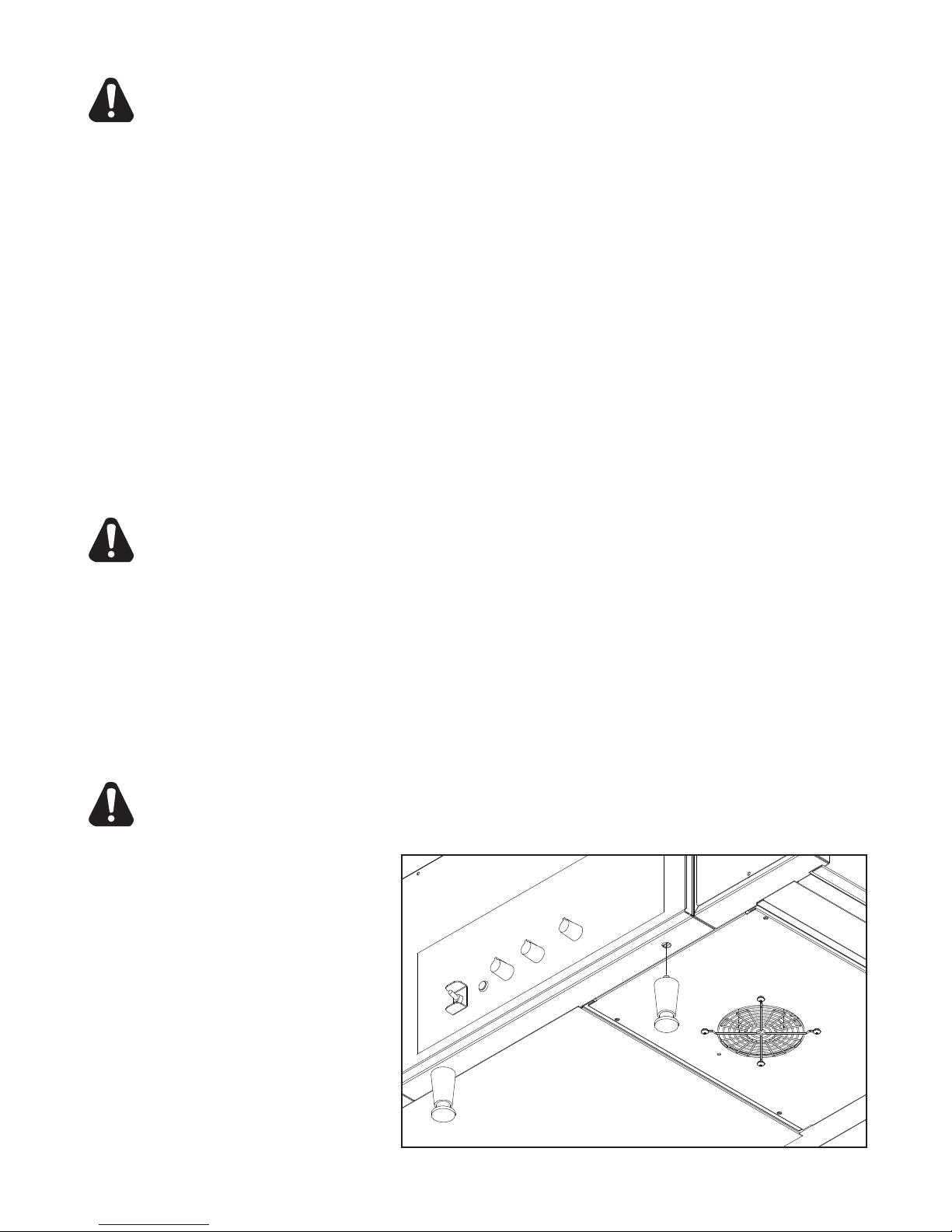
COOLING SYSTEM
After the unit is initially turned on, allow 5 to 8 minutes for the fan cooling system to come on. Once
on,checktheairintakearealocatedundertheunitandbesurethatthereisasufcientowofair
into the control box. Keep area under the unit clean from obstructions that may result in restricted air
owtothecontrolbox.Restrictingtheairowwillcausetheunittorunhotterthendesigned,causing
the Hi-Limit to turn unit off. See the Oven Components section on page 7 for control box & Hi-Limit
Reset locations.
WARNING
WARNING
FINAL CHECK
If all heaters and conveyor systems are operating properly, switch the master on/off switch to the OFF
position and allow unit to cool, the fan will continue to circulate air, cooling the unit until the internal
temperatures have been decreased.
If a problem is discovered during any of these start-up procedures, immediately switch the master
on/off switch to the OFF position
and notify the Star Service Department at (314) 634-6303.
ELECTRICAL CONNECTION
Before making any electrical connection to this unit, check that the power supply is adequate for the
voltage, amperage and requirements stated on the rating plate.
A wiring diagram is included herewith.
Disconnect the unit from the power source before installing or removing any parts.
Be absolutely sure that the ground connection for the receptacle is properly wired. Do not connect
equipment to power without proper ground connections. Improper grounding may result in personal
injury or fatality.
DO NOT CUT OR REMOVE THIS PLUG OR GROUNDING PRONG FROM THE PLUG.
CONNECT/PLUG UNIT INTO DEDICATED A.C. LINE ONLY SPECIFIED ON THE DATA
PLATE OF THE UNIT.
5
Page 6
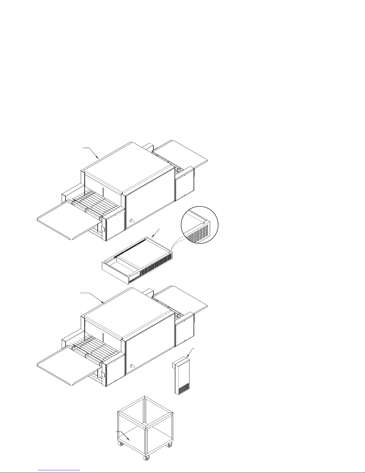
OVEN
OVEN
STACKING SPACER
EXTERNAL AIR
DUCT
EQUIPMENT
STAND
IL1020
SET-SCREW
CUT OUTS
STACKING OVENS
When stacking two Holman Proveyor Ovens a stacking spacer with an external air duct MUST be
used to prevent overheating of the control box of the top oven.
1. If a cart is to be used with units, place bottom unit on cart and align leg holes of unit with the holes
on the cart. Insert 3/8" bolts through cart and into leg holes to secure bottom unit to cart as shown
below.
2.
Place stacking spacer on top of bottom oven with internal air duct facing up and towards the rear
of the oven.
3. Mount external air duct on stacking spacer as shown below. External air duct must be installed
for cooling system of top unit to function properly.
4. Screw cap screws (Qty 4) into leg hold on the top oven.
5. Place top oven on stacking spacer. Cap screws will set into cut out in top of stacking spacer to
lock unit into position.
NOTE: Air intake of top unit must
t over the internal air duct of
stacking spacer to allow airow
into the control box of the top
oven.
TOP UNIT: cap screw, screws
into leg holes, unit sits on top of
spacer.
STACKING SPACER:
(REQUIRED)
Sits on top of bottom
oven.
EXTERNAL AIR DUCT: Mounts
onto spacer, pointing downward.
BOTTOM UNIT: Can be placed on
a counter or mounted on cart as
shown.
Cart:
Mounting
bolts for bottom
unit screw into leg holes through
the top cart frame.
6
Page 7
ADJUSTABLE HEAT SHUTTER
(QTY 2)
LOAD TRAY
UNLOAD TRAY
IL1006
ON/OFF
SWITCH
PILOT
LIGHT
UPPER
HEAT
CONTROL
LOWER
HEAT
CONTROL
CONVEYOR
SPEED
FRONT
HEAT
CONTROL
(3 Phase only)
CONTROL
BOX
HI-LIMIT
SWITCH
POWER
CORD
CRUMB
TRAY
(QTY 2)
AIR INTAKE
FAN
CAUTION
DAILY OPERATION
Baking in these units is a combination of heat and belt speed. Some foods may require more top
heat or visa versa; other foods may require low top and bottom heat and slow belt speeds. Every
product should, therefore, be tested using the separate top & bottom controls and the variable speed
control to arrive at the correct balance of heat and belt speed. When changing heat and or belt speed
setting allow approx. 5 minutes for the oven to stabilize itself at the new settings.
Check the power cord to insure that it is plugged into a proper outlet.
Always allow 10 to 15 minutes of preheat time before loading the unit with product. Failure to
allowsufcientpreheattimewillresultinunsatisfactorycookinguntiltheunitreachesoperating
temperature.
1)
Turn the master on/off switch to the ON position.
2) Set both the top and bottom heat controls to 500°F (260°C).
3-Phase Control Units, set front heat controls to 500°F (260°C)
3)
Turn conveyor speed control to the fastest setting.
4) Allow 10 to 15 minutes for initial warm up,
(5
to 8 minutes to reach adjusted temperature, once unit is fully warmed up)
CERTAIN SURFACES ARE EXTREMELY HOT DURING OPERATION AND CARE SHOULD
BE TAKEN WHILE USING THIS UNIT.
OVEN COMPONENTS
OPERATING HINTS AND SAFETY
Disconnect power to the unit with the switch at the end of each day of operation.
Do not leave the unit in operation without an attendant.
Do not leave the unit at high temperature when not in use or during idle periods. This will cause food
particlesandgreaselmtocarbonize.Itwilltakeonlyafewminutestoregainoperatingtemperature.
7
Page 8
WARNING
IL1023
CAUTION
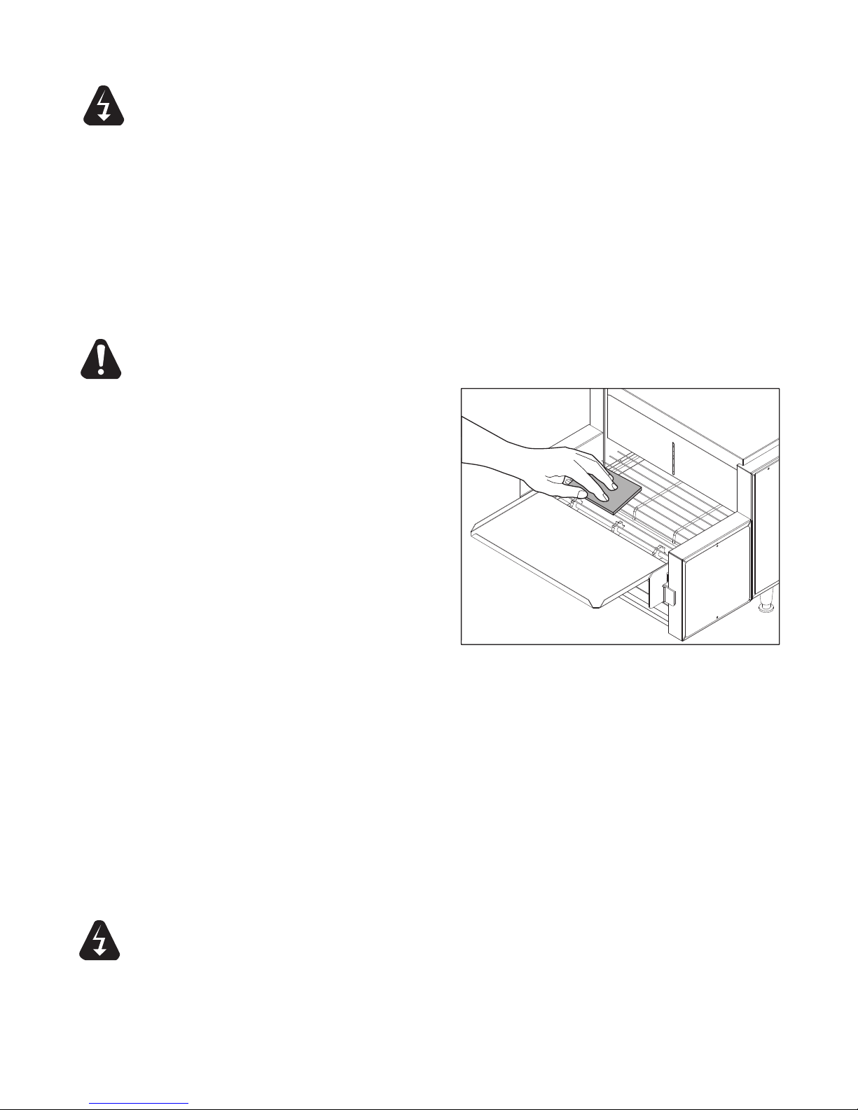
CLEANING
Preventive maintenance for your Holman Oven consists of the following recommended cleaning
procedures. To keep your oven in its top operating condition, these steps should be performed on a
daily, weekly or as indicated.
DISCONNECT UNIT FROM POWER SUPPLY OR TURN POWER OFF AT WALL
BREAKER.
DAILY
1. Turn main power switch to the OFF position. Disconnect unit from power source and
allow to cool.
2. Using a mild detergent, wipe exterior surfaces, clean with a damp cloth.
a.
For lightly soiled build-up, clean with a damp cloth.
b. For heavily soiled build-up, use an soft damp cloth and mild detergent.
DO NOT use caustic cleaners.
3. Remove
warm water.
4. Remove each crumb tray by sliding each of them out from under the conveyor belt.
Clean
DO NOT use caustic cleaners. Place trays back in place prior to putting unit back into
operation.
5. Reconnect
WEEKLY
1. T
urn main Power switch to the OFF
position. Disconnect unit from power
source and allow to cool.
2.
Perform daily cleaning procedures.
3. Using a damp cloth, wipe clean the fan
guard
under the unit.
the load & unload tray by lifting them out of position. Clean using mild detergent and
crumb trays by wiping with a damp cloth and mild detergent.
power.
located on the control box cover
WARNING
CLEAN CONVEYOR BELT
4. Reconnect power or turn power back on.
5. Switch the ON/OFF switch to the ON
position, and turn Conveyor to its fastest
setting.
6. With
7. When the Conveyor Belt is clean, take a damp cloth and wipe the conveyor, removing
8. Remove the Crumb Trays by sliding out from beneath the conveyor belt. Clean the
the Conveyor turned on and the crumb trays in place, take a wire grill brush or dry abrasive
pad, clean the exposed surface of Conveyor Belt by passing the brush or pad, back and forth
across the surface of the Conveyor Belt as the belt moves past. Continue until the entire belt is
clean. Make sure the Crumb Tray is installed, this will minimize the amount of particles that fall
into the oven.
any loose particles on the belt surface. Turn Conveyor OFF.
Crumb Trays by wiping with a damp cloth and mild detergent.
NOT use caustic cleaners.
DO
DO NOT RUN CONVEYOR OVEN WITHOUT CRUMB TRAYS INSTALLED.
CLEANING CONVEYOR BELT
DO NOT IMMERSE OR LET THE UNIT STAND IN WATER.
DO NOT HOSE DOWN THE UNIT OR THE TABLE/COUNTER IF THE UNIT IS ON THE
TABLE/COUNTER.
KEEP AWAY FROM RUNNING WATER.
8
Page 9
CLEANING CONTINUED
1.
2.
3.
IL1021
MOUNTING STUD
COUPLER
BELT SUPPORT ROD
IL1022
MONTHLY
1. Turn main power switch to the OFF position. Disconnect unit from power source and allow to
cool.
2. Perform daily & weekly cleaning procedures.
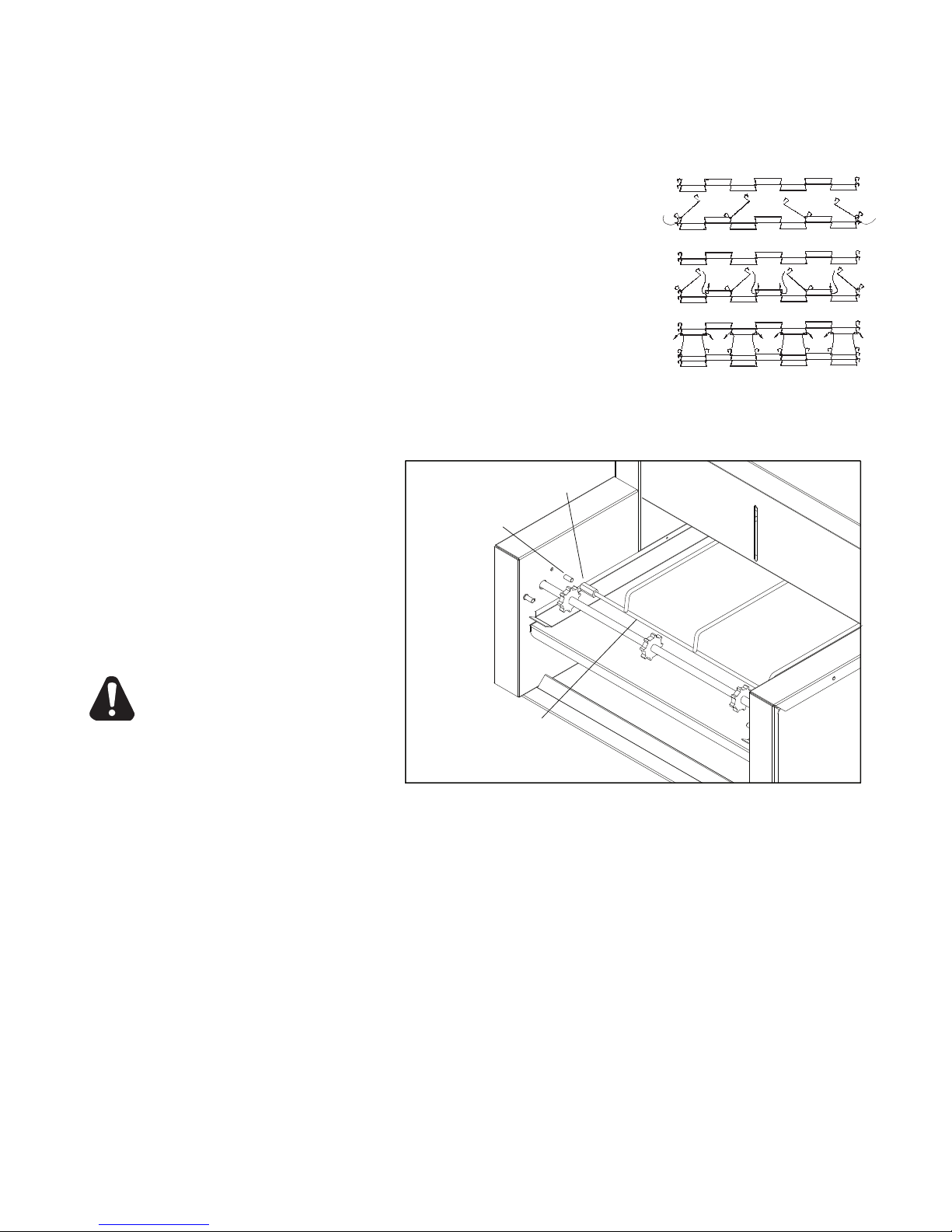
REMOVAL & CLEANING CONVEYOR BELT
3. Heavily soiled conveyor surfaces, locate the Master
on the conveyor belt. Follow the step 1 in Fig 1, to
Links
remove all of the Master Links. 314 models have 3 master
links, 318 models have 4 master links.
4. Now that the links have been un-hooked, the conveyor can
now be carefully removed from the oven. Standing at one end
of the oven. Starting with the end on the bottom, roll the
conveyor belt until it has been totally removed. Take careful
notice being sure not to damage the heater tubes.
5. Clean conveyor belt in deep sink, caustic cleaners may be
used. For a heavy soiled conveyor belt, soak over night in hot soapy water.
NOTE: DO NOT ATTEMPT TO CLEAN THE HEATER TUBES.
6. Take this opportunity to
clean and remove any
loose materials inside the
unit. Using a mild cleaner
and damp cloth, carefully
wipe the inside surfaces
being sure NOT to clean
the heater tubes. DAMAGE
CAN OCCUR TO THE
HEATER TUBES FROM
IMPROPER CLEANING.
CAUTION
DO NOT SPRAY
CLEANING SOLUTIONS
INTO OVEN CAVITY.
7. Remove the conveyor
support system as shown
in Fig 2. by removing the
Couplers from the mounting Studs. Clean by warm water and abrasive pad.
8. Reinstall the conveyor support system.
9. Reinstallconveyorbeltbyrstlayingthebeltalongthebottomoftheovencavitymaking
sure the hooks on the sides are facing the inside and the ends of the hooks will be
pointing away form the direction of the belt so not to catch on any internal components
once put back into operation.
NOTE: THE DIRECTION OF THE BELT.
10. Next, pull one end of the conveyor belt over the top of the sprockets, (being sure to line the links
up properly with the sprockets) bringing the two ends together.
11. Reinstall the previously removed master links as shown in steps 2 & 3 in Fig. 1.
12. Examinetheoventoassureproperinstallation,oncesatised,installcrumbtraysifyou
have not done so.
13. Reconnect oven to power supply and check for proper operation.
IF ASSISTANCE IS REQUIRED, CALL THE STAR SERVICE TEAM AT (314) 634-6303.
9
Page 10

MAINTENANCE PROCEDURES
IL1003
ELEMENT RETAINER
ELEMENT
IL1004
AIR INTAKE GRILL
FAN MOTOR
DRIVE MOTOR
DRIVE SPROCKET
IL1005
A. REPLACING HEATER TUBES
1) DISCONNECT POWER SOURCE.
2) Remove both the left and right side panels,
by removing the truss head screws. Pull the
top of each panel out slightly and lift up.
3) Remove heater tube wires which are requiring
replacement from its terminal block connection.
4) Remove heater tube retainer by removing
retainer screws with washer.
5) Gently, pull defective heater tube out of unit.
6) Gently, put new heater tube into unit.
7) Replace heater tube retainers.
8) Reconnect the heater tube wires to the
terminal block.
9) Install each side panel
10) Connect unit to power source and test unit for proper operation.
B. REPLACING FAN MOTOR
1) DISCONNECT POWER SOURCE.
2) After unit has cooled, remove the load &
unload trays, and turn unit over so the bottom is
facing upward.
3) Remove the control box cover which contains the fan
motor, by removing the screws.
4) Unplug power supply cord from fan motor.
5) Remove (4) screws, which hold fan motor and grill to
the control box cover and remove fan.
6) Once removed, clean grill and control box
cover using warm soapy water.
7) Put replacement motor and grill in place and secure
to the control box cover with screws
previously removed.
8) Reconnect power supply cord to fan motor.
9) Replace back panel and enclosure. Fasten with
screws removed in step 3.
10) Connect unit to power source and test unit for proper operation.
C. REPLACING BELT DRIVE MOTOR
1) DISCONNECT POWER SOURCE.
2) After unit has cooled, remove the load & unload trays,
and turn unit over so the bottom is facing upward.
3) Remove the control box cover which contains the fan
motor, by removing the (4) screws.
4) Remove the side panel that will expose the
drive chain and sprockets.
5) Remove sprocket from motor shaft, using an Allen
wrench and loosening the set-screw.
6) Remove the wire from terminal block connecting the
drive motor to the internal wiring. On units rated 208
or 240 volts, note which color leads are being used
for these connections and which lead is capped with
glass tape. The new motor should use the same arrangement.
7) Remove screws holding motor in place and remove motor from unit.
8) Put new motor in place and attach loosely with mounting screws.
9) Replace sprocket on motor shaft.
NOTE: The two sprockets must line up FLUSH with each other, so the chain does not twist any during
operation. Also the hub gets installed closets to the motor.
10
Page 11

MAINTENANCE PROCEDURES continued
IL1002
SPEED CONTROL
WASHER
INSTALLATION
LOCKING NUT
KNOB
SIDE PANEL
1/4”
10) Slide motor until the drive chain has about 1/4” slack when
lightly pushed at the center of its top open run.
See chain tensioning illustration.
11) Tighten screws to secure motor.
12) Rewire leads same as removed in step 6.
13) At this time you may plug unit in and test for proper operation prior
to reinstalling panels and turning unit back over onto its feet.
14) If unit is working correctly, turn unit off and unplug until completed
15) Reinstall side panels and control box cover.
Place unit back into its upright position.
Reinstall the load & unload trays.
16) Connect unit to power source and test unit for proper operation.
D. REPLACING SPEED CONTROL
1) DISCONNECT POWER SOURCE.
2) Remove the speed control knob and the locking
nut holding the speed control in place.
3) Remove right side panel, by removing the truss
head screws. Pull the top of the panel out slightly
and lift up.
4) Wires from the speed control go into a terminal block
located on the side of the chassis. Remove the wires
from the control and insert wires for the new speed
control into the same positions as shown on the
wiring diagram.
5) Install the washer onto the shaft of the speed control,
followed by the installation.
6) When mounting the speed control in the side panel be sure to position the anti-rotation pin in the slot as shown.
7) Tighten the speed control assembly by using the locking nut, followed by the control knob.
8) Reinstall the side panel and tighten with the screws previously removed.
Chain Tension
E. CLEANING AIR INTAKE ONCE A WEEK.
1) DISCONNECT UNIT FROM POWER SOURCE.
2) Place unit on its backside.
3) Use a vacuum cleaner and or a damp cloth to clean the air intake.
This procedure should be done at least once a week.
F. LUBRICATE THE CHAIN & SPROCKETS EVERY 6 MONTHS
1) DISCONNECT UNIT FROM POWER SOURCE.
2) Remove the side panels which exposes chain drive.
3) Using an extreme pressure, synthetic chain lubricant with a temperature range up to 400°F.
Apply liberally onto chain and sprockets.
This grease is available separately as part no. 1P-Z8914. Call 1-(800) 807-9054 to order.
4) Replace side panels, Reconnect power source and test unit.
11
Page 12

TROUBLESHOOTING GUIDE
DRIVEN SPROCKET
DRIVE SPROCKET
CHAIN
IL1007
A. UNIT WILL NOT HEAT, CONVEYOR BELT WILL NOT MOVE.
1) Be sure the main circuit breaker is switched to the ON position and there is power to the outlet.
2) Check to see if the oven is plugged in and all controls are turned to the ON position.
3) Be sure the Hi-Limit Reset Button is pushed in.
4) Call the Star Service Help Desk at (314) 634-6303.
B. UNIT WILL NOT HEAT, CONVEYOR TURNS PROPERLY.
1) Check to see if the top and bottom heat controls have been turned to the maximum setting.
2) Press the Hi-Limit Reset Button located underneath the conveyor belt on the right side. If this reactivates
the heater tubes, see Hi-Limit Reset Section below.
3) Call the Star Service Help Desk at (314) 634-6303.
C. HI-LIMIT (HEAT) RESET.
Your Holman conveyor oven is equipped with an automatic activated temperature limit switch which interrupts the
heater tube connections if the air temperature in the control box exceeds 190°F (88°C) This limit switch can be
reset manually by pushing the button in the center of the switch which is located on the right side under the
conveyor belt. See Oven Components on Page 7 for location. Unit will not reset until internal temperature has
fallen below 190°F (88°C).
NOTE: THE HI-LIMIT SWITCH CAN BE ACTIVATED IF THERE IS NOT A PROPER AMOUNT OF
AIR FLOW BEING GENERATED BY THE COOLING FAN. IF THIS OCCURS:
1) DISCONNECT UNIT FROM POWER SOURCE.
2) Check to see if the air intake area (center of the control box, bottom of unit) is free of dust,
grease or other obstructions.
3) Checktoseeifcrumbtrays(heatreectors)areinplace.IftheHi-LimitSwitchcannotbereset,callthe
Star Service Help Desk at (314) 634-6303.
NEVER OPERATE UNIT WITHOUT CRUMB TRAYS IN POSITION AS THIS CAUSES
CAUTION
OVERHEATING IN THE CONTROL BOX.
D. CONVEYOR WILL NOT TURN, UNIT HEATS PROPERLY.
To check for mechanical binding:
1) DISCONNECT UNIT FROM POWER SOURCE.
2) Check to see if there are obstructions in the conveyor
system that may cause a jam. If so, remove obstruction.
3) Check power supply & terminal blocks for loose or
disconnected wires.
4) Remove right side panel and drive motor sprockets,
see illustration. Manually move conveyor belt to check
for mechanical binding. If conveyor belt moves freely,
call the Star Service Help Desk at (314) 634-6303.
The drive motor or speed control may have to be replaced.
E. CONVEYOR TURNS AT ONE SPEED
REGARDLESS OF SPEED CONTROL SETTING.
1) Call the Star Service Help Desk at (314) 634-6303, as speed control MAY need replacing.
Refer to REPLACING SPEED CONTROL in the previous section.
F. COOLING FAN DOES NOT START
1) Remove control box cover and check fan blade for obstruction.
2) Check electrical connections are secure and complete.
3) Call the Star Service Help Desk at (314) 634-6303, as the fan switch and or fan motor MAY need
replacing.
Refer to REPLACING FAN MOTOR in the previous section.
12
Page 13

2M-4497-2 10/2010
The foregoing warranty is in lieu of any and all other warranties expressed or implied and constitutes the entire warranty.
FOR ASSISTANCE
Should you need any assistance regarding the Operation or Maintenance of any Star equipment; write, phone, fax or email our Service Department.
In all correspondence mention the Model number and the Serial number of your unit, and the voltage or type of gas you are using.
ALL:
* Pop-Up Toasters
* Butter Dispensers
* Pretzel Merchandisers
(Model 16PD-A Only)
* Pastry Display Cabinets
* Nacho Chip Merchandisers
* Accessories of any kind
* Sneeze Guards
* Pizza Ovens
(Model PO12 Only)
* Heat Lamps
* Pumps-Manual
Visit our Website at: www.star-mfg.com Email: service@star-mfg.com
THOROUGHLY INSPECT YOUR UNIT ON ARRIVAL
This unit has been tested for proper operation before leaving our plant to insure delivery of your unit in perfect condition. However, there are instances in
which the unit may be damaged in transit. In the event you discover any type of damage to your product upon receipt, you must immediately contact the
transportation company who delivered the item to you and initiate your claim with same. If this procedure is not followed, it may affect the warranty status of
the unit.
LIMITED EQUIPMENT WARRANTY
All workmanship and material in Star products have a one (1) year limited warranty on parts & labor in the United States and Canada. Such warranty is limited
to the original purchaser only and shall be effective from the date the equipment is placed in service. Star's obligation under this warranty is limited to the repair
of defects without charge, by the factory authorized service agency or one of its sub-agencies. Models that are considered portable (see below) should be taken
to the closest Star service agency, transportation prepaid.
> Star will not assume any responsibility for loss of revenue.
> On all shipments outside the United States and Canada, see International Warranty.
* The warranty period for the JetStar six (6) ounce & Super JetStar eight (8) ounce series popcorn machines is two (2) years.
* The warranty period for the Chrome-Max Griddles is ve (5) years on the griddle surface. See detailed warranty provided with unit.
* The warranty period for Teon/Dura-Tec coatings is one year under normal use and reasonable care. This warranty does not apply if damage occurs to
Teon/Dura-Tec coatings from improper cleaning, maintenance, use of metallic utensils, or abrasive cleaners, abrasive pads, product identiers and
point-of-sale attachments, or any other non-food object tha comes in continuous contact with the roller coating. This warranty does not apply to the
“non-stick” properties of such materials.
> This warranty does not apply to "Special Products" but to regular catalog items only. Star's warranty on "Special Products" is six (6) months on parts
and ninety (90) days on labor.
> This warranty does not apply to any item that is disassembled or tampered with for any purpose other than repair by a Star Authorized Service Center or
the Service Center's sub-agency.
> This warranty does not apply if damage occurs from improper installation, misuse, wrong voltage, wrong gas or operated contrary to the Installation and
Operating instructions.
> This warranty is not valid on Conveyor Ovens unless a "start-up/check-out" has been performed by a Factory Authorized Technician.
PARTS WARRANTY
Parts that are sold to repair out of warranty equipment are warranted for ninety (90) days. The part only is warranted. Labor to replace the part is chargeable to
the customer.
SERVICES NOT COVERED BY WARRANTY
PORTABLE EQUIPMENT
Star will not honor service bills that include travel time and mileage charges for servicing any products considered "Portable" including items listed below.
These products should be taken to the Service Agency for repair:
1. Travel time and mileage rendered beyond the 50 mile radius limit
2. Mileage and travel time on portable equipment (see below)
3. Labor to replace such items that can be replaced easily during a daily cleaning
routine, ie; removable kettles on fryers, knobs, grease drawers on griddles, etc.
4. Installation of equipment
5. Damages due to improper installation
6. Damages from abuse or misuse
7. Operated contrary to the Operating and Installation Instructions
8. Cleaning of equipment
9. Seasoning of griddle plates
10. Voltage conversions
11. Gas conversions
12. Pilot light adjustment
13. Miscellaneous adjustments
14. Thermostat calibration and by-pass adjustment
15. Resetting of circuit breakers or safety controls or reset buttons
16. Replacement of bulbs
17. Replacement of fuses
18. Repair of damage created during transit, delivery, &
installation OR created by acts of God
* The Model 510FD Fryer.
* The Model 526TOA Toaster Oven.
* The Model J4R, 4 oz. Popcorn Machine.
* The Model 518CMA & 526CMA Cheese Melter.
* The Model 12MC & 15MC & 18MCP Hot Food Merchandisers.
* The Model 12NCPW & 15NCPW Nacho Chip/Popcorn Warmer.
* All Hot Dog Equipment except Roller Grills & Drawer Bun Warmers.
* All Nacho Cheese Warmers except Model 11WLA Series Nacho Cheese Warmer.
* All Condiment Dispensers except the Model HPD & SPD Series Dispenser.
* All Specialty Food Warmers except Model 130R, 11RW Series, and 11WSA Series.
* All QCS/RCS Series Toasters except Model QCS3 & RCS3 Series.
* All Fast Steamer Models except Direct Connect Series.
13
Page 14

®
MODEL:
314HX, 318HX, 208/240V, 3 PHASE, DELTA CONF
THIS DRAWING CONTAINS INFORMATION CONFIDENTIAL TO STAR MFG. INT'L. INC.
NO REPRODUCTION OR DISCLOSURE OF ITS CONTENTS IS PERMITTED.
820134 Rev A
7/15/2004
Red Red
Blk
Blk
Brn Brn
Brn
Brn
Brn
Brn
Brn
Brn
Brn
Brn
Brn
Blk
Blk
Blk
Blk
Blk
Blk
Red
Red
Red
Red
Blk
Blk
Blk
Blk
Blk
Blk
Yel
Yel
Pur
Pur
Ong
Yel
Yel
A
FRONT HEAT
TOP HEAT
BOTTOM HEAT
FRONT
TOP
BOTTOM
SPEED
CONTROL
FAN
CONTROL
SWITCH
ON/OFF
PILOT
LIGHT
HIGH LIMIT
RESET
MAIN POWER
L1
L2
L3
G
MOTOR
CONV.
HEAT
PROBE
TOP
CONTROL
HEAT
FRONT
BOTTOM
CONTROL
HEAT
HEAT
TOP
CONTROL
FRONT
PROBE
HEAT
PROBE
HEAT
BOTTOM
FAN
MOTOR
M
M
L
T
A
1
2
33
2
1
14
Page 15

®
MODEL:
314HX, 318HX, 208/240V, SINGLE PHASE
THIS DRAWING CONTAINS INFORMATION CONFIDENTIAL TO STAR MFG. INT'L. INC.
NO REPRODUCTION OR DISCLOSURE OF ITS CONTENTS IS PERMITTED.
820078 Rev A
08/16/2001
RED
ORG
BLU
BRN
ORG
ORG
PUR
BRN
BRN
BRN
BRN
BRN
BRN
RED
YEL
RED
YEL
ORG
PUR
YEL
ORG
PUR
BLK
YEL
ORG
PUR
YEL
BLK
RED
BLK
BLK
BLK
RED
BLK
YEL
BLK
BLK
BLK
RED
BLK
BLK
YEL
RED
BLK
15
Page 16

®
MODEL:
314HX, 318HX, 208/220/240 VOLT, 60 Hz
SINGLE PHASE (PHASE CONTROLS)
THIS DRAWING CONTAINS INFORMATION CONFIDENTIAL TO STAR MFG. INT'L. INC.
NO REPRODUCTION OR DISCLOSURE OF ITS CONTENTS IS PERMITTED.
020078 Rev -
05/2/2000
ORN
BLU
RED
BLK
BLK
PUR
BRN
BLK
RED
RED
BLK
BLK
YEL
YEL
RED
RED
BLU
BLK
ORN
ORN
YEL
PUR
BLK
16
Page 17

115394
MAIN POWER
G
N
L3
L2
L1
CONV.
MOTOR
HIGH LIMIT
RESET
135100
SPEED
CONTROL
FAN
LIGHT
PILOT
CONTROL
ON/OFF
SWITCH
BOTTOM HEAT
TOP HEAT
FRONT HEAT
BLK
RED
BLU
BRN
BRN
PROBE
HEAT
CONTROL
CONTROL
HEAT
FRONT
TOP
CONTROL
HEAT
BOTTOM
FRONT
HEAT
200556
BOTTOM
FRONT
TOP
PROBE
PROBE
HEAT
BOTTOM
HEAT
TOP
115392
BLK
RED
RED
RED
BLK
BLK
BRN
BRN
BRN
ORG
ORG
BRN
ORG
BRN
BRN
BRN
YEL
PUR
YEL
PUR
YEL
PUR
RED
RED
RED
RED
BLK
BLU
BLK
®
MODEL:
314HX, 318HX, THREE PHASE WYE CONF.
(STRATFORD CONTROLS)
THIS DRAWING CONTAINS INFORMATION CONFIDENTIAL TO STAR MFG. INT'L. INC.
NO REPRODUCTION OR DISCLOSURE OF ITS CONTENTS IS PERMITTED.
820145 Rev B
10/22/2004
M
M
BLK
ORG
BLU
BRN
YEL
BLK
RED
YEL
BRN
BLU
BLK
BLK
17
Page 18

Control Box View
Page 23
MODEL: PROVEYOR
314HX, 318HX, 418HX
SK2145 Rev. A 9/14/09
1
1
2
3
4
5
7
8
9
10
12
13
11
14
15
16
16
17
19
18
50
20
21
22
42
43
44
45
10
23
24
25
26
28
29
30
31
32
34
35
36
37
33
38
39
40
41
NAMEPLATE
6
Page 19

208V
208V
240V/50/
3PH
STRATFORD
240V/50/3PH
Part No Qty Description App.
Fig
GD-197888
No
HEATERTUBE, QUARTZ
GD-197893 220V
HEATERTUBE, METAL
9
GD-197889 240V
2N-209201
29
RETAINER, SINGLE HEATERTUBE, QUARTZ
RETAINER, DUAL HEATERTUBES, QUARTZ
1
4
HZ-114240 240V30GD-402446
GD-401238 RETAINER, SINGLE HEATERTUBE, METAL31GD-401232
GG-401989 RETAINER, HEATERTUBES, METAL
32 2E-200564 1 SWITCH, ON/OFF TOGGLE 314HX
33 2P-401780 1 GUARD, TOGGLE
SWITCH, FRNT HEAT CNTRL POT., STRAT. 3 Phase
2J-200567
34 2E-200180 3 INSULATION, SWITCH, POT.
SWITCH, CONTROL HEAT ASSY TOP,
PHASE CONTROL
1
2J-200567 SWITCH, TOP HEAT CNTRL POT., STRAT
GD-115350
35
SWITCH, BTM HEAT CNTRL POT., STRA CNT
1
2J-200567
GD-115351 SWITCH, CNTRL HEAT ASSY BTM, PHASE
36
37 GB-118062 1 SWITCH, SPEED CONTROL ASSY (1000Ω) 314HX
CAP, KNOB CONTROL
3
2R-200708
38 2J-200427 1 PILOT LIGHT
314HX
314HX Series Holman Conveyor Oven
KNOB, HEAT CONTROL, SPEED CONTROL
LABEL 3 PHASE HX CONTROL LABEL 3 Phase
4 3 Phase
3
4 3 Phase
1
1 PANEL, CONTROL SIDE
2R-200768
2M-200866
2M-200872 LABEL, CONTROL PANEL41GD-401375
GD-401540 3 Phase
39
40
42 2U-200561 1 MOTOR, FAN
43 HT-401496 1 COVER, CONTROL BOX
44 2R-200562 1 GRILL, FAN MOTOR
45 2C-200048 4 SCREW, SLOT HEX 10-24 X 1/2
2 CONTROL, HEAT (Stratford Control)
3 CONTROL, HEAT (3 PHASE) 3 Phase
46 2J-200569
47 SP-115146 1 SWITCH, HIGH LIMIT RESET
NI = NOT ILLUSTRATED
Part No Qty Description App.
1 GD-401227 2 TRAY, CRUMB
2 2A-200672 4 COLLAR, SHAFT
3 GD-100707 1 RACK, BELT SUPPORT SYSTEM
4 GD-100403 1 TRAY, LOAD-UP
5 GD-160008 1 CONVEYOR BELT (14” X 75”)
6 2B-200626 3 LINK, MASTER, CONVEYOR BELT
7 GD-401168 1 COVER, TOP
8 2A-200284 3 E-CLIP
No
Fig
9 2C-200149 3 WASHER
11 GD-101253 1 SHAFT, IDLER (3/8”)
10 GB-112262 4 BUSHING 3/8”
12 2E-200574 1 SWITCH, FAN MOTOR
13 HG-402144 1 FAN SWITCH BRACKET
PROBE, HEAT (Stratford Control Model)
2
14 GD-401238 1 RETAINER, HEATER TUBE RIGHT
15 2J-200568
PANEL ASSY, PLUG SIDE (L-R MODEL)
3 3 Phase
1
GD-101488
GD-101489 PANEL ASSY, PLUG SIDE (R-L MODEL)
16 GD-401206 4 COVER, EXTENSION SIDE
17
CORDSET 10-3 W/6-50P, 50A,
Ser No on/after CO3181009A0001
CORD/PLUG SEET, 10GA, 30A,
Ser No Before CO3181009A0001
GD-Z11260 1
2E-200383 1
18 2K-200458 1 BUSHING, POWER SUPPLY CORD
19
20 GD-101252 1 SHAFT, DRIVE (3/8”)
21 GD-401233 2 SHUTTER, HEAT
22 GD-101403 1 TRAY, UNLOAD
MOTOR, DRIVE (L-R), CCW 208/240V
1
2U-Z11871
2U-Z11870 MOTOR, DRIVE (R-L), CW 208/240V
23 2P-150023 1 DRIVE CHAIN (27”)
24 2P-200654 1 SPROCKET, DRIVEN (25B24 X 3/8”)
25 2P-200643 1 SPROCKET, DRIVE (25B11 X 5/16”)
26
27 2R-200721 1 BLADE, FAN, DRIVE MOTOR
28 2R-200716 4 LEG, 2 1/2” METAL
Rev. C 10/31/2011
Page 20

120V
314HX Series Holman Conveyor Oven
TERMINAL BLOCK, 3 POS. LARGE (Power
CONTACTOR 3PH 3 Phase
CONTROL, HEAT (Phase Control)
3 3 Phase
2
1
Input)
EXTREME PRESSURE MULTIPURPOSE
SYNTHETIC GREASE, 1oz
NI = NOT ILLUSTRATED
Part No Qty Description App.
No
Fig
SP-115338
48
SP-115339
2E-Z8966 CONTACTOR, 50 AMP 208/240V 1PH 1 Phase
2E-200529
NI 2E-Z5680 2 FUSE, 5A - CLASS G
50 2E-30901-08 2 FUSE HLDR FOR SC FUSE
49
NI GD-115392 1
NI GB-118062 1 SPEED CONTROL, 1000 OHM
NI 2J-200423 2 SWITCH, SPEED CONTROL (1000Ω) 240V/50/3PH
NI 2E-200554 ~ TERMINAL BLOCK, 12 POS. LARGE
NI 2B-200624 ea. LINK, CONVEYOR BELT
NI HM-115522 ~ JUMPER, 3 POS. LARGE
NI HM-115521 ~ JUMPER, 2 POS. LARGE
NI HM-115398 ~ TERMINAL BLOCK, 9 POS. LARGE
NI GD-118060 1 SPEED CONTROL, V82, V84
NI GD-115523 ~ JUMPER, 4 POS. LARGE
NI GD-115397 ~ TERMINAL BLOCK, 8 POS. LARGE
NI GD-115396 ~ TERMINAL BLOCK, 7 POS. LARGE
NI 1P-Z12397 1
Rev. C 10/31/2011
Page 21

HEATERTUBE, METAL 688W 208V
RETAINER, SINGLE HEATERTUBE, METAL
RETAINER, DUAL HEATERTUBES, QUARTZ
SWITCH, ON/OFF TOGGLE
SWITCH, FRNT HEAT CNTRL POT., STRAT 3 Phase
SWITCH, BOTTOM HEAT CONTROL POT.
SWITCH, SPEED CONTROL (1000Ω)
2N-209205
2N-209207 HEATERTUBE, METAL 688W 240V
Fig No Part No Qty Description Application
9
GF-197885 HEATERTUBE QUARTZ 208V
29
GF-197886 HEATERTUBE QUARTZ 240V
GF-197891 HEATERTUBE QUARTZ 220V
GG-114250 HEATERTUBE, METAL 690W 208V
GD-401238
1
GD-402446 RETAINER, SINGLE HEATERTUBE, QUARTZ
30
4
GD-401232
GG-401989 RETAINER, DUAL HEATERTUBES, METAL
2E-200564
31
1
2E-Z1858 SWITCH - LIGHTED 318HXGB-208V
32
33 2P-401780 1 GUARD, TOGGLE
34 2E-200180 3 SWITCH BARRIER, POT
1
2J-200567
2J-200567 SWITCH, TOP HEAT CNTRL POT., STRAT
35
1
GD-115350 CONT, HEAT ASSY 200K TOP, PHASE CNTRL 318HXGB-208V
2J-200567
GD-115635 HEAT CONTROL - PARALLEL 318HXGB-208V
GD-115351 CONT, HEAT ASSY 200K BTM, PHASE CNT
36
318HX Series Holman Conveyor Oven
1
GB-118062
GD-Z13420 SPEED CONTROL 1kOHM 318HXGB-208V
37
38 2J-200427 1 PILOT LIGHT
2R-200708 3 CAP, KNOB CONTROL
2R-200708 4 CAP, KNOB CONTROL 3 Phase
2R-200768 3 KNOB, HEAT CONTROL, SPEED CONTROL
2R-200768 4 KNOB, HEAT CONTROL, SPEED CONTROL 3 Phase
2M-200866 1 LABEL, CONTROL PANEL 3 Phase
2M-200872 1 LABEL, CONTROL PANEL
39
40
GD-401375 1 PANEL, CONTROL SIDE
GD-40150 1 PANEL, CONTROL SIDE 3 Phase
41
42 2U-200561 1 MOTOR, FAN
43 GF-402818 1 COVER, CONTROL BOX
44 2R-200562 1 GRILL, FAN MOTOR
45 2C-200048 4 SCREW, SLOT HEX 10-24 X 1/2”
NI = NOT ILLUSTRATED
1 GF-401228 2 TRAY, CRUMB
2 2A-200672 4 COLLAR, SHAFT
3 GF-100709 1 RACK, BELT SUPPORT SYSTEM
4 GF-100405 1 TRAY, LOAD-UP
5 GF-160009 1 CONVEYOR BELT (18” X 75”)
6 2B-200621 4 LINK, MASTER, CONVEYOR BELT
7 GF-401167 1 COVER, TOP
8 2A-200284 3 E-CLIP
Fig No Part No Qty Description Application
9 2C-200149 3 WASHER
2A-100923 1 ROD IDLER
2P-200642 4 SPROCKET IDLER
11
10 GB-112262 4 BUSHING 3/8”
12 2E-200574 1 SWITCH, FAN MOTOR
2J-200568 2 PROBE, HEAT (Stratford Control Model)
2J-200568 3 PROBE, HEAT (Stratford Control Model) 3 Phase
13 HG-402144 1 BRACKET, FAN SWITCH
14 GD-401238 1 RETAINER, HEATER TUBE, RIGHT
15
PANEL ASSY, PLUG SIDE CORD SIDE (L-R MODEL)
1
GD-101488
16 GD-401206 4 COVER, EXTENSION SIDE
17
GD-101489 PANEL ASSY, PLUG SIDE CORD SIDE (R-L MODEL)
18 2K-200458 1 BUSHING, POWER SUPPLY CORD
**CORD, POWER SUPPLY Serial No Before CO3181107B0001
1
2E-200383
GD-Z11260 CRDSET 10-3 W/ 6-50 PLG Ser No on/after CO3181107B0001
19
GD-Z11260 CORDSET 10-3 W/6-50 PLUG 318HXGB-208V
2A-100922 1 ROD DRIVE
20
2P-200642 4 SPROCKET, DRIVE SHAFT
21 GF-401289 2 SHUTTER, HEAT
22 GF-101404 1 TRAY, UNLOAD
23 2P-150023 1 DRIVE CHAIN (27”)
MOTOR, DRIVE (L-R), CCW
1
2U-Z11871
24 2P-200654 1 SPROCKET, DRIVEN (25B24 X 3/8”)
25 2P-200643 1 SPROCKET, DRIVE (25B11 X 5/16”)
26
4 LEG, 2 1/2” METAL
2U-Z11870 MOTOR, DRIVE (R-L), CW
27 2R-200721 1 BLADE, FAN, DRIVE MOTOR
28 2R-200716
Rev. C 10/31/2011
Page 22

318HX Series Holman Conveyor Oven
CONTACTOR, 3PH 3 Phase
1
SP-115347 2 CONTROL, HEAT (Stratford Control)
SP-115347 3 CONTROL, HEAT (Stratford Control) 3 Phase
SP-115339 2 CONTROL, HEAT (Phase Control)
SP-115339 3 CONTROL, HEAT (Phase Control) 3 Phase
2E-200529
2E-Z8966 CONTACTOR, 50 AMP 208/240V 1PH 1 Phase
2E-30901-08 2 FUSE HLDR FOR SC FUSE
2E-Z5681 1 FUSEHOLDER, CLASS G 318HXGB-208V
NI = NOT ILLUSTRATED
46
47 2E-200566 1 SWITCH, HIGH LIMIT RESET
48
49
Fig No Part No Qty Description Application
50
NI 1P-Z8914 1 MULTIPURPOSE SYNTHETIC GREASE (80°F TO 400°F), TUBE 4 oz
NI 2E-200554 2.5 TERMINAL BLOCK, 12 POS. LARGE 318HXGB-208V
NI 2E-200554 5 TERMINAL BLOCK, 12 POS. LARGE
NI 2E-Z5680 2 FUSE, 5A - CLASS G
NI 2H-Z13381 1 CURTAIN, PTFE 318HXGB-208V
NI 2P-115222 1 JUMPER, 3 POS. LARGE
NI 2P-115521 3 JUMPER, 2 POS. LARGE
NI GD-115392 1 TERMINAL BLOCK, 3 POS, LARGE (Power Input)
NI GD-115396 1 TERMINAL BLOCK, 7 POS. LARGE
NI GD-115397 - TERMINAL BLOCK, 8 POS, LARGE
NI GD-115523 2 JUMPER, 4 POS. LARGE
NI GD-115524 1 JUMPER, 5 POS. LARGE
NI GD-115528 1 JUMPER, 9 POS. LARGE
NI HM-115398 2 TERMINAL BLOCK, 9 POS. LARGE
Rev. C 10/31/2011
Page 23

Description
Per
Quantity
Part
Number
Fig
33 2P-401780 1 TOGGLE GUARD
No.
34 2E-200180 6 SWITCH BARRIER, POT.
35 2J-200567 1 SWITCH, FRONT HEAT CONTROL POT. 3 PHASE
2J-200567 1 SWITCH, TOP HEAT CONTROL POT.
36 2J-200567 1 SWITCH, BOTTOM HEAT CONTROL POT. (Stratford Control)
37 GB-118062 1 SWITCH,SPEEDCONTROL(1000Ω)
38 2J-200427 1 PILOT LIGHT
39 2R-200708 3 CAP, KNOB CONTROL
2R-200708 4 CAP, KNOB CONTROL 3 PHASE
2R-200768 3 KNOB, HEAT CONTROL, SPEED CONTROL
2R-200768 4 KNOB, HEAT CONTROL, SPEED CONTROL 3 PHASE
40 2M-200873 1 LABEL, CONTROL PANEL
2M-200866 1 LABEL, CONTROL PANEL (3 PHASE)
41 GJ-401381 1 PANEL, CONTROL SIDE
GJ-401456 1 PANEL, CONTROL SIDE (3 PHASE)
42 2U-200561 1 MOTOR, FAN
43 GF-402818 1 COVER, CONTROL BOX
44 2R-200562 1 GRILL, FAN MOTOR
45 2C-200048 4 SCREW, SLOT HEX 10-24 X 1/2”
46 2J-200569 2 CONTROL, HEAT (Stratford Control)
2J-200569 3 CONTROL, HEAT (Stratford Control) 3 PHASE
47 2E-200566 1 SWITCH, HIGH LIMIT RESET
418HX Series Holman Conveyor Oven
Description
Per
Quantity
48 SP-115339 2 CONTROL, HEAT (Phase Control)
49 2E-200529 1 CONTACTOR 3PH 3 Phase
2E-Z8966 1 CONTACTOR 50 AMP 208/240V 1PH 1 Phase
NI GD-115392 1 TERMINAL BLOCK, 3 POS, LARGE (Power Input)
NI GD-115396 1 TERMINAL BLOCK, 7 POS. LARGE
NI HM-115399 2 TERMINAL BLOCK, 10 POS. LARGE
NI 2E-200554 5 TERMINAL BLOCK, 12 POS. LARGE
NI 2P-115521 9 JUMPER, 2 POS. LARGE
NI 2P-115522 3 JUMPER, 3 POS. LARGE
NI GD-115523 1 JUMPER, 4 POS. LARGE
NI GJ-115525 1 JUMPER, 6 POS. LARGE
NI 1P-Z12397 1 EXTREME PRESSURE MULTIPURPOSE SYNTHETIC
GREASE (80°F TO 400°F) , TUBE 1 oz.
NI = NOT ILLUSTRATED
Part
Number
1 GJ-401235 2 TRAY, CRUMB
2 2A-200672 4 COLLAR, SHAFT
3 GJ-100710 1 RACK, BELT SUPPORT SYSTEM
4 GF-100405 1 TRAY, LOAD-UP
5 2B-200619 1 LINK, CONVEYOR BELT
Fig
No.
GF-160009 1 CONVEYOR BELT (14” X 75”)
6 2B-200621 4 LINK, MASTER, CONVEYOR BELT
7 GJ-401161 1 COVER, TOP
8 2A-200284 3 E-CLIP
9 2C-200149 3 WASHER, BEARING
10 GB-112262 4 BUSHING 3/8”
11 2A-100923 1 ROD IDLER
2P-200642 4 SPROCKET, IDLER
12 2E-200574 1 SWITCH, FAN MOTOR
13 HG-402144 1 BRACKET, FAN SWITCH
14 GJ-401236 1 RETAINER, HEATER TUBE RIGHT
15 2J-200568 2 PROBE, HEAT (Stratford Control Model)
2J-200568 3 PROBE, HEAT (Stratford Control Model) 3 PHASE
16 GD-401206 4 COVER, EXTENSION SIDE
17 GJ-400786 1 PANEL , CORD SIDE (L-R MODEL)
GD-401377 1 PANEL, CORD SIDE (R-L MODEL)
18 2K-200458 1 BUSHING, POWER SUPPLY CORD
20 2A-100922 1 ROD DRIVE
2P-200642 4 SPROCKET, IDLER
21 GF-401289 2 SHUTTER, HEAT
22 GF-101404 1 TRAY, UNLOAD
23 2P-150023 1 DRIVE CHAIN (27”)
24 2P-200654 1 SPROCKET, DRIVEN (25B24 X 3/8”)
25 2P-200643 1 SPROCKET, DRIVE (25B11 X 5/16”)
26 2U-Z11871 1 MOTOR, DRIVE (L-R), CCW
2U-200508 1 MOTOR, DRIVE 3286 BB REV, 50 hrz
27 2R-200721 1 BLADE, FAN, DRIVE MOTOR
28 2R-200716 4 LEG, 2 1/2” METAL
29 GJ-197881 12 HEATERTUBE QUARTZ 208V
GJ-197894 12 HEATERTUBE QUARTZ 220V
GJ-197882 12 HEATERTUBE QUARTZ 240V
31 GD-401232 6 RETAINER, DUAL HEATER TUBES
32 2E-200564 1 SWITCH, ON/OFF TOGGLE
Rev. C 4/25/2011
Page 24

SK2146 Rev. A 4/16/2010
314 Stratford Control
Left to Right Conveyor
318 Stratford Control
Left to Right Conveyor
314 Phase Control
Left to Right Conveyor
318 Phase Control
Left to Right Conveyor
318HXGB
Pita Toaster
26
46
46
47
47
26
48
48
26
42 53
55
54
51
505050
52
48
4847
47
26
46
46
318 Stratford Control 3 Phase
Left to Right Conveyor
47
26
46
49
46
MODEL: PROVEYOR CONTROL BOX CONFIGURATION
Page 25

Control Box View
Page 23
MODEL: PROVEYOR
318HXGB-208V
SK2454 Rev. A 2/18/11
1
7
8
9
10
11
14
12
15
16
17
18
20
19
21
17
22
23
24
25
26
27
31
33
34
6
30
39
40
41
42
43
44
45
55
46
48
49
6
6
47
35
36
37
38
28
29
31
1
13
2
3
5
4
Page 26

Description
Per
Quantity
Part
Number
Fig
29 GD-Z10341 1 DRIVE SHAFT ASSEMBLY 318
No.
31 GF-101404 1 TRAY, UNLOAD
32 2E-Z1858 1 SWITCH-LIGHTED
33 2M-Z13367 1 LABEL, ON/OFF/SPEED
34 GD-Z13420 1 SPEED CONTROL 1kOHM
35 2U-200577 1 MOTOR,FAN 240V HI-OUT
36 GF-402818 1 CONTROL BOX COVER
37 2R-200562 1 FAN GUARD
38 2C-200048 4 10-24X1/2 SCREW, HEX
39 2P-150023 1 CHAIN NO. 25 108 LINKS
40 2P-200650 1 SPROCKET, 25B24 X 5/16
41 2P-200653 1 SPROCKET, 25B20 X 3/8
42 2U-Z11871 1 MOTOR, DRIVE 72 BB REV
43 2K-200464 5 BUSHING, WIRE RING 7/8"
44 2R-200716 4 LEG, 2.5 IN METAL
45 GF-Z13162 9 HEATERTUBE, QUARTZ
46 GD-401232 4 RETAINER, LEFT TUBE
47 GD-402446 1 RETAINER, SINGLE TUBE
48 GD-Z13368 1 PANEL, SIDE - PLAIN
49 2M-Z13365 2 LABEL, GARBANZOS
50 2J-200541 3 CONTROL, PHASE, 240V,230P
51 2E-Z5681 1 FUSEHOLDER, CLASS G
52 2E-Z5680 2 FUSE, 5A - CLASS G
53 2R-200721 1 BLADE, FAN 2 5/16
54 2E-Z8966 1 CONTACTOR 50 AMP 208/240V
55 2E-Z14254 3 TERMINAL BLOCK 6-POLE
NI 2E-Z13500 1 CORD #8-3 6-50 90 GRIP
NI GD-Z11260 1 CORDSET 10-3 W/ 6-50 PLUG
NI 2C-200467 3 CLAMP, NYLON WIRE 5/8
NI 2E-200387 1 CORD FAN PLUG
NI 2E-200472 3 TERMINAL BLOCK LG 222
NI 2E-200473 1 TERMINAL BLOCK END LG 230
NI = NOT ILLUSTRATED
318HXGB Pita Toaster Holman Conveyor Oven
Description
Per
Quantity
Part
Number
1 GF-401228 2 TRAY, CRUMB
2 2A-200672 3 COLLAR SHAFT 3/8 #1F51
3 GF-100709 1 RACK, 318HX
4 GF-100405 1 TRAY, LOAD UP
5 GF-160009 1 CONVEYOR BELT (14" X 75")
Fig
No.
6 GB-112262 4 BEARING ASSY, 3/8 TEFLON
7 2B-200621 4 BELT LINK, HX SPACE CLIP
8 2C-200061 6 NUT, 10-24 ACORN
9 GF-Z13370 1 CURTAIN CLAMP
10 2H-Z13380 1 CURTAIN, PTFE
11 GF-Z13378 1 CURTAIN SHUTTER
12 GD-Z10342 1 IDLER SHAFT ASSEMBLY 318
13 GF-401167 1 COVER, TOP
14 2E-200574 1 SWITCH,FAN, CERAMIC,
15 HG-402144 1 FAN SWITCH BRACKET (-T)
16 GD-401238 1 RETAINER RIGHT TUBE
17 GD-401206 4 COVER, EXTENSION
18 GD-Z13368 1 PANEL, SIDE - PLAIN
20 2C-200004 18 SCREW 6-32X5/16 THP SS
21 SP-115402 1 ASSY, 3 POS, TERMINAL BLK
22 GD-115350 1 CONT, HEAT ASSY 200K TOP
23 GD-115635 1 HEAT CONTROL - PARALLEL
24 2M-Z13366 1 LABEL, TOP/BOTTOM HEAT
25 2R-200713 3 SKIRT, CTRL KNOB W/STRIPE
26 2R-200768 3 KNOB, CONTROL Q SERIES
27 2R-200708 3 KNOB, CONTROL CAP
28 GF-401289 1 SHUTTER, HEAT
Rev. C 2/18/2011
Page 27

Page 28

STAR INTERNATIONAL HOLDINGS INC. COMPANY
Star - Holman - Lang - Wells - Bloomeld - Toastmaster
10 Sunnen Drive, St. Louis, MO 63143 U.S.A.
(314) 678-6303
www.star-mfg.com
 Loading...