

Page 1
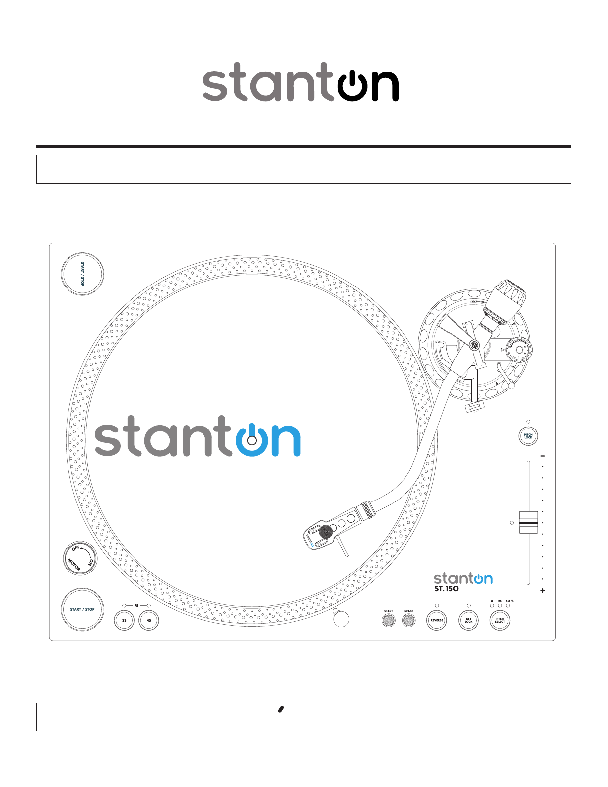
ST.15O DIGITAL TURNTABLE
OWNER S MANUAL
Page 2

Page 3
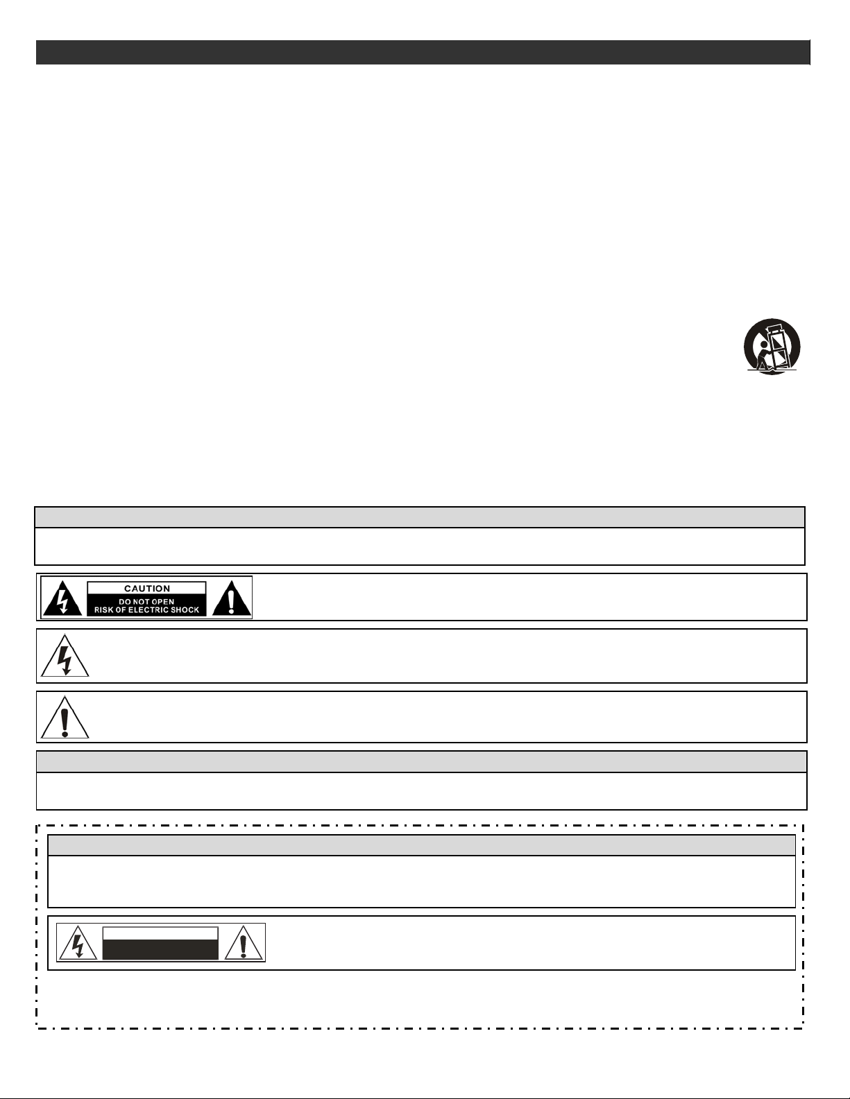
IMPORTANT SAFETY INSTRUCTIONS
A
1
1. Read these instructions.
2. Keep these instructions.
3. Heed all warnings.
4. Follow all instructions.
5. Do not use the apparatus near water.
6. Clean only with dry cloth.
7. Do not block any ventilation openings. Install in accordance with the manufacturer’s instructions.
8. Do not install near any heat sources such as radiators, heat registers, stoves, or other apparatus (including amplifiers) that
produce heat.
9. Do not defeat the safety purpose of the polarized or grounding-type plug. A polarized plug has two blades with one wider than
the other. A grounding- type plug has two blades and a third grounding prong. The wide blade or the third prong is provided for
your safety . If the provided plug does not fit into your outlet, consult an electrician for replacement of the obsolete outlet.
10. Protect the power cord from being walked on or pinched particularly at plugs, convenience receptacles, and the point where they
exit from the apparatus.
11. Only use attachments/ accessories specified by the manufacturer.
12. Use onl y wi th a ca rt, st and , tr ipod, b ra cke t or table specified by the manufacturer, or sold with the appar a tu s.
When a cart is used, use caution when moving the cart/apparatus combination to avoid injury from tip-over.
13. Unplug this apparatus during lighting storms or when unused for long periods of time.
14. Refer all servicing to qualified service personnel. Servicing is required when the apparatus has been damaged in any way,
such as power-supply cord or plug is damaged, liquid has been spilled or objects have fallen into the apparatus, the app arat us
has been exposed to rain or moisture, does not operate normally, or has been dropped.
15. Mains plug is used as disconnect device and it should remain readily operable during intended use. In order to disconnect the
apparatus from the mains completely, the mains plug should be disconnected form the mains socket outlet completely.
16. Caution marking is located at the bottom of apparatus.
17. Please keep the unit in a good ventilation environment.
WARNING
To reduce the risk of fire or electric shock, do not expose this apparatus to rain or moisture. The apparatus shall not be
exposed to dripping or splashing and that no objects filled with liquids, such as vases, shall be placed on the appa ratu s.
CAUTION: To reduce the risk of electric shock, do not remove any cover. No
user-serviceable parts inside. Refer servicing to qualified service personnel only.
The lightning flash with arrowhead symbol within the equilateral triangle is intended to alert the use to the presence
of un-insulated “dangerous voltage” within the product’ s enclosure that may be of suf ficient magnitude to constitute
a risk of electric shock.
The exclamation point within the equilateral triangle is intended to alert the user to the presence of important
operation and maintenance (servicing) instructions in the literature accompanying this applia nce.
CAUTION
To prevent electric shock, do not use this polarized plug with an extension cord, receptacle or other outlet unless the blades
can be fully inserted to prevent blade exposure.
AVERTISSEMENT
vertissement: pour réduire le risque d’incendie ou de choc électrique, ne pas exposer cet appareil sous la pluie et
l’humidité. L'appareil ne doit pas être exposé aux écoulements ou aux éclaboussures et aucun objet ne contenant de
liquide, tel qu'un vase, ne doit être placé sur l'objet.
ATTENTION:Ne démontez pas l’appareil afin de prévenir tout risque de choc électrique.
AVERTISSEMENT
NE PAS O UVRIR
RISQUE DE CHOC ELECTRIQUE
Aucune pièce interne ne peut être réparée par l’utilisateur. Confiez toutes les
opérations d'entretien à un technicien qualifié.
¿ La prise du secteur ne doit pas être obstruée ou doit être facilement accessible pendant son utilisation. Pour être
complètement déconnecté de l'alimentation d'entrée, la prise doit être débranchée du secteur.
¿ Les précautions d'emploi sont inscrites en bas de l'appareil.
Page 4

ASSEMBLY
2
Remove all the parts from the box. Please check to make sure the
following items are included with the main unit in the cart
(1) Platter
(2) Slip
(3) Counterweight
(4) 45-rpm
(5) Stanton Cartridge and Headshell
(6) AC cord
(7) RCA cable
(8) Target light
(9) Operating instructions
mat
adapter
on:
CONNECTIONS
1. Connect the power cord to an AC outlet.
2. Connect the RCA cable to the PHONO input of your mixer. You can
also use a line input by setting the phono/line switch at the rear of the
turntable to Line.
Note: This turntable has separate analog and digital circuits. If you are
looking for a purely analog signal, use the Phono output. For access to
the Key correction feature use the Line output or S/P DIF output.
TONE ARM AND CARTRIDGE SETTINGS
The major cause of problems in sound and skipping on the vinyl is the
lack of proper set up of the needle and turntable adjustments. The needle
is designed to operate at a specific angle to the vinyl. The ST-150 has
several adjustments to correctly position the
The first adjustment is the correct installation of the cartridge.
Your cartridge is to be mounted into t
instructions included with the cartridge. The Stanton 500,680 and 890
series of cartridges require the use of the two screw mounting int
headshell. For your convenience, some of these products can be
purchased already mounted and pre-adj
. If you are using these 1/2” mounted products with a headshell in a
dealer
mobile application or you are doing heavy scratching, you may want to use
an extra shell weight. The Master series of
Groovemaster, etc.) are designed with their own mounting that eliminates
the need f
The body of the cartridge should be parallel with the centerline of the
headshell-tone arm, when viewed from the front to the back.
The second adjustment is at the installation of the
cartridge-head-sh
the tone arm tube in one hand, insert the cartridge-headshell into the tube
lock with the other hand. Turn the lock ring clockwise (when viewed from
the rear) until the headshell is locked tightly into the tone arm. Remove
the needle protector from the cartridge and place the needle on record.
View the needle from the front and insure that the needle is perpendicular
to the record surface. If some adjustment is needed, simply loosen the
lock ring and rotate the cartridge-headshell until the needle is
perpendicular to the record surface. Then re-tighten the lock ring.
The third adjustment is the needle (or stylus) pressure. Start with the
cartridge-headshell assembly mounted into the tone arm. Remove any
needle protectors provided. With tone arm free, adjust the tone arm
counterweight by rotating the rear section until the tone arm floats in a
balanced condition above the record or mat. Do not allow the needle to
drop onto the mat or the turntable platter during this adjustment. You
might damage the needle tip. Now, carefully hold the tone arm in one
hand while rotating the numbered ring on the front of the counter-weight
with the other hand to the “0” setting. Next, without touching the
numbered ring, Rotate the rear counterweight until the desired needle
pressure reading is next to the line on top of the tone arm tube, See the
instructions. Included with your cartridge for proper settings.
The fourth and last adjustment is that of the tone arm height. This
will set the tone arm pivot and needle relation with the vinyl. Unlock the
tone arm base located in the base of pivot assembly
adjust ring in the pivot base to read the correct setting for the height
adjust ring in the pivot base to read the correct setting for the height of
the cartridge that you are using. Check the cartridge/arm height table for
the correct setting. Be certain to re-lock the pivot base when adjustment
is completed.
or a separate headshell and the wiring to the cartridge.
ell assembly into the tone arm tube lock. Holding
needle to the vinyl.
he headshell as pre the mounting
o the
usted from your local Stanton
product
s (T
rackmaster
. Rotate the height
,
Page 5

PART NAMES & FUNCTIONS
3
1
2
3
1
4 65 7 8 9 10
1) START/STOP
Press this button to start or stop the platter.
2) STROBE DOTS
The dots around the edge of the platter are
used in conjunction with the light located inside
the motor ON/OFF switch. While the platter is
in rotation, the dots help to indicate the speed
of rotation. The speed is lower than the
displayed speed (33,45,78) when the dots are
flowing to the right. It is higher than the
displayed speed (33,45,78) when the dots are
flowing to the left. When the strobe is stopped,
the platter is rotating at the displayed speed.
3) MOTOR ON/OFF SWITCH
As opposed to fully analog turntables, this is
not the power switch. This switch only turns on
or off the motor. Rotate clockwise to turn on the
motor. The platter will not start spinning until
the start/stop button has been pressed. Rotate
counter-clockwise during playback (off position)
for a slow winding down effect.
4) PLATTER REVOLUTION SPEEDS (rpm)
33 rpm - Press 33
45 rpm - Press 45
78 rpm - Press 33 and 45 buttons
simultaneously. To return to 33 or 45-rpm play
mode, just press the desired button.
5) TARGET LIGHT
Insert target light to the deck and it will light
up..
1819202122
17
16
15
14
13
12
11
6) START
The Start time is adjustable from 0.2~6 sec.
7) BRAKE
The Brake time is adjustable from 0.2~6 sec.
8) REVERSE
This button is used to reverse the direction of
the platter rotation.
9) KEY LOCK
Press to enable key lock. When key
lock is on, the pitch slider will only affect
the speed of the platter. The key (tone) will
remain at 0%
Note: Key lock processing is only
available when the LINE output is used.
10) PITCH SELECT
Press the button to switch between +/-8%,
+/-25%, or +/-50% pitch range.
11) HEADSHELL LOCKING NUT
Attach the headshell by inserting into the front
end of the tone arm. Turn the locking nut
clockwise with the head shell firmly held
horizontally.
12) PITCH SLIDER
The pitch slider is used to speed up or slow
down the turntable platter.
13) TONE ARM
This is a fully manual tone arm. To start
playback, gently place the stylus on the record
using the headshell finger support. Do not drop
the stylus onto the record as it may cause
damage to the diamond tip and to the record.
14) PITCH ON/OFF
The ON setting will allow use of the pitch adjust.
When set of OFF, the pitch control will be
locked at 0%.
15) TONE ARM BASE
The tone arm base includes the height
adjustment and tone arm rest. See ìtone arm
and cartridge settingsî for proper adjustments.
16) ANTI SKATE KNOB
When a record is playing, a force is generated
drawing the stylus towards the center of the
record. Set this knob to the same value as the
stylus pressure to offset this force.
17) COUNTERWEIGHT
Use this to balance the tone arm and to adjust
the stylus pressure. See ìtone arm and
cartridge settingsî for proper adjustments.
18) LINE OUT L & R
This is the standard analog output (RCA jacks)
which can be connected either to a phono or
line input on any DJ mixer, depending on the
setting of the phono / line selector.
Note: Key lock processing is only
available when the LINE output is used.
19) PHONO/LINE SWITCH
Note: Key lock and Digital output
processing is only available when the LINE
output is used.
20) DIGITAL OUT
Use this output to connect your ST-150 to any
SPDIF in equipped digital device such as a
CD-R or Computer.
21) POWER CORD CONNECTOR
Used to connect the included power cord.
22) POWER SWITCH
This switch turns the power on or off, including
the motor and audio signal.
Page 6

4
SPECIFICATIONS
TURNTABLE SECTION
Starting Torque: More than 4.5kgf.com
Motor: 16pole, 3phase, brushless DC motor
Platter: 332mm dia. Aluminum diecast
Pitch:
Brake:
TONE ARM SECTION
Tone arm type Static balanced S -shaped tonearm
Effective Arm Length 230mm
Tracking Force Adjust Range 0-3g
Applicable Cartridge Weight 13-18g
Frequency Response 20 - 20 KHz
Channel Separation More than 15 dB
Channel Balance Within 2.5dB at 1 KHz
Wow & Flutter: Less than 0.1% WRMS
(JIS WTD) with 33 1/3rpm
S/N ratio: More than 60dB (DIN-B)
Needle Pressure range 2-5g
GENERAL SPECIFICATIONS
Dimensions: 450(W) x 353 (D) x 146 (H)mm
Weight: 16.4Kg
Power supply: Single Voltage:
Power consumption: 14W
+/-8%,+/-25%,+/-50%
Electronic Brake
straight with detachable headshell
AC 100V, 50Hz (For Japan)
AC 110V, 60Hz (For Taiwan)
AC 120V, 60Hz (For U.S.A.,Canada,Mexico)
AC 220V, 50Hz (For United Arab Emirates,Chile,Argentina)
AC 220V, 60Hz (For Philippines)
AC 230V, 50Hz (For Europe,New Zealand,South Africa,Singapore,Israel)
AC 240V, 50Hz (For Australia,U.K.)
Page 7

Ground lift Operation
5
Due to the variety of power sources available to the DJ, Stanton has included a
ground lift switch to be used on the ST- 150/STR8-150 turntables. This will allow
th e DJ to have th e capabilit y of ch
cartridge to avoid ground hum that may
150/STR8-150
and should always be used when available.
G R O U N D F R O M
US E TH E
WH IC H D O
For best operation of the ground lift, the following rules should be applied
W h e n t h ir d p in s a fe ty g ro un d i s u s e d , se t the ground lif t switch to the lift
position. This position will isolate the cartridge ground from connection to
ground.
Wh en t hir d pi n s a fet y gr oun d is u nav a il a bl e, set the ground lift switch to the
connected position.
chassis ground, but since third pin grounding is not used, the
not be in connection with earth.
Turntable has been designed to operate with third pin safety ground,
T HE P O WE R C O RD P R O V ID E D, I F N E C E S SA R Y,
AP PR O PR I AT E A DA PT ER F OR P L UG GI NG I NT O OU TL ET S
NO T P RO VI D E T HI R D P IN GR O UND TE RMI NA LS .
This will place the cartridge ground in connection
an g ing the
occur when using the turntable. The ST-
gr ounding scheme o f the pho no
N E V E R R E M O V E T H I R D P I N
cartridge ground will
earth
with the
Page 8

WARRANTY
6
Thank you for choosing one of Gibson Pro Audio’s brands (Stanton, KRK, or Cerwin Vega!).
Your satisfaction is extremely important to us. We proudly stand behind the quality of our work and appreciate that you put your trust in
us. Registering your merchandise will help us guarantee that you are kept up to date on our latest advances.
To Register Merchandise Purchased from an Authorized Gibson Pro Audio Dealer in the U.S.:
Please go to: http://www.gibson.com and register online.
Or you may send your warranty card to:
Gibson Customer Service
309 Plus Park Blvd.
Nashville, TN 37217
If you have any questions you may contact customer service at:
1-800-4GIBSON (1-800-444-2766)
e-mail: service@gibson.com
FOR MERCHANDISE PURCHASED FROM AN AUTHORIZED GIBSON PRO AUDIO DISTRIBUTOR OUTSIDE OF THE US, PLEASE CONTACT
THE DISTRIBUTOR FROM WHOM YOU PURCHASED YOUR MERCHANDISE FOR TO REGISTER YOUR WARRANTY AND FOR HANDLING AND
RESOLUTION OF ALL WARRANTY-RELATED ISSUES.
Gibson Pro Audio Warranty
If at any time your Gibson Pro Audio product (which includes Stanton, KRK, or Cerwin Vega! brands) malfunctions as a result of faulty
materials or workmanship, Gibson Pro Audio or one of Gibson Pro Audio’s Authorized Service Centers in the US will repair the defect(s) or
replace the merchandise, as it deems appropriate at its sole discretion.
Warranty Period (from date of Purchase as listed on the Bill of Sale):
Stanton
One (1) year for all Stanton products.
KRK
Three (3) years from all studio monitors.
One (1) year all headphones, computer audio devices, including room correction devices.
Cerwin Vega!
Five (5) years for all passive speaker systems.
Three (3) years for all active speaker systems.
One (1) year for mixers.
Page 9

Gibson will warrant all replacement parts and repairs for ninety (90) days from the date of original shipment.
7
In the unlikely event that your merchandise is destroyed, lost or damaged beyond repair while in the possession of Gibson or one of Gibson Pro
Audio’s Authorized Service Centers for repair, Gibson will replace that merchandise with one of the same or most similar style of a value not in
excess of the original purchase price of your merchandise. Any insurance covering the merchandise, including but not limited to collector's value
insurance, must be carried by owner at owner's expense.
For the fastest and safest merchandise return, please use the original shipping carton and packaging materials. Gibson cannot be responsible
for any damages incurred during the shipping process due to poor or inadequate packing.
THIS WARRANTY IS EXTENDED TO THE ORIGINAL RETAIL PURCHASER ONLY AND MAY NOT BE TRANSFERRED OR ASSIGNED TO SUBSEQUENT
OWNERS. IN ORDER TO VALIDATE YOUR WARRANTY, AND AS A CONDITION PRECEDENT TO WARRANTY COVERAGE HEREUNDER, YOU MUST REGISTER
YOUR WARRANTY WITHIN FIFTEEN (15) DAYS FOLLOWING THE ORIGINAL DATE OF PURCHASE.YOUR PROOF OF PURCHASE OR SALES RECEIPT MUST
ACCOMPANY ALL REQUESTS FOR WARRANTY COVERAGE.
This warranty is subject to the following limitations:
THIS WARRANTY DOES NOT COVER
1. Any merchandise that has been altered or modified in any way or upon which the serial number has been tampered with or altered.
2. Any merchandise whose warranty card has been altered or upon which false information has been given.
3. Any merchandise that has been damaged due to misuse, negligence, or improper operation.
4. Any merchandise that has been damaged by accident, flood, fire, lightening, or other acts of God.
5. Shipping damage of any kind.
6. Any merchandise that has been subjected to extremes of humidity or temperature.
7. Any merchandise that has been purchased from an unauthorized dealer, or upon which unauthorized repair or service has been performed.
GIBSON MAKES NO OTHER EXPRESS WARRANTY OF ANY KIND WHATSOEVER. ALL IMPLIED WARRANTIES, INCLUDING WARRANTIES OF
MERCHANTABILITY AND FITNESS FOR A PARTICULAR PURPOSE, EXCEEDING THE SPECIFIC PROVISIONS OF THIS WARRANTY ARE HEREBY
DISCLAIMED AND EXCLUDED FROM THIS WARRANTY. SOME STATES AND/OR COUNTRIES DO NOT ALLOW THE EXCLUSION OR LIMITATION OF
IMPLIED WARRANTIES SO THAT THE ABOVE MAY NOT APPLY TO YOU.
GIBSON SHALL NOT BE LIABLE FOR ANY SPECIAL, INDIRECT CONSEQUENTIAL, INCIDENTAL OR OTHER SIMILAR DAMAGES SUFFERED BY THE
PURCHASER OR ANY THIRD PARTY, INCLUDING WITHOUT LIMITATION, DAMAGES FOR LOSS OF PROFITS OR BUSINESS OR DAMAGES RESULTING
FROM USE OR PERFORMANCE OF THE MERCHANDISE, WHETHER IN CONTRACT OR IN TORT, EVEN IF GIBSON OR ITS AUTHORIZED REPRESENTATIVE
HAS BEEN ADVISED OF THE POSSIBILITY OF SUCH DAMAGES, AND GIBSON SHALL NOT BE LIABLE FOR ANY EXPENSES, CLAIMS, OR SUITS ARISING
OUT OF OR RELATING TO ANY OF THE FOREGOING.
FOR MERCHANDISE PURCHASED FROM AN AUTHORIZED GIBSON PRO AUDIO DISTRIBUTOR OUTSIDE OF THE US, PLEASE CONTACT THE DISTRIBUTOR
FROM WHOM YOU PURCHASED YOUR MERCHANDISE FOR THE HANDLING AND RESOLUTION OF ALL WARRANTY ISSUES. FOR THESE PURCHASES,
THE ABOVE-DESCRIBED WARRANTY IS NOT APPLICABLE.
How to Obtain Warranty Service
Warranty Service outside the United States:
To initiate a warranty repair, please contact the Authorized Gibson Pro Audio distributor from whom you purchased your merchandise, and follow
the distributor’s return/warranty policy.
Warranty Service for Merchandise Purchased from an Authorized Gibson Pro Audio Dealer in the U.S:
In the event of malfunction of your Gibson Pro Audio merchandise, the Dealer or Owner must call Customer Service @ 1-800-4GIBSON (1-800444-2766) and obtain a Return Authorization number from the customer service agent. No merchandise may be returned to Gibson without
such prior Return Authorization, and the Return Authorization number must be written on the outside of the shipping package. The Customer
Service agent will provide the address and additional shipping instructions. Owner must ship the merchandise, freight, and insurance pre-paid
to the address provided by the customer service representative. Only Authorized Gibson Pro Audio Service Centers may perform warranty service
and any service performed by unauthorized persons will void this warranty. Gibson disclaims liability for defects or damage caused by services
performed by unauthorized persons or non-warranty service not performed by Gibson or an Authorized Gibson Pro Audio Service Center.
Page 10

When contacting Gibson, you must include a complete written description of the malfunction of the merchandise. If non-warranty work
8
is required or recommended, a quotation will be issued and must be approved by you before any non-warranty work is commenced. You
should consider quotations obtained for non-warranty work immediately and advise the Authorized Gibson Pro Audio Service Center
or Gibson of your wishes. You are not required to purchase non-warranty work in order to obtain service on materials covered by this
warranty. Following its inspection of merchandise upon its arrival, Gibson or the Authorized Gibson Pro Audio Service Center will advise
you or your dealer of the approximate date of completion. The repaired merchandise or part will be returned to you or your dealer, freight
collect insured.
No representative or other person is authorized to assume for Gibson any liability except as stated in this warranty. This warranty gives
you specific rights which vary from state to state or from country to country.
For further information, write:
Customer Service Dept.,
Gibson Customer Service
309 Plus Park Blvd.
Nashville, TN 37217
Or call:
1-800-4GIBSON
Microsoft® Windows™ is a registered trademark of Microsoft® Corp. Apple® OSX™ is a registered trademark of
Apple® Corp.Virtual DJ™ is a registered trademark of Atomix™ Productions
Page 11

Page 12

http://www.gibson.com
 Loading...