

StantFin Monitron EH, Monitron EH EH8-135S, Monitron EH-40-135S, Monitron EH-12-345S, Monitron H-40-345S Operation And Installation Instructions Manual

MODEL EH ELECTRIC BOILER
EH8-135S through EH-40-135S 3 wire 120/208V, 120/240V single phase
EH-12-345S through EH-40-345S 4 wire 120/208V three phase WYE
OPERATION AND INSTALLATION INSTRUCTIONS
IMPORTANT:
This manual must be left with owner and should be hung
on or adjacent to the boiler for reference.
Publication No. EH-40
HG 10/08-10/08-2m Printed in Canada
Part No. 79-0820
Rev.B
Heating Contractor
Address
Phone Number
Boiler Model Number
Boiler Serial Number
Installation Date
CONTENTS . . . . . . . . . . . . . . . . . . . . . . . . . . . . . . . . . . .PAGE
Description . . . . . . . . . . . . . . . . . . . . . . . . . . . . . . . . . . . . . . . . . 2
Mounting . . . . . . . . . . . . . . . . . . . . . . . . . . . . . . . . . . . . . . . . . . . 2
Piping . . . . . . . . . . . . . . . . . . . . . . . . . . . . . . . . . . . . . . . . . . . . . 2
Air Eliminator and Expansion Tanks . . . . . . . . . . . . . . . . . . 2
Flow Switch . . . . . . . . . . . . . . . . . . . . . . . . . . . . . . . . . . . . . 2
Bypass . . . . . . . . . . . . . . . . . . . . . . . . . . . . . . . . . . . . . . . . . 2
Wiring . . . . . . . . . . . . . . . . . . . . . . . . . . . . . . . . . . . . . . . . . . . . . 2
Wall Thermostat Flow Switch and Circulator . . . . . . . . . . . 2
Service Connections and Electrical Ratings . . . . . . . . . 3–4
Typical Piping . . . . . . . . . . . . . . . . . . . . . . . . . . . . . . . . . . . . . . 5
Typical Zone Valve Wiring . . . . . . . . . . . . . . . . . . . . . . . . . . . . . 6
Start-up . . . . . . . . . . . . . . . . . . . . . . . . . . . . . . . . . . . . . . . . . . . . 7
Fill System . . . . . . . . . . . . . . . . . . . . . . . . . . . . . . . . . . . . . . 7
Air Elimination . . . . . . . . . . . . . . . . . . . . . . . . . . . . . . . . . . . 7
Bypass Flow Adjustment . . . . . . . . . . . . . . . . . . . . . . . . . . 7
Check for Proper Boiler and System Operation . . . . . . . . 7
Operation (models equipped with seq. control system) . . . . . . 7
Periodic Inspection . . . . . . . . . . . . . . . . . . . . . . . . . . . . . . . . . . . 7
Appendix A & B . . . . . . . . . . . . . . . . . . . . . . . . . . . . . . . . . . . . . 8
DESCRIPTION
The Monitron boiler is a low pressure hot water heating electric
boiler. The heating elements are sheathed resistance type. The
heat exchanger is cast-iron. The heat exchanger is constructed,
inspected, and stamped in accordance with Section IV of the
American Society of Mechanical Engineers (ASME) Boiler and
Pressure Vessel Code. In addition, the Monitron Boiler is
equipped with a safety relief valve and an integral dual limit control, conforming to ASME requirements. The Monitron boiler is
CSA listed.
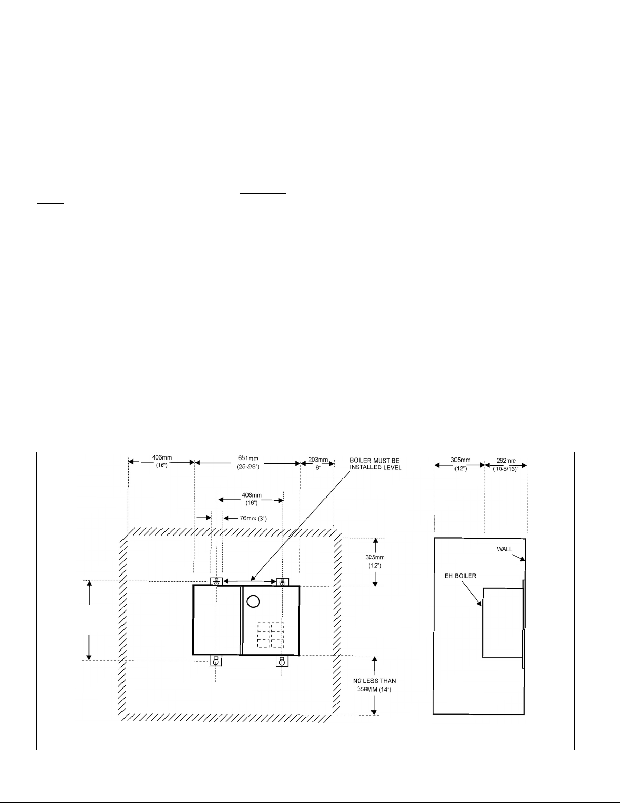
MOUNTING
The Monitron is intended for wall mounting, utilizing the wall
brackets attached to the boiler (see Figure 1). Allow sufficient
space for piping and service. The boiler may be installed in an
enclosed space (see Figure 1). The boiler must be INSTALLED
LEVEL.
PIPING
Air Separator and Expansion Tanks
The recommended piping arrangement is shown in figures 4
through 6. Note that there is a built-in air eliminator in the heat
exchanger (air vent, however, is by others). The air vent tapping is
13mm (1/2”). A bushing (by others) to suit the size of the air vent
thread is required. Additional air vents should be installed at
points just upstream from all drops in elevation of the piping
system (high points).
Relief Valve Discharge Piping
Use same size or larger piping than valve outlet. Must terminate
152mm ( 6”) minimum from floor with a plain ( no threads) end.
Place a bucket under pressure relief valve discharge. Make sure
discharge is always visible. DO NOT hard-pipe to drain piping.
Flow Switch
THE INSTALLATION OF A FLOW SWITCH IS STRONGLY
RECOM MENDED. It is intended to prevent the burnout of heater
elements should the circulator fail, or should air accumulate in
the boiler due to faulty air elimination (see Table 3 for flow switch
size required). FLOW SWITCH MUST BE INSTALLED IN HORIZONTAL POSITION. IF A FLOW SWITCH IS NOT USED JUMPER
THE “FF” TERMINALS (JUMPER NOT SUPPLIED.)
Bypass
The bypass shown must be set so that a sufficient amount of
water can circulate through the boiler when all zone valves are
closed. (See Figure 5 & 6.)
Multi-zone Balancing
Raise all zone thermostat settings and verify that all zone valves
are open (bypass valve should be closed). Close all electrical
panels. Turn on 15 amp control circuit breaker ONLY. Pump
should operate. Note the pressure reading on the pump discharge. Lower each zone thermostat setting to close corresponding zone valve. Adjust the corresponding balancing valve to
maintain pump discharge pressure. The pump discharge pressure should remain the same when all zones are in bypass or
when all zones are open or any combination of opened and
closed. (See Figure 5 & 6.)
WIRING
To wire the electric boiler, perform the following procedures:
1. Wall thermostat, flow switch, outdoor thermostat,
circulator and external transformer
All circuit breakers ahead of and at the boiler must be OFF.
Remove the Control Panel (left-hand front cover) by removing
5 screws from top, bottom and side flanges.
The centre compartment contains a 24V control terminal
board marked, "FF/TT/1-2" (see figure 2 or figure 3.)
Wire a 24V, two-wire heating thermostat or the auxiliary end
switch terminals from zone valves (see Figure 7) to "TT".
The "FF" terminals are for a flow switch.
Do not connect the wires to the flow switch "FF" terminals until
the by-pass flow adjustments are completed. Refer to "Bypass Flow Adjustment" (page 7) for wiring and adjustment
procedures. The flow switch wires should be taped at the boiler until they are to be connected to "FF".
The left compartment contains a 120V terminal board marked
"A-B/Circulator". Wire the circulator and connect wires and
conduit through the 13 mm (1/2") knockout (pro vided on the
bottom left hand corner of the cabinet) to the terminal board
"Circulator" terminals. These terminals supply 120 volts to the
circulator only when there is a call for heat.
2
NOTES:
1. MAY BE TOTALLY ENCLOSED.
2. ALL ABOVE CLEARANCE DIMENSIONS ARE MINIMUM.
3. ALL DIMENSIONS ARE IN METRIC (INCHES).
424mm
(16-11/16”)
475mm
(18-11/16”)
Figure 1. Boiler Mounting
Wire an external zone valve transformer to the "A-B" terminals if zone valves are used. These terminals provide a
constant 120 volts and can alternately be used to power the
circulator if constant circulation is desirable. Use 90°C (75°F)
minimum wire, copper or aluminum.
2. Service Connections and Electrical Ratings
A. All circuit breakers ahead of and at boiler must be OFF.
Remove the Service Connection Panel (right hand front)
cover by removing 5 screws from the top, bottom and
side flanges (see wiring diagram on back of the Service
Connection Panel and Figure 2 & 3).
B. Draw power feeder cable (90°C [75°F]minimum) and
conduit through service K.O. provided on side, top
or bottom.
C. Connect hot lines to main lugs on breaker base (S
models) or to black and red or to black, red and blue
leads (LB models) provided in service compartment. A
ground lead should be drawn and wired to the ground
lug in the service compartment. If rating plate indicates
boiler is a single phase 3-wire or 3-phase 4-wire model,
draw a neutral wire #12 AWG maximum, 90°C (75°F).
minimum and connect to neutral lug or white wire lead
provided in service compartment. See Tables 1 and 2 for
lug sizes and current ratings.
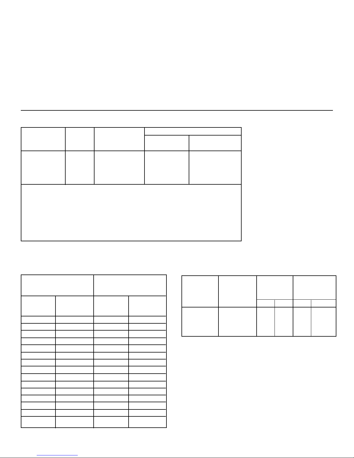
Main * Lug Grounding Lug Wire Size
Wire Size Small Holes Large Holes
Model Phase CU-AL† CU-AL† CU AL†
EH-40 1 2-250 MCM CU DO NOT USE 6-2/0
EH-28 thru 32 1 2-250 MCM DO NOT USE 14-4 6-4
EH-8 thru 24 1 6-2/0 14-8 14-4 6-4
EH-8 thru 40 3 6-2/0 14-8 14-4 6-4
Neutral Lug Wire Size: For 3-wire single phase and 4-wire 3 phase models
equipped with circuit breakers
Small Holes accommodate: #14-12 Solid CU or AL † and #12 stranded CU or AL†
Large Holes accommodate: #14-8 Solid CU, #10-4 Stranded CU and #6-4 AL †
The maximum wire size of the neutral should not exceed 12 AWG in order for 51 mm (2”)
conduit to accommodate incoming power feeder, plus the neutral wire and a ground conductor for the larger models.
Table 1. Lug Sizes
* For models with circuit breakers only.
† ALUMINUM conductors may be used, lug size, conduit size, ampacity and all applicable
codes permitting. However, aluminum conductors may NOT be used for model EH-40 single phase.
SINGLE PHASE 3 WIRE THREE PHASE, 4 WIRE
120/208V, 120/240V‡ 120/208V-WYE
CIRCUIT ONLY‡
Basic Heater Basic Heater
Model Amperes* Model Amperes†
No. @240V No. @208V
EH-8 33
EH-9 38
EH-10 42
EH-12 50 EH-12 25
EH-15 63
EH-16 67 EH-16 38†
EH-18 75
EH-20 83 EH-20 48†
EH-24 100 EH-24 60†
EH-25 104
EH-28 117 EH-28 60†
EH-30 125
EH-32 133 EH-32 73†
EH-35 146
EH-40 167 EH-40 95†
Table 2. Current Ratings
* For current values @ 208V, multiply current @ 240V by 0.867.
† Leg with the highest value of line current of an unbalanced 3-phase load.
‡ 125 VAC maximum rating of all hot conductors.
Flow Switch Minimum
Model McDonnell Pipe Length of
No. & Miller No. Size Straight Pipe*
mm in. mm in.
EH-40 FS8V 32 1-1/4 216 8-1/2
EH-8 thru
EH-35 FS4-3T3-1 25 1 165 6-1/2
Table 3. Flow Switch Size Selection
* Both upstream and downstream of flow switch
3

4
Figure 2: Typical Wiring Diagram for Models equipped with Circuit Breakers
Figure 3: Typical Wiring Diagram for Models without Circuit Breakers
FOR OUTDOOR THERMOSTAT OR
OTHER CONTROL TO MODULATE
BOILER IN MILDER WEATHER
For three phase,
third power leader
lug is added.
TO ZONE VALVE TRANSFORMER
OR FOR CONSTANT CIRCULATOR
OPERATION WHEN DESIRED
For three phase, neutral lug is
used for third power feeder lug
and a separate neutral lug is
added.
TYPICAL WIRING DIAGRAM
TYPICAL WIRING DIAGRAM
TO ZONE VALVE TRANSFORMER
OR FOR CONSTANT CIRCULATOR
OPERATION WHEN DESIRED
FOR OUTDOOR THERMOSTAT OR
OTHER CONTROL TO MODULATE
BOILER IN MILDER WEATHER
HOT
NEUTRAL
HOT

32mm (1-1/4") SUPPLY TAPPING
32mm (1-1/4")
RETURN
TAPPING
NOTES:
1. Optional blocking gate valve and hose end valve used (with drain valve) for fast fill and purge of system.
IMPORTANT: Close bypass line valve (if used) during purging.
2. Circulator should not be installed at lowest point of piping.
3. There should be no elbows, tees, or change of pipe size for at least 5 diameters of pipe size (see Table 3) upstream and downstream of flow switch.
Flow switch should always be mounted in the horizontal position. See Table 3.
32mm (1-1/4") SUPPLY TAPPING
32mm (1-1/4")
RETURN
TAPPING
32mm (1-1/4") SUPPLY TAPPING
32mm (1-1/4")
RETURN
TAPPING
5
Figure 4. Typical Single Zone Piping
Figure 5. Typical Multi-Zone Using 2-Way Valves
Figure 6. Typical Multi-Zone Using 3-Way Valves
THROTTLING
VALVE
ALTITUDE,
PRESSURE,
TEMPERATURE
GAUGE
PRESSURE,
PRESSURE,

Figure 7. Typical Zone Valve Wiring
Figure 7a. Multizoning of boiler; pump zoning system using R845A relay.
6
LOW
VOLTAGE
(24V)
TERMINAL
BLOCK
LINE VOLTAGE (120V)
TERMINAL BLOCK
FOR OUTDOOR
THERMOSTAT IF
USED OR
JUMPERED IF NOT.
2
1
MULTIZONING OF BOILER;
PUMP ZONING SYSTEM USING R845A RELAY
T T
BOILER
A
B

START-UP
NOTE: Make sure that all circuit breakers ahead of and at the
boiler are OFF.
Fill System
See Figures 4 through 6 for suggested purge valve and blocking valve. If system is filled but not purged, radiators must be
vented individually, to prevent air blocking of water flow. Fill
approximately 83 kPa (12 psi) (cold water), whether automatic
or manual fill is used. Do not apply full line pressure to system;
boiler and relief valve are rated at 207 or 345 kPa (30 or 50 psi)
(see rating plate). Suddenly applied main pressure can exceed
690 kPa (100 psi).
WATER CONTENT OF BOILER
All models EH-8 through EH-40 14.2 litres (3.75 U.S. Gallons)
Air Elimination
Diaphragm tank and air vent valve are recommended, see
Figures 4 through 6. Air remaining in system will vent from the
automatic vent valve during system operation. Valve cap must
be loose or removed to allow automatic venting. Open relief
valve briefly after filling to pressure, to make sure boiler is free
of air.
Bypass flow adjustment (Figure 5 & 6)
Close bypass valve. Turn down all zone thermostats. Inspect
all zone valves to be sure all are closed. Put a jumper on TT
terminals. Close ALL panels and turn on the 15 AMP control
circuit breaker ONLY. Be certain that the flow switch wires are
not connected to the flow switch terminals and the ends of
the wires are taped. Connect the ohmmeter or other continuity tester across the common terminal and the terminal that is
normally open during NO FLOW. Slowly open bypass valve
until continuity tester lights or ohmmeter kicks to zero: flow
switch now has closed contacts, indicating required minimum bypass flow rate when piping circuits are shut off.
Bypass valve should be locked at this position. Shut OFF
ALL circuit breakers ahead of and at boiler and open CONTROL PANEL (left hand FRONT COVER). Remove jumper on
“TT” terminals. Connect zone valve end switches (in parallel)
to thermostat “TT” terminals. See figure 7 and wiring diagram
on boiler. Connect flow switch wire to flow switch common
and N.O. terminals and to the “FF” terminals in the boiler.
Replace CONTROL PANEL COVER.
Check for Proper Boiler and System Operation
To check for proper boiler and system operation, perform the
following procedures:
1. Turn up all room thermostats.
2. There will be a delay of up to five minutes before all circuits
are energized.
3. Current may be checked by a qualified electrician at the
feeder panel and compared to the values shown in Table 2.
4. Water flow through the boiler should be sufficient to keep
the flow switch closed. The limit thermostat should also
remain closed. The LOW LIMIT of the dual limit aquastat is
factory set at a normal temperature of 180°F or 82°C; it may
be increased for the purpose of check-out if the load is very
low. The aquastat is located on the left end of the boiler
behind a round cover plate. Loosen screw and rotate cover
to view aquastat.
OPERATION
(Models equipped with Sequential Control System)
These models contain a "S" in the model number which is
located on the rating plate on the top surface of the boiler.
IMPORTANT:
DO NOT operate boiler until the following criteria have
been met:
1. Must be installed by qualified heating and electrical
contractors in accordance with instructions in this
manual.
2. Must be installed in compliance with local codes.
3. Must be inspected and approved by installing contractors and any local authority having jurisdiction, and be
approved for operation by them.
• Ask the installer to explain operation of the entire heating
system.
• Turn on all circuit breakers for boiler and circulator.
• Adjust wall thermostat to required temperature. If room
temperature is lower than the thermostat setting, the
first heater stage will go on immediately and the balance
of the heater stages will go on one at a time with a
delay of between several seconds and 1-1/2 minutes
between stages.
• In mild weather you may wish to reduce the total output of
heat. You may do this by turning off one or more of the
circuit breakers on the boiler. Do not turn off the 15 AMP
control circuit breaker.
IMPORTANT
You must turn on the circuit breaker marked "15" in order to
operate the boiler control system. You then may turn on any
one or more of the other circuit breakers (those marked 25,
30, 35, 50, or 60), depending on the amount of heat required.
PERIODIC INSPECTION
The hot water system, which includes the Monitron boiler, the
radiators and water control devices, should remain filled with
water at all times. DO NOT drain except to make repairs or to
prevent freeze-up during extended cold weather shutdown.
The pressure/temperature gauge on the Monitron should be
checked frequently: at the highest operating temperature,
pressure should be the same throughout the heating season.
If pressure (at a constant temperature) consistently rises or
falls over a period of time, a fill valve leak, a system leak or
compression tank malfunction is indicated. Leaks anywhere
in the system must be repaired without delay. Regular addition of fresh water to replenish leaks adds oxygen and lime.
Oxygen corrosion will cause further leaks and parts failure,
lime buildup on heating elements will cause element failure
due to overheating. If any leaks are found, or if pressure
changes, call for service immediately.
IMPORTANT
Under no circumstances should any electrical wiring or
internal controls be touched, except by an authorized
electrician (wiring and controls) or heating system service
expert (system service, repair, shutdown). Any mechanical adjustments to the heating equipment and system
must be made by a qualified heating serviceperson.
7

Appendix A
Thermostat Heat Anticipator Settings
Fixed anticipator thermostats are not adjustable. Adjustable anticipator thermostats, depending on thermostat
model, may be adjustable from a . 18 to a .9 setting by moving a pointer on the anticipator.
The higher the anticipator setting (towards .9) the longer it will take for the thermostat to respond to a change in
room temperature. Too high a setting and the boiler will be slow to respond to a temperature change in the room.
This can cause the room temperature to drop to an uncomfortable level before the boiler starts. This may generate
homeowner complaints.
The lower the anticipator setting (toward .18) the faster the thermostat will respond to a change in room temperature.
Too low a setting and the boiler will short cycle. Boiler short cycling will cause unnecessary wear on the equipment
and in the case of oil boilers it can lead to poor combustion and more frequent cleaning of the combustion area.
It is important to understand what the thermostat is controlling and then determine the amp rating of that relay, gas
valve, zone valve or control. This information is usually stamped somewhere on the component. A properly set anticipator will allow the system to operate at its maximum effectiveness
Appendix B
Accumulation of foreign deposits in heat exchanger
Recent investigations of boilers which were installed in hard water areas, revealed that mineral deposits had accumulated in the heat exchanger. In addition, sludge, scale and other solid contaminants were present in boilers installed
in older systems or where the water was supplied from a well. This accumulation creates an insulating layer that
drastically may affect boiler efficiency.
THE TERMS OF THE BOILER WARRANTY WILL NOT APPLY TO FAILURES ENCOUNTERED UNDER THESE
CIRCUMSTANCES.
RECOMMENDATIONS:
On all installations in hard water areas:
1. The system should be thoroughly inspected for leaks which must be repaired
however minor they may be.
2. The initial water charge of the system must be treated to reduce its hardness
to an acceptable level.
In addition to the aforementioned, older systems and those supplied from wells may require that a filter or strainer be
incorporated in the circuit at some point on the return line closest to the boiler. Suitable water treatment filters are
commercially available for this purpose.
WE STRONGLY RECOMMEND THAT YOU CONVEY THIS VITAL INFORMATION TO ALL PARTIES CONCERNED.
Water Treatment
A good water treatment program will not only extend the useful life of this boiler but it will also save much of the time
and expense of repairs made necessary by preventable occurrences. A reputable water treatment company should
be consulted to evaluate and determine the best overall treatment program for your boiler equipment.
Appendix C
Replacement of Electric Heaters and gaskets
When replacing electric heaters replace the gasket at the same time. It is not recommended to re-use an old gasket
as it may have become damaged or brittle. To prevent binding and leaks when installing a new gasket wet the
gasket with water or coat it with talcum powder to allow it to move into position properly without binding.
SLANT/FIN LTD/LTEE, 6450 Northam Drive, Mississauga, On L4V 1H9
Phone: (905) 677-8400 / FAX: (905) 677-1829
Order Deak: (905) 677-9319
www.slantfin.ca / E-mail: orderdesk@slantfin.ca info@slantfin.ca
 Loading...