

Page 1
www.stanley.eu
FME721
Page 2
2
1
2
3
5
7
6
4
8
9
10
11
12
13
14
25
15
16
17
18
19
20
21
22
23
24
A
www.stanley.eu
FME721
Page 3
3
7
26
27
15
15
28
29
23
18
9
30
1 2
3 4
5
6
Page 4
4
23
31
32 21
22
33
10
10
36
34
35
6
37
7 8
9 10
11 12
Page 5
5
25
39
29
40
41
30
42
38
43
3044
14
545
13 14
15 16
17
46 18
18
Page 6
6
9
49
49
50
17
48
9
51
12
19
13
6
19
21
22 23
24 25
20
A
24a
Page 7
7
1
6
17
52
32
33
21
10
52
17
26 27
28
29 30
Page 8
8
9 21
9
53
54
33 32
10
54
36
53
30
18
35
3455
31 32
33 34
35 36
Page 9

9
36
55
34
56
58
57
37 38
39
40
30
18
53
Page 10

10
ENGLISH
(Original instructions)
Intended use
Your Stanley Fat Max FME721 sliding compound mitre saw has
been designed for sawing wood, plastic and nonferrous metal
only. This tool is intended for professional and private, non
professional users.
Safety instructions
General power tool safety warnings
@
Warning! Read all safety warnings and all
instructions. Failure to follow the warnings and
instructions listed below may result in electric
shock, re and/or serious injury.
Save all warnings and instructions for future reference.
The term "power tool" in all of the warnings listed below refers
to your mains operated (corded) power tool or battery operated (cordless) power tool.
1. Work area safety
a. Keep work area clean and well lit. Cluttered or dark
areas invite accidents.
b. Do not operate power tools in explosive atmospheres,
such as in the presence of ammable liquids, gases
or dust. Power tools create sparks which may ignite the
dust or fumes.
c. Keep children and bystanders away while operating a
power tool. Distractions can cause you to lose control.
2. Electrical safety
a. Power tool plugs must match the outlet. Never modify
the plug in any way. Do not use any adapter plugs
with earthed (grounded) power tools. Unmodied plugs
and matching outlets will reduce risk of electric shock.
b. Avoid body contact with earthed or grounded
surfaces such as pipes, radiators, ranges and
refrigerators. There is an increased risk of electric shock
if your body is earthed or grounded.
c. Do not expose power tools to rain or wet conditions.
Water entering a power tool will increase the risk of
electric shock.
d. Do not abuse the cord. Never use the cord for
carrying, pulling or unplugging the power tool. Keep
cord away from heat, oil, sharp edges or moving
parts. Damaged or entangled cords increase the risk of
electric shock.
e. When operating a power tool outdoors, use an
extension cord suitable for outdoor use. Use of a cord
suitable for outdoor use reduces the risk of electric shock.
f. If operating a power tool in a damp location is
unavoidable, use a residual current device (RCD)
protected supply.
Use of an RCD reduces the risk of electric shock.
3. Personal safety
a. Stay alert, watch what you are doing and use common
sense when operating a power tool. Do not use a
power tool while you are tired or under the inuence
of drugs, alcohol or medication. A moment of inattention
while operating power tools may result in serious personal
injury.
b. Use personal protective equipment. Always wear eye
protection. Protective equipment such as dust mask,
non-skid safety shoes, hard hat, or hearing protection
used for appropriate conditions will reduce personal
injuries.
c. Prevent unintentional starting. Ensure the switch is in
the off-position before connecting to power source
and/or battery pack, picking up or carrying the tool.
Carrying power tools with your nger on the switch or
energising power tools that have the switch on invites
accidents.
d. Remove any adjusting key or wrench before turning
the power tool on. A wrench or a key left attached to a
rotating part of the power tool may result in personal injury.
e. Do not overreach. Keep proper footing and balance at
all times. This enables better control of the power tool in
unexpected situations.
f. Dress properly. Do not wear loose clothing or
jewellery. Keep your hair, clothing and gloves away
from moving parts. Loose clothes, jewellery or long hair
can be caught in moving parts.
g. If devices are provided for the connection of dust
extraction and collection facilities, ensure these are
connected and properly used. Use of dust collection can
reduce dust-related hazards.
4. Power tool use and care
a. Do not force the power tool. Use the correct power
tool for your application. The correct power tool will do
the job better and safer at the rate for which it was
designed.
b. Do not use the power tool if the switch does not turn it
on and off. Any power tool that cannot be controlled with
the switch is dangerous and must be repaired.
c. Disconnect the plug from the power source and/or the
battery pack from the power tool before making any
adjustments, changing accessories, or storing power
tools. Such preventive safety measures reduce the risk of
starting the power tool accidentally.
d. Store idle power tools out of the reach of children and
do not allow persons unfamiliar with the power tool or
these instructions to operate the power tool. Power
tools are dangerous in the hands of untrained users.
Page 11

11
ENGLISH
(Original instructions)
e. Maintain power tools. Check for misalignment or
binding of moving parts, breakage of parts and any
other condition that may affect the power tools
operation. If damaged, have the power tool repaired
before use. Many accidents are caused by poorly
maintained power tools.
f. Keep cutting tools sharp and clean. Properly
maintained cutting tools with sharp cutting edges are less
likely to bind and are easier to control.
g. Use the power tool, accessories and tool bits etc. in
accordance with these instructions, taking into
account the working conditions and the work to be
performed. Use of the power tool for operations different
from those intended could result in a hazardous situation.
5. Service
a. Have your power tool serviced by a qualied repair
person using only identical replacement parts. This will
ensure that the safety of the power tool is maintained.
Additional power tool safety warnings
@
Warning! Additional safety warnings for mitre
saws.
u Do not use cracked/bent/damaged/deformed saw blades.
u Replace the table insert when worn.
u Do not use blades of larger or smaller diameter than
recommended. For the proper blade rating refer to the
technical data. Use only the blades specied in this
manual, complying with EN 847-1.
u Do not use High Speed Steel (HSS) saw blades.
u Wear gloves when handling saw blades and rough
material (saw blades should be carried in a holder when
practicable).
u Use the dust bag provided when sawing wood.
u Hold power tool by insulated gripping surfaces when
performing an operation where the cutting accessory
may contact hidden wiring or its own cord. Cutting ac-
cessory contacting a "live" wire may make exposed metal
parts of the power tool "live" and could give the operator
an electric shock
u Use clamps or another practical way to secure and
support the work piece to a stable platform. Holding
the work by hand or against your body leaves it unstable
and may lead to loss of control.
@
Warning! Contact with or inhalation of dusts
arising from sawing applications may endanger
the health of the operator and possible bystand-
ers. Wear a dust mask specically designed for
protection against dust and fumes and ensure
that persons within or entering the work area are
also protected.
u Consider using specially designed noise-reduction blades.
u Select the correct blade for the material to be cut.
u This mitre saw has been designed for sawing wood,
plastic and nonferrous metal only.
u Do not operate the machine without the guard in position.
Do not operate the machine if the guard does not function
or is not maintained properly.
u Ensure that the arm is securely xed when performing
bevel cuts.
u Before each cut ensure that the machine is stable.
u Keep handles dry, clean and free from oil and grease.
u Keep the surrounding area of the machine well maintained
and free of loose materials, e.g. chips and off-cuts.
u Ensure the machine and the work area are provided with
adequate general or localised lighting.
u Do not allow untrained people to operate this machine.
u Ensure that the blade is mounted correctly before use.
Make sure that the blade rotates in the correct direction.
Keep the blade sharp. Follow instruction for lubricating
and changing accessories.
u Ensure the speed marked on the saw blade is at least
equal to the speed marked on the saw;
u The laser tted must never be exchanged with a different
type of laser. Repairs to the laser should be carried out by
authorised repair agents or Stanley Fat Max service staff.
u Disconnect the machine form the mains before carrying
out any maintenance or when changing the blade.
u Never perform any cleaning, maintenance, removal of any
off-cuts or other parts of the work piece form the cutting
area when the machine is running and the saw head is not
in the rest position.
u When possible, always mount the machine to a bench.
u Secure the work piece. A work piece held with a clamping
device or a vice is more secure than when held with the
hand.
u Always rmly clamp the piece to be worked to the saw
table. Do not work with pieces that are too small to clamp,
otherwise, the distance of the hands to the rotating saw
blade is too small. Always use extra support when sawing
long work pieces.
u Make sure all locking knobs and handles are tight before
starting any operation.
u Never use your saw without the table insert.
u Never place either hand in the blade area when the saw is
connected to the mains supply.
u Never attempt to stop the machine in motion rapidly by
jamming a tool or other means against the blade; serious
accidents can be caused unintentionally in this way.
u Before using or tting any accessory consult the instruc-
tion manual. The improper use of an accessory can cause
damage.
u Do not use any abrasive discs.
Page 12

12
ENGLISH
(Original instructions)
u Raise the blade from the table insert in the work piece
prior to releasing the on/of switch.
u Do not wedge anything against the fan to hold the motor
shaft.
u The blade guard on your saw will automatically raise when
the arm is brought down; it will lower over the blade when
the arm is raised. The guard can be raised by hand when
installing or removing saw blades or for inspection of the
saw. Never raise the blade guard manually unless the
machine is switched off.
u Check periodically that the motor air slots are clean and
free of chips.
u Do not work with material containing asbestos. Asbestos
is considered to be carcinogenic.
u Never make the warning signs on the power tool unrecog-
nizable.
u Never stand on the power tool. Serious injuries could
occur when the power tool tips over or when coming in
contact with the saw blade.
u Do not take hold of the saw blade after working before it
has cooled. The saw blade becomes very hot while working.
u Advance the saw blade against the work piece only when
it is switched on. Otherwise, the danger of kick-back exists
when the saw blade catches in the work piece.
u The intended use is described in this instruction manual.
The use of any accessory or attachment or performance
of any operation with this tool other than those recommended in this instruction manual may present a risk of
personal injury and/or damage to property.
u Never place hands near cutting area. Keep hands outside
the “No Hands Zone” which includes entire table and is
labelled by “No Hands” symbols.
u To avoid injury from materials being thrown, unplug the
saw to avoid accidental starting, and then remove small
materials.
u Before use and after any maintenance the blade guard
must be checked to ensure proper function. This test must
be performed with the saw switched off and unplugged.
The arm must be raised and lowered to ensure the
guard covers the blade and the blade does not contact
the guard. If the guard fails to operate correctly, have
your power tool serviced by a qualied repair agent.
Call Stanley Fat Max customer services for you nearest
service agent.
Residual risks.
The following risks are inherent to the use of saws:
Even with the application of the relevant safety regulations
and the implementation of safety devices, certain residual
risks can not be avoided. These include:
u Injuries caused by touching any rotating/moving parts.
u Impairment of hearing.
u Risk of accidents caused by the uncovered parts of the
rotating saw blade.
u Risk of injury when changing any parts, blades or acces-
sories.
u Risk of squeezing ngers when opening the guards.
u Health hazards caused by breathing dust developed when
sawing wood, especially oak, beech and MDF.
u Injuries caused by prolonged use of a tool. When using
any tool for prolonged periods ensure you take regular
breaks.
Additional safety instructions for lasers
This laser complies with class ll according to IEC 608251:2007. Do not replace a laser diode with a different type. If
the laser is damaged, have the laser repaired by an authorised repair agent. Do not use the laser for any purpose other
than projecting laser lines.
u Never look into the laser beam directly and intentionally.
u Do not use optical tools to view the laser beam.
u Do not set up the tool where the laser beam can cross any
person at head height.
u Do not let children come near the laser.
Warning! Avoid direct eye contact. Laser radiated when laser
guide is turned on. Avoid direct eye contact. Always unplug the
mitre saw from power source before making any adjustment.
u A laser pointer is not a toy and should not come into
hands of children. Misuse of this appliance can lead to
irreparable eye injuries.
u Any adjustment to increase the laser power is forbidden.
Any liability for damages as a result of not following these
safety instructions will be rejected.
u When using the laser pointer, do not point the laser beam
towards people and/or reecting surfaces. Even a laser
beam of lower intensity may cause eye damage. Therefore, do not look directly into the laser beam.
u The laser pointer includes no servicing components. Do
not open the housing otherwise the guarantee is void.
Safety of others
u This saw is not intended for use by persons (including
children) with reduced physical, sensory or mental capabilities, or lack of experience and knowledge, unless they
have been given supervision or instruction concerning use
of the appliance by a person responsible for their safety.
u Children should be supermaterial clampd to ensure that
they do not play with the appliance.
Vibration
The declared vibration emission values stated in the technical
data and the declaration of conformity have been measured
in accordance with a standard test method provided by
EN 60745 and may be used for comparing one tool with
another.
Page 13

13
ENGLISH
(Original instructions)
The declared vibration emission value may also be used in a
preliminary assessment of exposure.
Warning! The vibration emission value during actual use of
the power tool can differ from the declared value depending
on the ways in which the tool is used. The vibration level may
increase above the level stated.
When assessing vibration exposure to determine safety
measures required by 2002/44/EC to protect persons regularly
using power tools in employment, an estimation of vibration
exposure should consider, the actual conditions of use and the
way the tool is used, including taking account of all parts of the
operating cycle such as the times when the tool is switched off
and when it is running idle in addition to the trigger time.
Labels on tool
The following pictograms along with the date code are shown
on the tool:
:
Warning! To reduce the risk of injury, the user
must read the instruction manual.
O
Wear safety glasses or goggles
N
Wear ear protection
6
Wear a dust mask.
This product is not to be used by children
under 16.
No Hands Zone - Keep ngers and arms away
from rotational saw blades.
Wear gloves when handling saw blades.
Warning! Laser radiation.
Do not look into the laser beam.
Do not view the laser beam directly with optical
instruments.
LASER LIGHT. LASER RADIATION
DO NOT STARE INTO BEAM.
CLASS 2 LASER PRODUCT.
Wavelength: 650nm Power: <1mW
EN 60825-1 :2007
Electrical safety
#
This tool is double insulated; therefore no earth wire
is required. Always check that the power supply corresponds to the voltage on the rating plate.
Inspect tool cords periodically. If the supply cord is damaged,
it must be replaced by the manufacturer or an authorised
Stanley Fat Max Service Centre in order to avoid a hazard.
Voltage drops
Inrush currents cause short-time voltage drops. Under unfavourable power supply conditions, other equipment may be
affected. If the system impedance of the power supply is lower
than 0.34 Ω, disturbances are unlikely to occur.
Using an extension cable
Always use an approved extension cable suitable for the
power input of this tool (see technical data). Before use,
inspect the extension cable for signs of damage, wear and
ageing. Replace the extension cable if damaged or defective.
When using a cable reel, always unwind the cable completely.
Use of an extension cable not suitable for the power input of
the tool or which is damaged or defective may result in a risk
of re and electric shock.
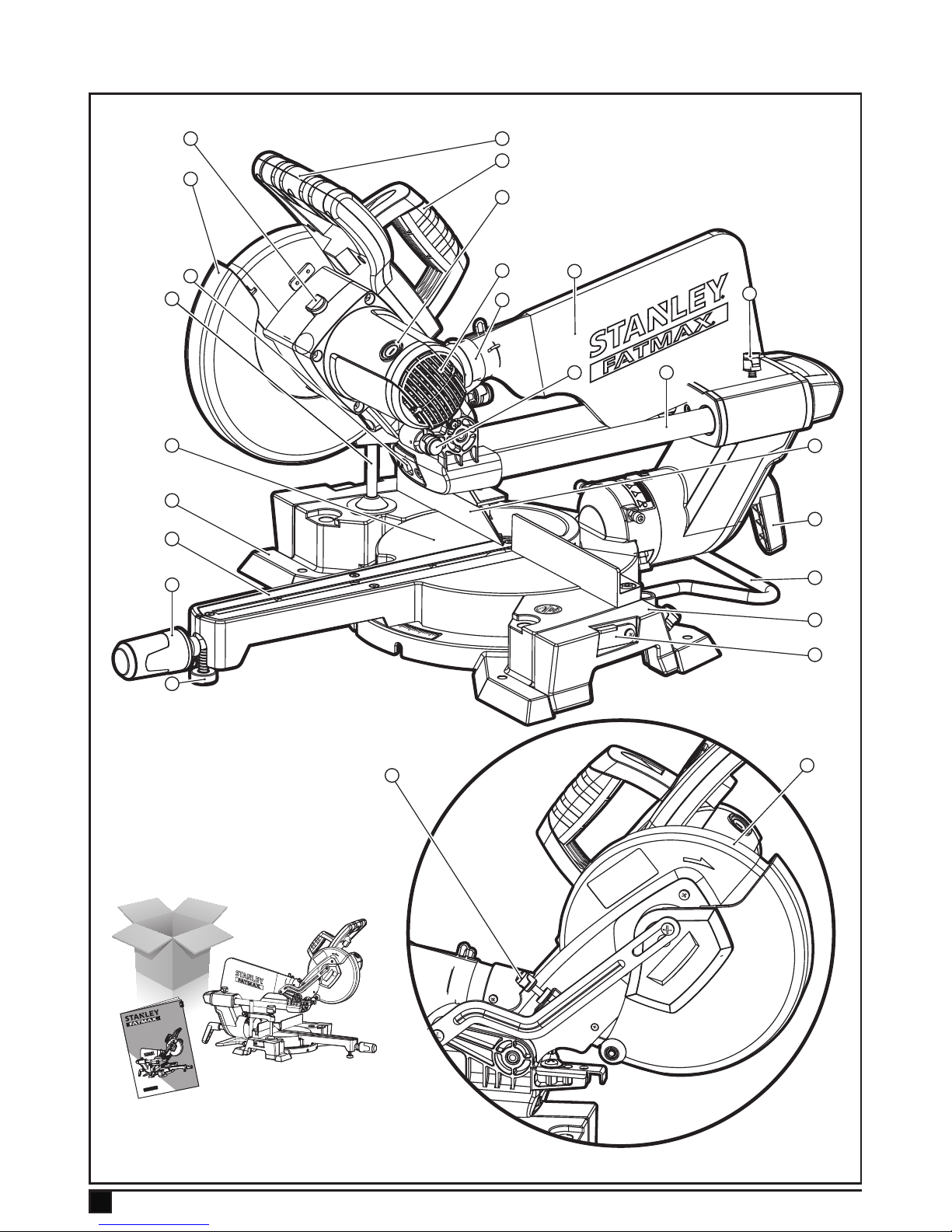
Features
This tool includes some or all of the following features.
1. Handle
2. Carrying handle
3. Carbon brushes
4. Motor
5. Dust bag
6. Track arm lock knob
7. Stopper pin
8. Track arm guide bars
9. Fence
10. Saw head tilt lock lever
11. Back supporting bracket
12. Side extension table
13. Stock stop
14. Dust extraction adapter
15. Retractable guard
16. Laser
17. Material clamp
18. Turn table
19. Base
20. Table insert
21. Grip for rotating table
22. Height adjustment foot
23. Cutting depth limiter
24. Saw head
25. Shaft lock
Page 14

14
ENGLISH
(Original instructions)
Assembly
Warning! Before assembly, make sure that the tool is
switched off and unplugged.
Note: This tool is accurately adjusted before shipping from
the factory. Check the following accuracy and readjust them if
necessary in order to obtain the best results in operation
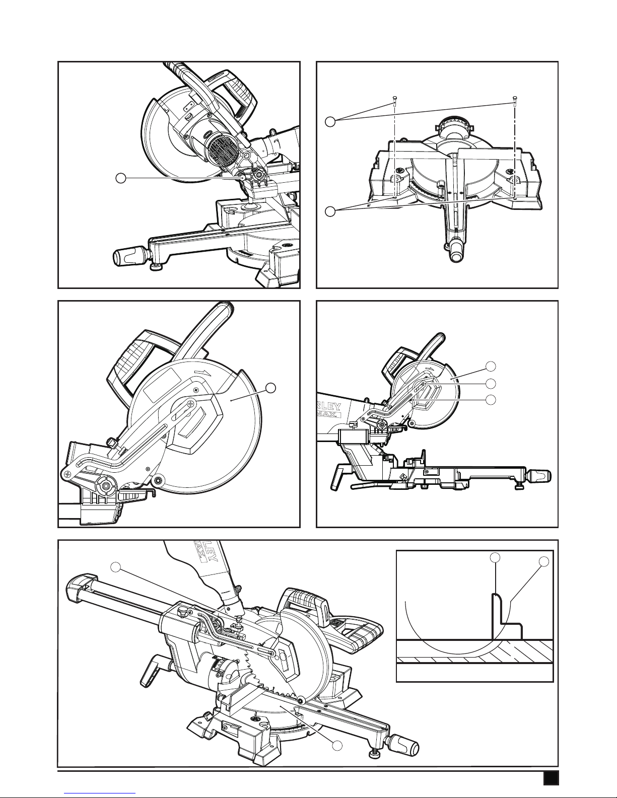
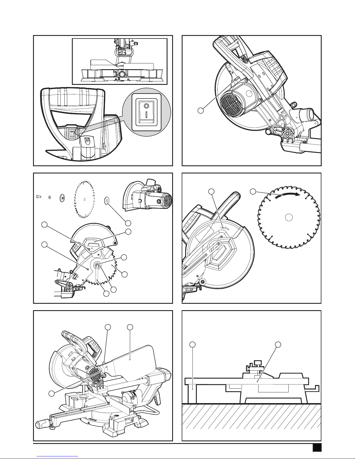
Bench mounting (Fig.1, Fig.2)
When the tool is shipped, the handle is locked in the lowered
position by the stopper pin (7). Pull the stopper pin (7) and
rotate it 90º, either clockwise or counterclockwise.
Alternatively, the tool can be bolted with four bolts (26) (not
provided) to a level and stable surface using the bolt holes
(27) provided in the tools base. This will help prevent tipping
and possible injury.
Warning! Always be sure that the tool is switched off and
unplugged before adjusting or checking the tools function.
Retractable blade guard (Fig.3, Fig.4)
When lowering the handle, the Retractable blade guard (15)
rises automatically. the blade guard (15) returns to its original
position when the cut is completed and the handle is raised.
Warning! Never alter or remove the blade guard or the spring
attached to the guard.
Warning! For your personal safety, always maintain the blade
guard in good condition. Any irregularities in the blade guard
should be corrected immediately. Check the spring loaded return action of the guard. Never use the tool if the blade guard
or spring is damaged, faulty or removed. Doing so is highly
dangerous and can cause serious personal injury.
If the transparent blade guard (15) becomes dirty, or sawdust
adheres to it in such a way that the blade and/or work piece
are no longer visible, unplug the saw and clean the guard
carefully with a damp cloth.
Warning! Do not use solvents or any petroleum based cleaners on the plastic guard.
If the blade guard (15) is especially dirty and vision through
the guard is impaired, use a star-head screwdriver to loosen
the screw (28) holding the centre cover. Loosen the screw (29)
by turning it counterclockwise and raise the blade guard and
Centre cover.
With the blade guard so positioned, cleaning can be more
completely and efciently accomplished. When cleaning is
complete, reverse procedure above and secure bolt. Do not
remove spring holding blade guard. If guard becomes discoloured through age or UV light exposure, contact a service
centre for a new guard. Do not alter or remove guard.
Maintaining maximum cutting capacity (Fig.5, Fig.6)
Unplug the tool before any adjustment is attempted. This tool
is factory adjusted to provide the maximum cutting capacity for
a 216mm saw blade.
When installing a new blade, always check the lower limit
position of the blade and if necessary, adjust it as follows:
u Unplug the tool.
u Push the carriage toward the guide fence (9) fully and
lower the handle completely.
u Adjust the cutting depth limiter (23) until the periphery of
blade (30) extends slightly below the top surface of the
turn table (18).
u With the tool unplugged, rotate the blade by hand while
holding the handle all the way down to be sure that the
blade does not contact any part of the lower base.
u Re-adjust slightly if necessary.
Caution! After installing a new blade, always be sure that
the blade does not contact any part of the lower base when
the handle is lowered completely. Always do this with the tool
unplugged.
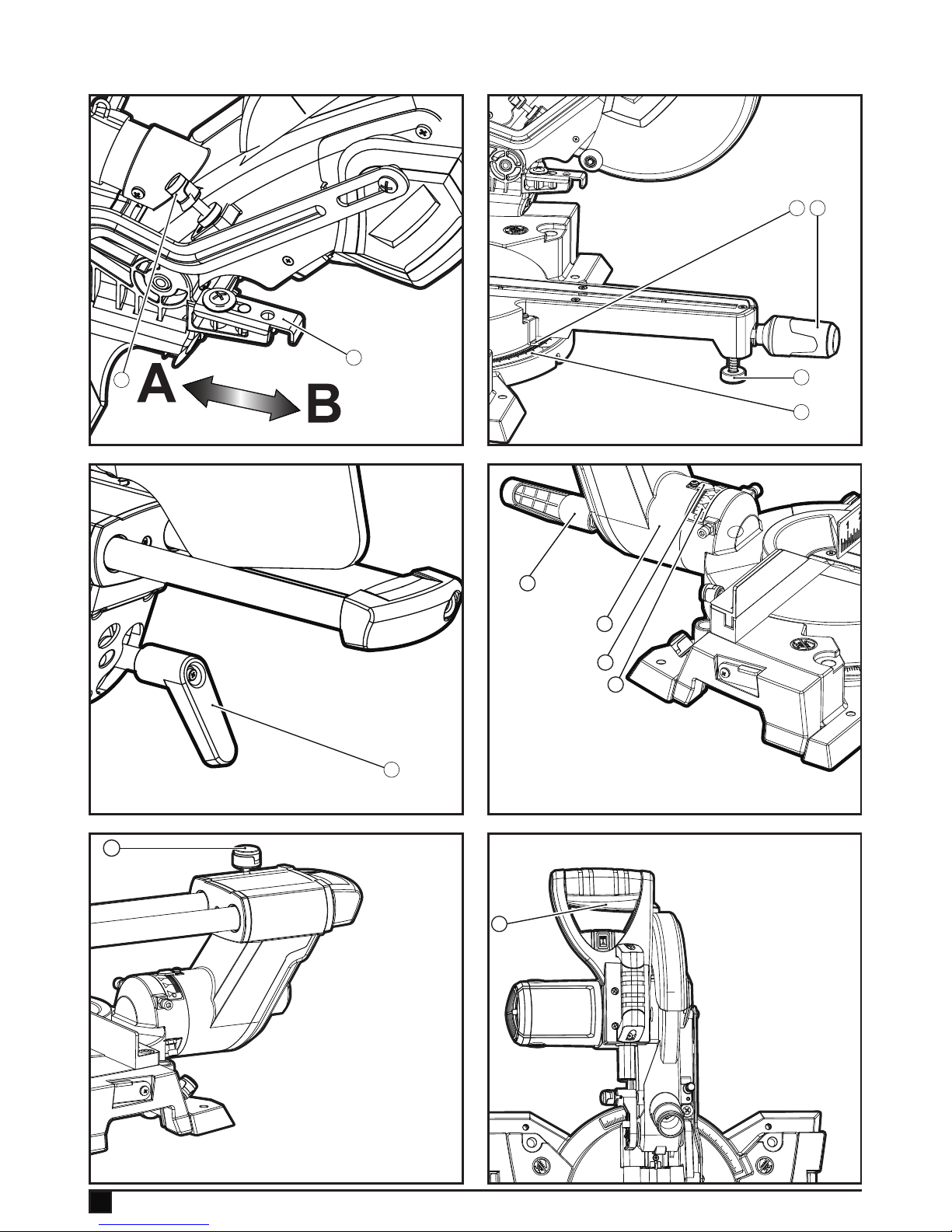
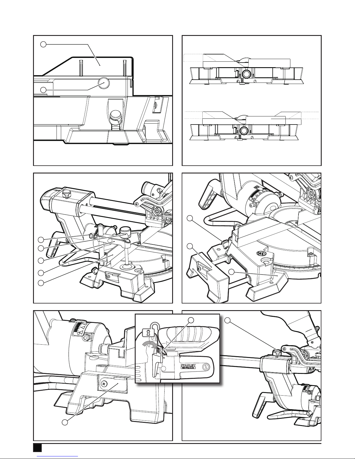
Adjusting the stopper arm (Fig.7)
The lower limit position of the blade can be easily adjusted
with the stopper arm (31).
u Move the stopper arm in the direction of the arrow as
shown (Fig.7) .
u Adjust it to position A for full cutting.
u Adjust the cutting depth limter (23) so that the blade stops
at the desired position when lowering the handle fully.
u Adjust it to position B for dado cutting .
u Adjust the cutting depth limter (23) so that the blade stops
at the desired position when lowering the handle.
Adjusting the mitre angle (Fig.8)
u Loosen the grip (21) by turning counterclockwise.
u When you have moved the grip (21) to the position where
the pointer (32) points to the desired angle on the mitre
scale (33), tighten the grip clockwise.
u The height adjustable foot (22) is to help keep the tool in
balance. After each mitre angle adjustment, you should
turn knob on the foot clockwise or counterclockwise until
its bottom touches the ground.
Adjusting the bevel angle (Fig.9, Fig10)
When tilting the carriage to the left, loosen the lever (10) at the
rear of the tool counterclockwise. Unlock the arm by pushing
the handle somewhat strongly in the direction that you intend
to tilt the saw blade.
u Tilt the saw blade until the pointer (34) points to the
desired angle on the bevel scale (35).
u Tighten the lever (10) clockwise rmly to secure the arm
(36).
Warning: When tilting the saw blade, be sure to raise the
handle fully. After changing the bevel angle, always secure the
arm by tightening the lever clockwise.
Page 15

15
ENGLISH
(Original instructions)
Slide lock adjustment (Fig.11)
To unlock the track arm, turn the track arm lock knob (6)
counterclockwise or clockwise.
Switch action (Fig.12)
Caution! Before plugging in the tool, always check to see that
the switch trigger (37) actuates properly and returns to the
"OFF" position when released.
u To start the tool, press the switch trigger (37).
u To stop the tool, release the switch trigger (37).
Warning: Never use tool without a fully operative switch
trigger. Any tool with an inoperative switch is HIGHLY
DANGEROUS and must be repaired before usage.
Electronic Function. Laser beam action (Fig.13)
Caution! When not in use, be sure to turn off the laser.
Never look into the laser beam directly; lase beam may injure
your eyes.
LASER RADIATION: DO NOT STARE INTO THE BEAM or
any CLASSII LASER PRODUCTS.
Before shifting the laser line or performing maintenance
adjustment, be sure to unplug the tool.
u To turn on the laser beam, press the upper position (I) of
the switch .
u To turn off the laser beam, press the lower position (O) of
the switch.
The laser line is factory adjusted so that it is positioned 1mm
from the side surface of the blade (cutting position).
Cleaning of the lens for the laser light
If the lens for the laser light becomes dirty, or sawdust adheres to it in such a way that the laser line is no longer easily
visible, unplug the saw and clean the lens carefully with a
damp, soft cloth. Do not use solvents or any petroleum based
cleaners on the lens.
Note: When laser line is dim and almost or entirely invisible
because of the direct sunlight in the indoor or outdoor window
near your work area, relocate the work area to a place not
exposed to direct sunlight.
Note: All of the adjustments for the operation of this machine
have been carried out at the factory.
Caution: Use of controls or adjustments or performance of
procedures other than those specied herein may result in
hazardous radiation exposure. The use of optical instruments
with this product will increase eye hazard. Do not attempt to
repair or disassemble the laser. If unqualied persons attempt
to repair this laser product, serious injury may result. Any
repair required on this laser product should be performed by
authorised service centre personnel.
Installing or removing saw blade (Fig.14, Fig.15,
Fig.16)
Caution: Always be sure that the tool is switched off and un-
plugged before installing or removing the blade. Use only the
wrench provided (38) to install or remove the blade. Failure to
do so may result in over tightening or insufcient tightening of
the screw. This may result in injury.
Fig.15
u To remove the blade, use cross screwdriver to loose the
screw (39) holding the centre cover by turning it counter-
clockwise and loosen the screw (29) counterclockwise, but
don't remove it.
u Turn the centre cover (40) counterclockwise and raise the
blade guard.
u Press the shaft lock (25) (Fig 14) to lock the spindle and
use the wrench (38) to loosen the screw (41) clockwise.
u Then remove the screw (41), outange (42) and blade
(30).
Note! When inner ange (43) is removed mistakenly, be sure
to install it on the spindle with its at surface facing the motor.
Fig.16
To install the blade, mount it carefully onto the spindle, making
sure that the direction of the arrow on the surface of the blade
(30) matches the direction of the arrow (44) on the blade case.
Install the outer ange and screw, and then use the wrench
to tighten the screw securely counterclockwise while pressing
the shaft lock.
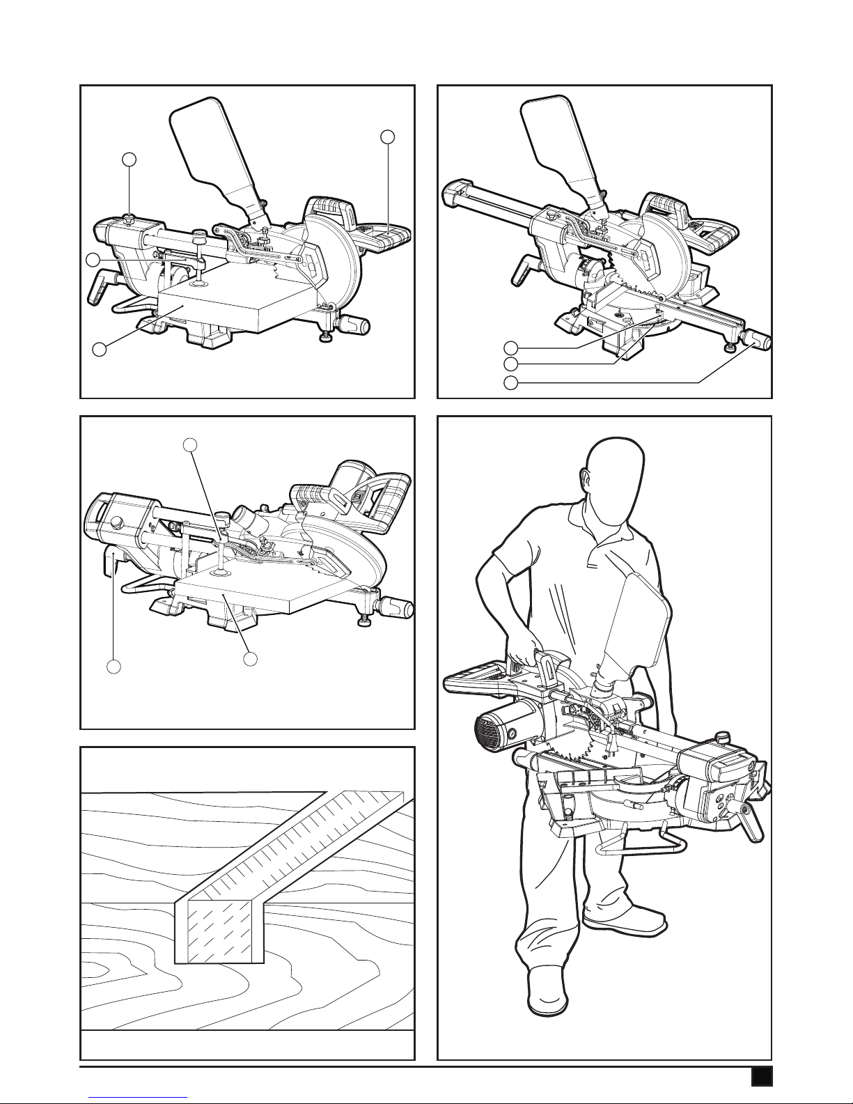
Dust bag (accessory) (Fig.17)
The use of the dust bag (5) makes cutting operations clean
and dust collections easy.
u To attach the dust bag (5), t it onto the dust nozzle(14).
u When the dust bag (5) is about half full, remove it from the
tool and pull the fastener (45) out.
u Empty the dust bag of its contents, tapping it lightly so as
to remove particles adhering to the insides which might
hamper further collection.
Note! If you connect a vacuum cleaner to your saw, more
efcient and cleaner operations can be performed.
Securing work piece (Fig.18)
Warning! It is extremely important to always secure the work
piece properly and tightly using a material clamp. Failure to do
so can cause the tool to be damaged and/or the work piece to
be destroyed. PERSONAL INJURY MAY ALSO RESULT. After
a cutting operation, DO NOT raise the blade until the blade
has come to a complete stop. When cutting a long work piece,
use supports (46) that are as high as the top surface level of
the turn table (18).
Caution! Do not rely solely on the vertical material clamp to
secure the work piece.
Page 16

16
ENGLISH
(Original instructions)
Thin material tends to sag. Support work piece over its entire
length to avoid blade pinch and possible kickback.
Sliding sub-fence adjustment (left) (Fig.19, Fig.20,
Fig. 21)
Sub-fence (left) Before left bevel cutting, make sure that no
part of the tool contacts the sliding fence (9) when lowering
and raising the handle fully at any position and pulling or
pushing the carriage all the way at the lowest position. Before
operating the tool, make sure that the sliding fence is secured
by the clamping knob (47) rmly.
Warning! When performing left bevel cuts, slide the sliding
fence to the left and secure it as shown (Fig.20). Otherwise,
it will contact the blade or a part of the tool, causing possible
serious injury to the operator. This tool is equipped with the
sliding fence which should ordinarily be positioned as shown
in (Fig.19). However, when performing left bevel cuts, set it to
the left position as shown in (Fig.20) if the tool head contacts
it. When bevel cutting operations are complete, don't forget
to return the sliding fence to the original position (Fig.19) and
secure it by rmly tightening the knob.
Material clamp (Fig.22)
The vertical material clamp can be installed on either the left
or right side of the guide fence (9). Insert the material clamp
rod (48) into the hole behind fence (9). Position the material
clamp arm according to the thickness and shape of the work
piece and secure the material clamp arm (17) by tightening
the knob (49). If the material clamp arm contacts the guide
fence (9) or sub fence, adjust the material clamp arm to the
upper position. Make sure that no part of the tool contacts
the material clamp when lowering the handle fully and pulling
or pushing the carriage all the way. If some part contacts the
material clamp, re-position the material clamp. Press the work
piece at against the guide fence and the turn base. Position
the work piece at the desired cutting position and secure it
rmly by tightening the material clamp knob (50).
Caution! The work piece must be secured rmly against the
turn base and guide fence with the material clamp during all
operations.
Extension table (Fig.23)
Unlock the knobs(51) on the base (19). Slide the left extension
table (12) to the desired table width and stop the extension
table by locking the knobs (51). Slide the right extension table
by the same amount as above.
Stock stop (Fig.24)
When you want to cut the work piece as the same length size
constantly, you can use the stock stop device to guarantee it.
Make sure the stock stop (13) on the left and right extension
table can be swung up as illustrated.
Guard release lever (Fig.24a)
The guard release lever (A) serves to lock the blade guard.
Blade guard will remain locked until the guard release lever
(A) has been turned to one side.
Operating instructions
Caution! Before use, be sure to release the handle from the
lowered position by pulling the stopper pin. Make sure the
blade is not contacting the work piece before the switch is
turned on. Do not apply excessive pressure on the handle
when cutting. Too much force may result in the motor over-
loading and/or decreased cutting efciency. Push down handle
with only as much force as is necessary for smooth cutting,
without a signicant decrease in blade speed. Gently press
down the handle to perform the cut. If the handle is pressed
down with force or if lateral force is applied, the blade will
vibrate and leave a mark (saw mark) in the work piece and the
precision of the cut will be impaired. During a slide cut, gently
push the carriage toward the guide fence without stopping. If
the carriage movement is stopping during the cut, a mark will
be left in the work piece and the precision of the cut will be
impaired.
Press cutting (cutting small work pieces) (Fig.25)
Work pieces up to 70mm high and 90mm wide can be cut in
the following way:
u Push the carriage toward the guide fence fully and tighten
the track arm lock knob (6) clockwise to secure the car-
riage.
u Secure the work piece with the material clamp.
u switch on the tool without the blade making any contact
and wait until the blade attains full speed before lowering.
u Then gently lower the handle to the fully lowered position
to cut the work piece.
u When the cut is complete, switch off the tool and wait until
the blade has come to a complete stop before returning
the blade to its fully elevated position.
Caution! Firmly tighten the track arm lock knob clockwise so
that the carriage will not move during operation. Insufcient
tightening may cause unexpected kickback of the blade. Pos-
sible serious personal injury may result.
Slide (push) cutting (cutting wide work pieces) (Fig.
26)
u Loosen the track arm lock knob (6)counterclockwise so
that the carriage can slide freely.
u Secure the work piece (52) with the material clamp (17).
Page 17

17
ENGLISH
(Original instructions)
u Pull the carriage toward you fully.
u Switch on the tool without the blade making any contact
and wait until the blade gets up to full speed.
u press down the handle (1) and push the carriage toward
the guide fence. And through the workpiece.
u When the cut is completed, switch off the tool and wait
until the blade has come to a complete stop before return-
ing the blade to its fully elevated position.
CAUTION: When performing a slide cut, pull the carriage toward you fully and press down the handle to the fully lowered
position, then push the carriage toward the guide fence. Never
start the cut with the carriage not fully pulled toward you.
If you perform the slide cut without pulling the carriage fully
or if you perform the slide cut towards you, the blade may
kickback unexpectedly with the potential to cause serious
personal injury. Never perform the slide cut with the handle
locked in the lowered position by pressing the stopper pin.
Mitre cutting (Fig.27)
u Loosen the grip (21) by turning counterclockwise.
u When you have moved the grip (21) to the position where
the pointer (32) points to the desired angle on the mitre
scale (33), securely tighten the grip clockwise.
Caution! When turning the turn base, be sure to raise the
handle fully. After changing the mitre angle, always secure the
turn base by tightening the grip rmly.
Bevel cutting (Fig.28)
u Loosen the lever (10) and tilt the saw blade to set the
bevel angle (refer to the previous section "Adjusting the
bevel angle"). Be sure to retighten the lever (10) rmly to
secure the selected bevel angle.
u Secure the work piece (52) with the material clamp (17).
u Make sure the carriage is pulled all the way back toward
the operator fully.
u Switch on the tool without the blade making any contact
and wait until the blade attains full speed.
u Then gently lower the handle to the fully lowered position
while applying pressure in parallel with the blade and push
the carriage toward the guide fence to cut the work piece.
u When the cut is completed switch off the tool and wait until
the blade has come to a complete stop before returning
the blade to its elevated position.
Caution! Always be sure that the blade will move down to
bevel direction during a bevel cut. Keep your hands out of
the path of the saw blade. During a bevel cut, it may create a
condition whereby the piece cut off will come to rest against
the side of the blade. If the blade is raised while the blade is
still rotating, this piece may be caught by the blade , causing
fragments to be scattered, which is dangerous. The blade
should be raised only after the blade has come to a complete
stop. When pressing down the handle, apply pressure in
parallel with the blade. If a force is applied perpendicularly to
the turn base or if the pressure direction is changed during a
cut, the precision of the cut will be diminished.
Always slide or remove the sliding fence (left) so that it does
not interfere with any part of the carriage when performing
bevel cuts.
Compound cutting
Compound cutting is the process in which a bevel angle is
made at the same time in which a mitre angle is being cut.
Compound cutting can be performed at the angles shown in
the below table.
Mitre angle Bevel angle
Left and Right 0° ~ 45° Left ~ 45°
When performing compound cutting, refer to the "Press cutting", "Slide cutting", "Mitre cutting" and "Bevel cutting sections
of this manual.
Groove cutting (Fig.29)
A dado type cut can be made by proceeding as follows:
u Adjust the lower limit position of the blade using the ad-
justing screw and the stopper arm to limit the cutting depth
of the blade . refer to the "Stopper arm" section described
previously.
u After adjusting the lower limit position of the blade, cut
parallel grooves across the width of the work piece using a
slide (push) cut as shown in figure.
u Then remove the work piece material between the
grooves with a chisel.
u Do not attempt to perform this type of cut using wide
(thick) blades or with a dado blade. Possible loss of
control and injury may result .
Caution! Be sure to return the stopper arm to the original position when performing an operation other than groove cutting.
Carrying the tool (Fig.30)
u Make sure the tool is unplugged.
u Secure the blade at the 0° bevel angle and turn the base
to the right mitre angle fully.
u Secure the slide poles after pulling the carriage toward
you fully.
u Lower the handle fully and lock it in the position by push-
ing in the stopper pin.
u Carry the tool by holding the base as shown in the gure.
u If you remove the material clamp, dust bag, etc., you can
carry the tool more easily.
u Carry the tool by one hand holding the carrying handle
and one hand holding the tool base.
Caution! Always secure all moving portions before carrying
Page 18

18
ENGLISH
(Original instructions)
the tool.
Stopper pin is for carrying and storage purposes only and not
for any cutting operations.
Maintenance
Caution! Always be sure that the tool is switched off and
unplugged before attempting to perform inspection and
maintenance.
Warning! Always be sure that the blade is sharp and clean for
the best and safest performance.
Note! Never use gasoline, benzene, thinner, alcohol or similar
substances. Discolouration, deformation or cracks may result.
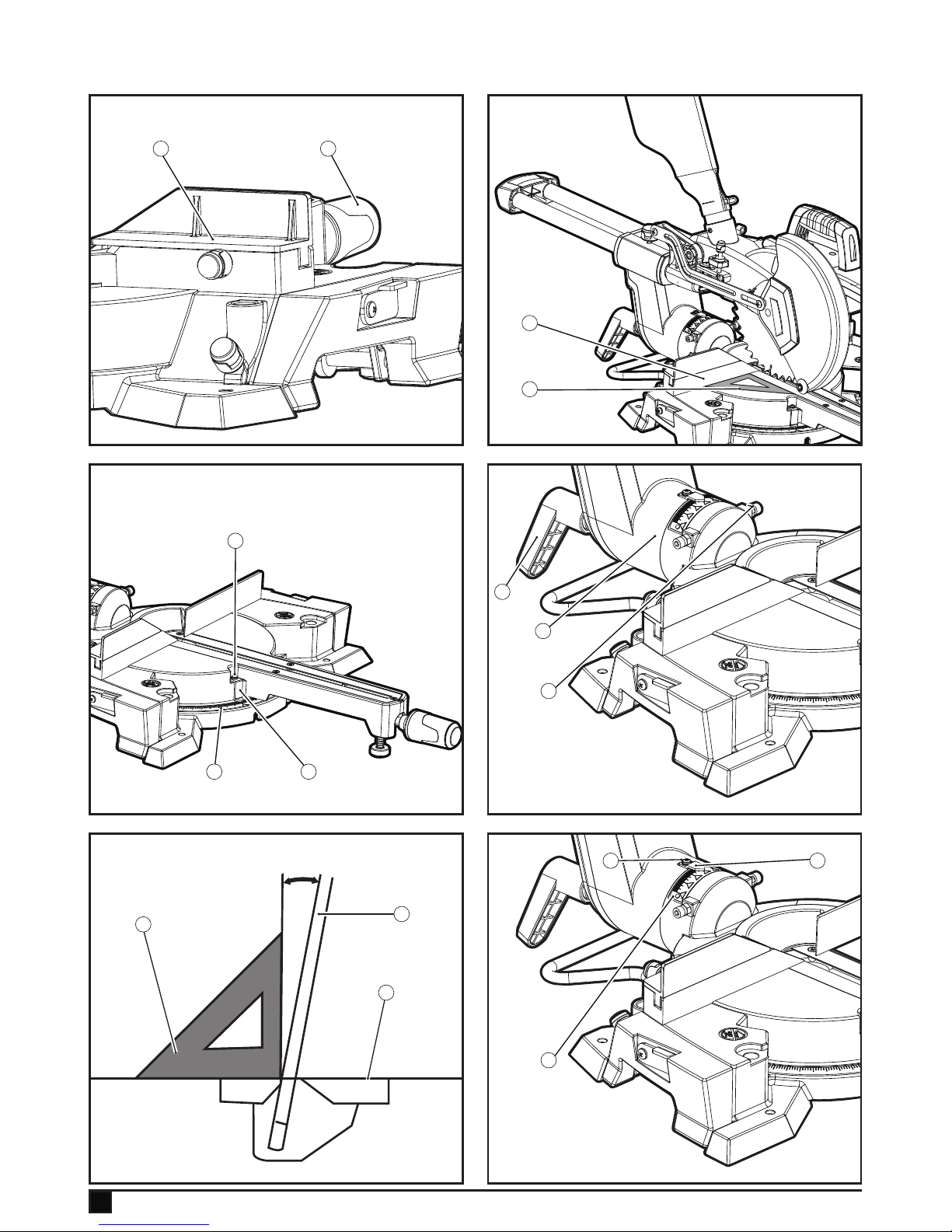
Adjusting the cutting angle (Fig.31, Fig.32, Fig.33)
This tool is carefully adjusted and aligned at the factory, but
rough handling may have affected the alignment. If your tool is
not aligned properly, perform the following.
Mitre angle (Fig.31)
u Push the carriage toward the guide fence (9) and tighten
the locking screw to secure the carriage. Loosen the grip
(21) which secures the turn base. Turn the turn base
so that the pointer points to 0º. Then turn the turn base
slightly clockwise and counterclockwise to seat the turn
base in the 0º mitre notch.
Fig.32
u Lower the handle fully and lock it in to the lowered position
by pushing in the stopper pin.
u Square the side of the blade with the face of the guide
fence (9) using a triangular rule (53), tri-square etc.
Fig.33
u Make sure that the pointer (32) points to 0º on the mitre
scale (33). If the pointer (32) does not point to 0º, loosen
the screw (54) which secures the pointer (360 and adjust
the pointer (32) so that it will point to 0º.
Bevel angle (0° bevel angle Fig.34, Fig.35, Fig.36)
u Push the carriage toward the guide fence and tighten the
locking screw to secure the carriage.
u Lower the handle fully and lock it in the lowered position
by pushing in the stopper pin.
u Loosen the lever (10) at the rear of the tool.
u Carefully square the side of the blade (30) with the top
surface of the turn table (18) using a triangular rule (53),
tri-square, etc.
u Turn the hex bolt (54) on the arm (36) slightly counter-
clockwise or clockwise to tilt the blade to the right position.
u Then tighten the lever securely.
u Make sure that the pointer (34) on the arm points to 0º on
the bevel scale (35) on the arm holder.
u If they do not point to 0º, loosen the screw (55) which
secures the pointer (34) and adjust it so that it will point to
0º.
45° Bevel angle (Fig.37, Fig.38)
u Adjust the 45º bevel angle only after performing 0º bevel
angle adjustment.
u To adjust left bevel angle, loosen the lever (10) and tilt the
blade to the left fully.
u Carefully measure the angle of the side of the blade (30)
with the top surface of the turn table (18) using the 45º
triangular rule (53).
u Turn the left 45º bevel angle adjusting bolt on the arm
(36) slightly counterclockwise to tilt the blade to the right
position.
u Then tighten the lever securely.
u Make sure that the pointer (34) an the arm points to 45º.
u If the pointer does not point to 45º, adjust the pointer to
45º on the scale by loosening the screw (55), and then
tighten the screw.
After use
u After use, wipe off chips and dust adhering to the tool with
a cloth or the like.
u keep the blade guard clean according to the directions in
the previously covered section "Retractable blade guard"
on Page. 14".
u Lubricate the sliding portions with machine oil to prevent
rust.
u When storing the tool, pull the carriage toward you fully.
Troubleshooting
Problem Possible Cause Solution
Motor does not start Saw not plugged in Check that all cords
are plugged in
Angle of cut
inaccurate
Mitre table unlocked Use mitre table
locking lever (see
Adjusting the mitre
angle section on
Page .15)
Too much sawdust under
table
Vacuum or blow out
dust. Wear eye
protection
Cutting arm cannot
fully raise, or blade
guard cannot fully
close
Parts Failure Contact service
centre
Pivot spring not replaced
properly after service
Contact service
centre
sawdust build up Clean and lubricate
moving parts
Saw head locking pin not
set properly
Check, adjust, and
properly set saw
head locking pin
Page 19

19
ENGLISH
(Original instructions)
Problem Possible Cause Solution
Blade binds, jams or
shakes
Saw blade damaged Replace blade
Dull blade Replace or sharpen
blade
Improper blade Replace blade
Warped blade Replace blade
Saw vibrates or
shakes
Saw blade damaged Replace blade
Saw blade loosened Tighten arbor bolt
Saw not properly fastened
down
Fasten saw to bench,
stand or table
Work piece not properly
supported
properly support or
clamp work piece
Laser line projection
is hard to see
Light in work area is too
bright
Move the mitre saw
to a work area with
proper light
Saw dust on the laser lens Clean laser lens with
a soft, dry brush
Protecting the environment
Z
Separate collection. This product must not be
disposed of with normal household waste.
Should you nd one day that your Stanley Fat Max product
needs replacement, or if it is of no further use to you, do not
dispose of it with household waste. Make this product available for separate collection.
z
Separate collection of used products and packaging allows materials to be recycled and used again.
Re-use of recycled materials helps prevent
environmental pollution and reduces the demand
for raw materials.
Local regulations may provide for separate collection of electrical products from the household, at municipal waste sites or
by the retailer when you purchase a new product.
Stanley Europe provides a facility for the collection and
recycling of Stanley Fat Max products once they have reached
the end of their working life. To take advantage of this service
please return your product to any authorised repair agent who
will collect them on our behalf.
You can check the location of your nearest authorised repair
agent by contacting your local Stanley Europe ofce at
the address indicated in this manual. Alternatively, a list of
authorised Stanley Europe repair agents and full details of our
after-sales service and contacts are available on the Internet
at: www.2helpU.com
Technical data
FME721
Motor 230V~50Hz, 1500W S6 20%
5min
Speed 5000RPM
Blade 216mm (40 tooth) carbide
tipped
Laser Class ll
Laser wavelength 650nm
Laser outpower <1mW
Net weight 16.6kg
Cutting capacity 6.2 x 30.5cm crosscut at 0º
mitre, 0º bevel
6.2 x 21.5cm mitre at 45º mitre,
0º bevel
3 x 30.5 cm bevel at 0º mitre,
45º bevel
3 x 21.5cm compound at 45º
mitre, 45º bevel
LpA (sound pressure) 99dB(A), Uncertainty (K) 3dB(A)
L
WA
(sound power) 111dB(A), Uncertainty (K) 3dB(A)
Vibration total values (triax vector sum) according to EN 61029:
Vibration emission value (a
h
) 4.8m/s2, uncertainty (K) 1.5 m/s
2
EC declaration of conformity
MACHINERY DIRECTIVE
%
FME721 Sliding Compound Mitre Saw
Stanley Europe declares that these products described under
"technical data" are in compliance with:
Page 20

20
ENGLISH
(Original instructions)
2006/42/EC, EN 61029-1, EN 61029-2-9
These products also comply with Directive 2004/108/EC and
2011/65/EU. For more information, please contact Stanley
Europe at the following address or refer to the back of the
manual.
The undersigned is responsible for compilation of the technical
le and makes this declaration on behalf of Stanley Europe.
Ray Laverick
Engineering Manager
Stanley Europe, Egide Walschaertsstraat14-18,
2800 Mechelen, Belgium
26/01/2015
Guarantee
Stanley Europe is condent of the quality of its products
and offers an outstanding guarantee for professional users
of the product. This guarantee statement is in addition to
and in no way prejudices your contractual rights as a private
non-professional user. The guarantee is valid within the territories of the Member States of the European Union and the
European Free Trade Area.
ONE-YEAR FULL WARRANTY
If your Stanley Fat Max product becomes defective due to
faulty materials or workmanship within 12 months from the
date of purchase, Stanley Europe guarantees to replace all
defective parts free of charge or – at our discretion – replace
the unit free of charge provided that:
u The product has not been misused and has been used in
accordance with the instruction manual.
u The product has been subject to fair wear and tear;
u Repairs have not been attempted by unauthorised per-
sons;
u Proof of purchase is produced.
u The Stanley Fat Max product is returned complete with all
original components
If you wish to make a claim, contact your seller or check the
location of your nearest authorised Stanley Fat Max repair
agent in the Stanley Fat Max catalogue or contact your local
Stanley ofce at the address indicated in this manual. A list
of authorised Stanley Fat Max repair agents and full details
of our after sales service is available on the internet at: www.
stanley.eu/3
Page 21

21
21
ENGLISH
(Original instructions)
Page 22

22
Page 23

23
Page 24

90625440-PDF1 REV-0
06/2015
United Kingdom
Stanley Fat Max Tel. 01753 511234
210 Bath Road Fax 01753 572112
Slough, Berkshire SL1 3YD www.stanleytools.co.uk
 Loading...