

Page 1
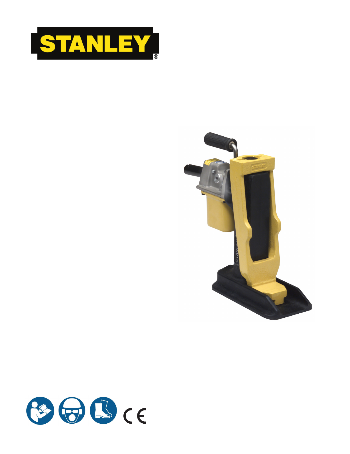
TJ10
HYDRAULIC
TRACK JACK
Safety, OperatiOn and Maintenance
USer'S ManUaL
© 2011 Stanley Black & Decker, Inc.
New Britain, CT 06053
U.S.A.
34964 4/2013 Ver. 8
Page 2
TABLE OF CONTENTS
Declaration of Conformity ......................................................................... 3
Maintenance & Care ............................................................................ 8 - 9
General ................................................................................................ 8
Cleaning .............................................................................................. 8
Hydraulic Fluid ..................................................................................... 8
Replacing Fluid When Necessary .................................................. 8
Annual Hydraulic Fluid Change ......................................................8
Purging Air ...................................................................................... 9
Operation ........................................................................................... 10-11
Pre-Operation Instructions ................................................................. 10
Raising A Load ................................................................................... 10
Lowering A Load ................................................................................ 10
Horizontal Operation .......................................................................... 10
Safety Precautions ..............................................................................5 - 6
Tool Stickers and Tags ......................................................................... 7
Specications ......................................................................................... 12
Troubleshooting ...................................................................................... 11
Pump Assy Illustration.............................................................................14
Base Illustration & Parts List ...................................................................13
Part List....................................................................................................15
Repair Kits...............................................................................................16
Warranty..............................................................See Below or Back Cover
To ll out a Product Warranty Recording form and for information on your warranty visit
Stanleyhydraulic.com and select the Warranty tab.
(Note: the warranty recording form must be submitted to validate the warranty).
SERVICING: This manual contains safety, and operation instructions. Stanley Hydraulic Tools
recommends that servicing of hydraulic tools, other than routine maintenance, must be performed by an authorized and certied dealer. Please read the following warning.
DANGER
SERIOUS INJURY OR DEATH COULD RESULT FROM THE IMPROPER
REPAIR OR SERVICE OF THIS TOOL.
REPAIRS AND / OR SERVICE TO THIS TOOL MUST ONLY BE DONE
BY AN AUTHORIZED AND CERTIFIED DEALER.
2 ► TJ10 User Manual
Page 3
DECLARATION OF CONFORMITY
Weisbeck, Andy
Directive/Standards
No.
Approved body
ASTM
B30.1-2009
Self
DECLARATION OF CONFORMITY
ÜBEREINSTIMMUNGS-ERKLARUNG
DECLARATION DE CONFORMITE CEE
DECLARACION DE CONFORMIDAD
Hydraulic Tools
DICHIARAZIONE DI CONFORMITA
______________________________________________________________________
I, the undersigned:
Ich, der Unterzeichnende:
Je soussigné:
El abajo firmante:
lo sottoscritto:
hereby declare that the equipment specified hereunder:
bestätige hiermit, daß erklaren Produkt genannten Werk oder Gerät:
déclare que l’équipement visé ci-dessous:
Por la presente declaro que el equipo se especifica a continuación:
Dichiaro che le apparecchiature specificate di seguito:
Surname and First names/Familiennname und Vornamen/Nom et prénom /Nombr e y apellido/Cognom e eno me
1. Category:
Kategorie:
Catégorie:
Categoria:
Categoria:
2. Make/Marke/Marque/Marca/Marca
3. Type/Typ/Type/Tipo/Tipo: TJ10111M, TJ10111MF, TJ10112M
4. Serial number of equipment:
Seriennummer des Geräts:
Numéro de série de l’équipement:
Numero de serie del equipo:
Matricola dell´attrezzatura:
Has been manufactured in conformity with
Wurde hergestellt in Übereinstimmung mit
Est fabriqué conformément
Ha sido fabricado de acuerdo con
E’ stata costruita in conformitá con
Richtlinie/Standards
Directives/Normes
Directriz/Los Normas
Direttiva/Norme
Machinery Directive
EN
EN
EN
Nr
Numéro
No
n.
2006/42/EC:2006
12100-1:2009
12100-2:2009
1492:2000+A1:2008
Stanley
Track Jack
All
Prüfung durch
Organisme agréé
Aprobado
Collaudato
Self
Self
Self
Self
5. Special Provisions: None
6. Representative in the Union: Patrick Vervier, Stanley Dubuis 17-19, rue Jules Berthonneau-BP 3406 41034 Blois Cedex, France.
Vertreter in der Union/Représentant dans l’union/Representante en la Union/Rappresentante presso l’Unione
Done at/Ort/Fait à/Dado en/Fatto a Stanley Hydraulic Tools, Milwaukie, Oregon USA
Signature/Unterschrift/Signature/Firma/Firma
Position/Position/Fonction/Cargo/Posizione Engineering Manager
Spezielle Bestimmungen:
Dispositions particulières:
Provisiones especiales:
Disposizioni speciali:
Date/Datum/le/Fecha/Data 3-22-11
TJ10 User Manual ► 3
Page 4
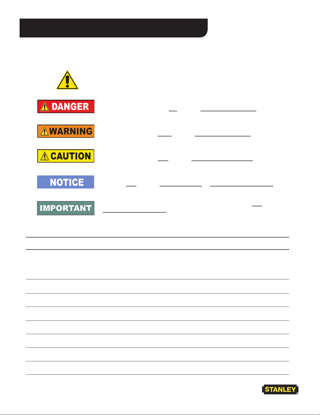
SAFETY SYMBOLS
Safety symbols and signal words, as shown below, are used to emphasize all operator, maintenance and repair
actions which, if not strictly followed, could result in a life-threatening situation, bodily injury or damage to equipment.
This is the safety alert symbol. It is used to alert you to potential personal
injury hazards. Obey all safety messages that follow this symbol to avoid
possible injury or death.
This safety alert and signal word indicate an imminently hazardous situation which, if not avoided, will result in death or serious injury.
This safety alert and signal word indicate a potentially hazardous situation
which, if not avoided, could result in death or serious injury.
This safety alert and signal word indicate a potentially hazardous situation
which, if not avoided, may result in minor or moderate injury.
This signal word indicates a potentially hazardous situation which, if not
avoided, may result in property damage or damage to the equipment.
This signal word indicates a situation which, if not avoided, may result in
damage to the equipment.
Always observe safety symbols. They are included for your safety and for the protection of the tool.
LOCAL SAFETY REGULATIONS
Enter any local safety regulations here. Keep these instructions in an area accessible to the operator and maintenance personnel.
4 ► TJ10 User Manual
Page 5
SAFETY PRECAUTIONS
Tool operators and maintenance personnel must always comply with the safety precautions given in this manual and
on the stickers and tags attached to the tool and hose.
These safety precautions are given for your safety. Review them carefully before operating the tool and before performing general maintenance or repairs.
Supervising personnel should develop additional precautions relating to the specic work area and local safety regu-
lations. If so, place the added precautions in the space provided.
GENERAL SAFETY PRECAUTIONS
• The user must be familiar with correct operation, maintenance, and use of the jack. Lack of knowledge can lead
to personal injury.
• Operator must start in a work area without bystanders. The operator must be familiar with all prohibited work
areas such as excessive slopes and dangerous terrain conditions..
• Always wear safety equipment such as goggles, gloves, head, and safety shoes at all times when operating the
tool.
• Warning: Hydraulic uid under pressure could cause skin injection injury. If you are injured by hydraulic uid,
get medical attention immediately.
• The total load lifted or supported by the jack must never exceed the rated capacity. Excess pressure can result in
personal injury. Use a jack with sufcient capacity to lift a load. Keep clear of lifted loads.
• Inspect each jack before each usage or shift to prevent unsafe conditions from developing.
• Properly support the jack.
• Do not put poorly balanced or off-center loads on the jack pad or jack. The load can tip and cause personal injury. Do not use in unstable or hazardous positions.
• The jack must be used on at surfaces to be able to carry the load correctly. The base must be completely supported. Do not push or lift on the ends of the base.
• Do not lift people, or loads with people on them.
• As the load is lifted, use blocks or cribs to guard against a falling load.
• To help prevent personal injury, do not allow personnel to go under, or work on, a load before it is properly
cribbed or blocked. All personnel must be clear of a load before lowering or lifting.
• Lift only dead weight loads. Do not add additional weight to a lifted load.
• Do not use jacks that are damaged, altered or in poor condition.
• The reservoir must have sufcient hydraulic uid to fully stroke the jack. Use only approved hydraulic uids.
• Read and understand the operating instructions in this manual, and the ASME B30.1 and EN 1494 safety code for
jacks.
• Users must ensure that all safety related decals and stickers are whole and readable. Replace those which become
unreadable.
TJ10 User Manual ► 5
Page 6

SAFETY PRECAUTIONS
GENERAL SAFETY PRECAUTIONS CONTINUED:
• Never use extreme heat to disassemble a hydraulic ram or cylinder. Metal fatigue can lead to unsafe conditions.
• Be aware of possible "pinch points" of the jack, and stay clear to avoid personal injury.
• When lifting with the edge of the lifting toe, place a wedge between the load and the top of the lifting toe to
avoid bending the cylinder column.
• Carry the jack only by the carrying handle. Make sure the jack is in the fully lowered position.
• End users must be trained in the proper use of the jack..
• Remove operating levers when not in use to avoid accidental dislocation of the jack, and reduce the tripping
hazard.
• Make sure all personnel are clear of the load before lifting or lowering.
• DO NOT use extenders unless authorized by a qualied person.
• Never use this tool when working around electried rail unless it is de-energized or you have been properly
trained to work on electried rail. If you are not sure the rail is live or not, you must treat it as being live and
dangerous to life.
6 ► TJ10 User Manual
Page 7
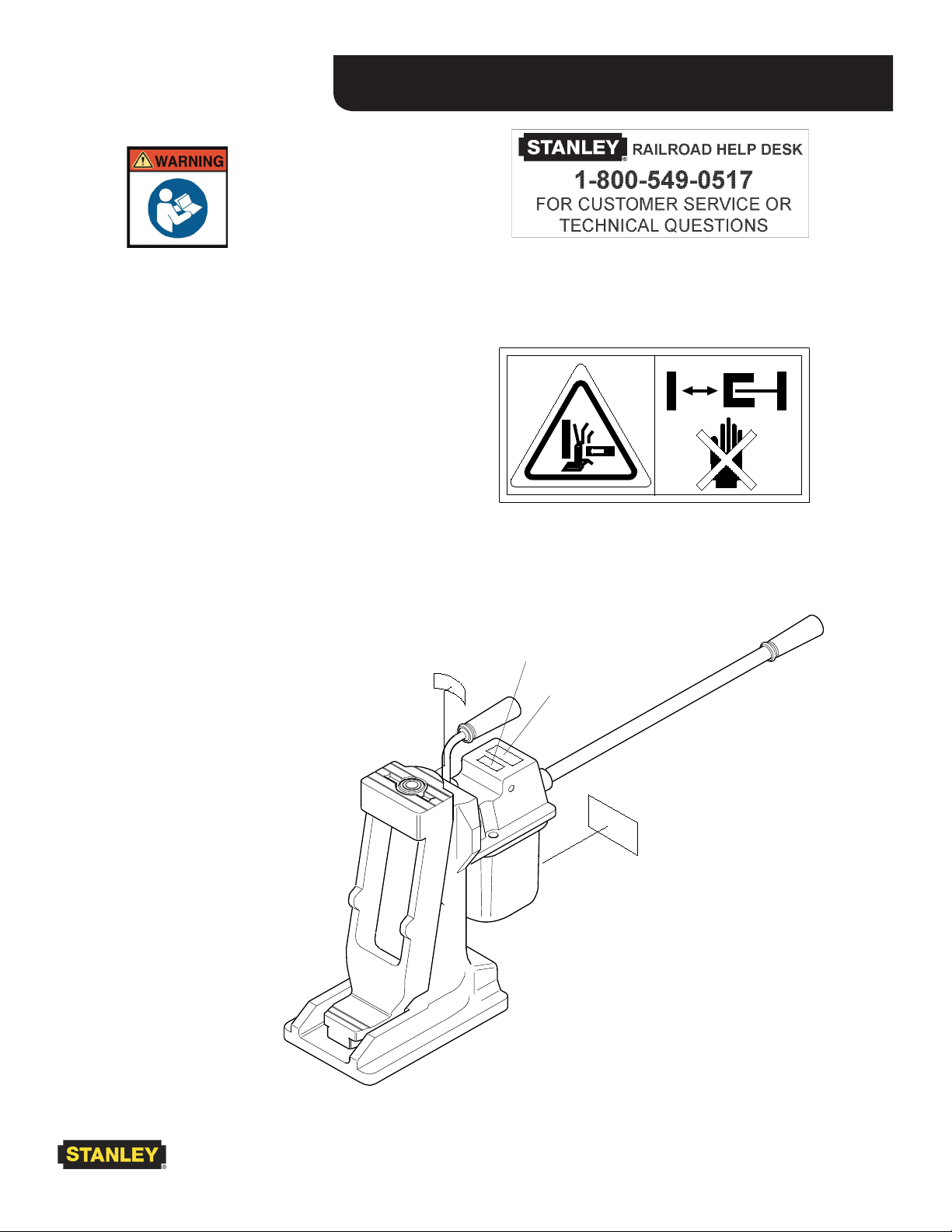
WARNING DECAL - P/N 28788
(Shown smaller than actual size)
Indicates that users should read
the manual before using the
product.
The following information is found on the base
of the Track Jack.
• ModelNumber
• Capacity
• MaximumPressure
• Date
TOOL STICKERS AND TAGS
RAILROAD HELP DESK - P/N 25610
CRUSH HAZARD - P/N 31064
P/N 31064
STICKER LOCATIONS
P/N 28788
P/N 25610
P/N 05152
TJ10 User Manual ► 7
Page 8
MAINTENANCE & CARE
GENERAL PROTECTION
Store the Track Jack in an upright position, in a place
where it is protected from the elements, abrasive dust,
and damage.
Use only recommended repair and replacement parts
and materials specied in the Parts List section of this
manual.
Do not use the jack for applications it was not designed
for.
Use the carrying handle to transport the Track Jack from
location to location. Do not carry the Track Jack by
inserting the jack handle in the socket.
CLEANING
Establish a routine to keep the jack as free from dirt as
possible – daily, or at each shift change, for example.
Jacks exposed to rain, sand, or grit-laden air should be
cleaned prior to each use.
Exposed screw threads should be cleaned and re-lubricated as necessary.
ADDING FLUID WHEN NEEDED
A jack that is low on hydraulic uid can lift a full load,
but not to the full lift height. As the reservoir begins to
run dry, the lever socket becomes very easy to pump,
and the jack stops lifting. To add oil:
1. Fully retract the plunger.
2. Remove the ll plug.
3. Fill the reservoir with new, clean uid (use ISO#15
Hydraulic Fluid) to a level 1/8 inch below the bottom of the ll plug hole.
WARNING
Do not overll or underll the reservoir
as this may damage the jack.
ANNUAL FLUID CHANGE
Regardless of usage, the Track Jack hydraulic uid
should be changed annually to ensure proper operation
of the jack. To drain the uid:
Keep the cylinder clean at all times. Keep the piston
retracted when not in use.
Operating lever and load-bearing surfaces should be
free of slippery material or uids.
Keep tool labels and stickers legible.
HYDRAULIC FLUID
The Track Jack holds approximately 28 ounces/820 cc
cubic inches of hydraulic uid in its reservoir.
DANGER
DO NOT USE BRAKE FLUID OR OTHER
NON-APPROVED SUBSTITUTE FLUIDS.
LIGHTER WEIGHT FLUIDS MAY CAUSE
THE JACK TO FAIL UNDER LOAD.
8 ► TJ10 User Manual
1. Thoroughly clean the area around the ll plug.
2. Remove the ll plug and lay the Track Jack on its
back to allow the uid to drain from the ll hole into
an appropriate receptacle.
3. Dispose of the used hydraulic uid in accordance
with Environmental Protection Agency regulations.
4. Make sure dirt or other contaminants do not enter
the reservoir while the ll plug is removed. When
drained, check the uid for contaminants. If the
uid appears gritty or dirty, ush the reservoir with
clean hydraulic uid before relling.
5. Rell the reservoir with the recommended hydraulic
uid. Stand the jack upright, and with the piston
fully retracted, ll the reservoir until the uid level
is 1/8 inch below the bottom of the ll plug.
6. Before returning the jack to service, fully extend the
piston without a load by pumping the pump handle
without the long extension handle. If the uid level
is correct, the pump handle will become almost impossible to pump by hand as the piston reaches full
extension. Replace the plug.
Page 9

7. It may be necessary to bleed air out of the cylinder.
See instructions below for purging air.
8. Inspect the jack for leaks, cracks, or other damage.
DANGER
Immediately take out of service any
jack that appears to be damaged or
PURGING AIR
Air trapped within the jack hydraulic system can be
removed by performing the following steps.
leaking.
MAINTENANCE & CARE
1. Make sure the plunger is fully retracted.
2. Pry out the cap on top of the unit.
3. Loosen (Do Not Remove) the capscrew under the
cap located in the top of the plunger.
4. Place the jack in a suitable xture to prevent the
extension of the plunger while purging air.
DANGER
The xture used to prevent extension
of the plunger while purging air must
be able to withstand the full ten ton
force of the jack.
5. Add hydraulic uid to the reservoir if necessary. See
instructions above for adding uid.
6. Pump the handle until oil comes up through the
thread area of the capscrew in the plunger.
7. Tighten the socket head capscrew to 10-12 ft.
lbs./14-16 Nm.
8. Top off the reservoir with hydraulic uid. NOTE:
Make sure the plunger is fully retracted before lling
the reservoir.
TJ10 User Manual ► 9
Page 10
OPERATING INSTRUCTIONS
DANGER
MAKE SURE THAT ALL PERSONNEL ARE CLEAR
OF THE LOAD BEFORE ATTEMPTING TO RAISE
OR LOWER THE JACK. SERIOUS INJURY OR
DEATH COULD RESULT FROM THE IMPROPER
USE OF THIS TOOL.
PREOPERATION PROCEDURES
Before putting a new Track Jack into initial service,
or after an extended period of being unused, perform
a visual inspection for bent, broken, cracked, missing
or worn components. Ensure the hydraulic uid and
lubricant level is correct. Fully extend and retract the
jack without a load to ensure that the jack is primed and
operating properly.
RAISING A LOAD
1. Before using the Track Jack, make sure that it is set
on a rm surface capable of bearing the intended
load.
WARNING
Use only the recommended length jack
handle. DO NOT use longer handles or
extenders.
5. Remove the jack handle from the handle socket once
the load reaches its desired height.
6. Crib or block the load to prevent accidently dropping the load.
LOWERING A LOAD
1. Make sure all personnel are clear of the load.
2. Remove cribbing or blocking if used.
3. Open the release valve by turning it counterclockwise (open slowly).
DANGER
2. Make sure the release valve is closed, by turning it
clockwise until it is hand tight.
DANGER
Overtightening the release valve can damage
the valve seat. DO NOT use pliers or wrenches
to tighten the release valve.
3. Pump the handle by hand until the toe lift or head
lift plate rises to and engages the load.
DANGER
Make certain that the lifting toe is fully
engaged on the load, and the entire jack is
stable, before proceeding further.
4. Insert the jack handle fully into the handle socket
and pump until the desired lift has been obtained.
Lowering speed is controlled by opening the
release valve more or less. DO NOT open the
valve more than two full turns.
4. When the load reaches the desired level, close the
release valve by turning it clockwise until it is hand
tight.
HORIZONTAL OPERATION
The Track Jack can also be used horizontally to separate
two items, as long as it is placed with the handle socket
facing upwards.
1. Place the Track Jack base against the largest, heaviest, or otherwise least moveable of the two items.
2. Close the release valve by turning it clockwise until
hand tight.
3. Pump the handle socket by hand until the lifting toe
or the head of the lifting toe rmly engages the more
moveable of the two items.
10 ► TJ10 User Manual
Page 11
TROUBLESHOOTING
4. Make sure personnel are clear of all items being
jacked before attempting to move anything.
WARNING
5. Insert the jack handle into the handle socket and
pump until the desired separation has been obtained.
6. Remove the jack handle from the socket once the
moveable load reaches its desired separation.
7. To free the jack, open the release valve by turning it
counterclockwise. When the lift plate is clear, close
the release valve.
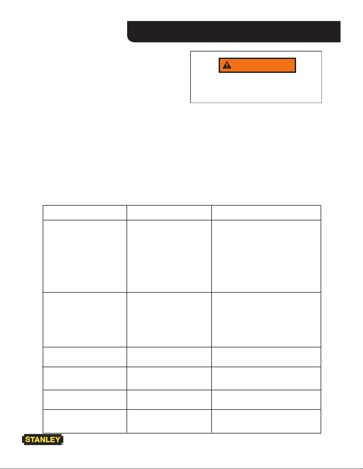
TROUBLESHOOTING
If symptoms of poor performance develop, the following chart can be used as a guide to correct the problem.
Because the Track Jack can be used for many different applications, this information is general in nature
anddoesnotaddressspecicuses.
NEVER LIFT OR LOWER A LOAD HEAVIER THAN
THE LOAD RATING OF THE JACK. DAMAGE
TO THE JACK OR LOAD COULD RESULT FROM
IMPROPER USE OF THIS TOOL.
PUMPING HANDLE
A pumping handle is included with the Track Jack is designed with a 4:1 safety factor. DO NOT use the pumping handle for any other purpose. DO NOT substitute
other material for use as a pumping handle.
PROBLEM CAUSE CORRECTION
Jack will not raise
Jack raises but will not hold Release valve ball not seat-
Jack only raises part way Hydraulicuidlevelislow Addhydraulicuid
Jackleakshydraulicuid Seal failure Havejackservicedbyaqualied
A) Release valve not closed
B) Release valve ball not
seating properly
C) Seal failure Havejackservicedbyaqualied
ing properly
Relief valve set too low or
Malfunctioning
Seal failure Havejackservicedbyaqualied
Close the valve
Havejackservicedbyaqualied
technician
technician
Havejackservicedbyaqualied
technician
technician
technician
Jack retracts slowly Air in the hydraulic system Purge air from the hydraulic system
Jack raises, but pulses and
hesitates
Air in the hydraulic system Purge air from the hydraulic system
TJ10 User Manual ► 11
Page 12

SPECIFICATIONS
Performance
MaximumLift ........................................................................................................................ 8.9 in. /226 mm
MaximumLoad .................................................................................................................... 10 tons/9070 kg
Pump Displacment ...............................................................................46 cu. in/7.5 cc stroke, single speed
Advance rate per stroke ..........................................................................................................14 in./3.6 mm
Pressure at rated load .............................. 7300 psi/500 bar Model TJ10, (7150 psi/493 bar Model TJ10M)
Maximumpumphandleeffort ...................................................................................................80 lbs./355 N
Dimensions and Weight
Baseplate Size..............................................................................................................6x11in./15x28cm
Lift Toe Width and Depth .............................................................................................2-1/2x3/63x76mm
Height (retracted) ..........................................14.5 in//37 cm Model TJ10, (14.75 in/37.5 cm Model TJ10M)
extended ......................................................23.4 in./59 cm Model TJ10, (23.56 in/60 cm Model TJ10M)
Net Weight (less oil) .................................................. 43 lb/20 kg Model TJ10, (44 lb/20 kg Model TJ10M)
Lever Bar Length ..................................................................................................................... 36 in./ 80 cm
Hydraulic Requirements
Reservoir Capacity .................................................................................................................. 28 oz/820 cc
Recommended Fluid ................................................................................................ISO #7 Hydraulic Fluid.
Standards ................................................................................................................. ASME B30.1, EN 1494
NOTE:Weights,dimensionsandoperatingspecicationslistedonthissheetaresubjecttochangewithoutnotice.Wherespecicationsarecriticaltoyourapplication,pleaseconsultthefactory.
12 ► TJ10 User Manual
Page 13

BASE ILLUSTRATION
TJ10 User Manual ► 13
Page 14

PUMP ASSY ILLUSTRATION
14 ► TJ10 User Manual
NOTE: Item descriptions which
are preceded by a item number
may be ordered individually.
NOTE: Item descriptions which are
preceded by a symbol are only available
in their respective repair kits.
Manifold Assembly P/N-34873
Includes all items shown except
pump handle 34870.
Page 15
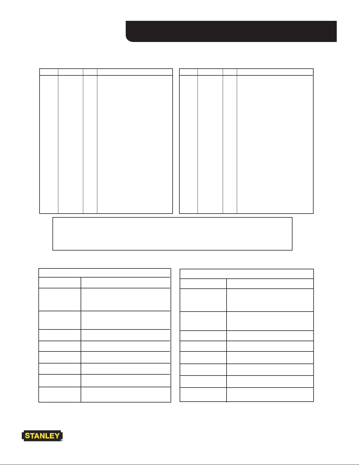
PARTS LIST
TJ10 *TJ10M
ITEM P/N QTY DESCRIPTION
1 52805 1 Cap
16 65924 1 Pumping Handle
28 01219 2 Pipe Plug
29 10888 4 Capscrew
40 34849 1 Relief Valve Assy
46 56629 1 Manifold
49 00769 4 Capscrew
50 31064 1 Sticker, Crush Hazard
52 05152 1 Sticker, Stanley Log
56 28788 1 Sticker, Manual Composite
57 25610 1 Sticker, Help Desk
59 34852 1 Piston
ITEM P/N QTY DESCRIPTION
1 52805 1 Cap
3 52806 1 Lifting Toe
6 52807 1 Stop Ring
11 52809 1 Plunger
14 52812 1 Base, (Model TJ10111M)
16 52813 1 Pumping Handle
28 01219 2 Pipe Plug
29 56518 4 Capscrew
38 52824 1 Seat Assy
40 52827 1 Relief Valve Assy
46 52830 1 Manifold
49 56521 4 Capscrew
50 31064 1 Sticker, Crush Hazard
52 05152 1 Sticker, Stanley Logo
56 28788 1 Sticker, Manual Composite
57 25610 1 Sticker, Help Desk
58 56601 1 Base (Narrow), (Model
TJ10112M)
59 52819 1 Piston
NOTE: When ordering parts make sure to check the (Model Number)
on your track jack to distinguish between a TJ10 and TJ10M*.
KITS FOR MODEL TJ10111 & TJ10112 ONLY
P/N DESCRIPTION
56629 Manifold Assy
34872 Cylinder Repair Kit
34858 Carry Handle Repair Kit
34851 Reservoir Repair Kit
34853 Beam & Piston Repair Kit
34848 Pump Repair Kit
34845 Release Valve Repair Kit
* KITS FOR MODEL TJ10111M & TJ10112M ONLY
P/N DESCRIPTION
56629 Manifold Assy
56528 Spring Kit
56522 Cylinder Repair Kit
56523 Carry Handle Repair Kit
56524 Reservoir Repair Kit
56525 Beam & Piston Repair Kit
56526 Pump Repair Kit
56527 Release Valve Repair Kit
* "M" Models Begin With S/N 5000.
TJ10 User Manual ► 15
Page 16

REPAIR KITS
16 ► TJ10 User Manual
Page 17

NOTES
TJ10 User Manual ► 17
Page 18
Stanley Hydraulic Tools
3810 SE Naef Road
Milwaukie, OR 97267-5698 USA
Phone: (503) 659-5660
Fax:(503)652-1780
www.stanleyhydraulic.com
Copyright© 2009 The Stanley Works
To ll out a Product Warranty Recording form and for information on your warranty visit
Stanleyhydraulic.com and select the Warranty tab.
(Note: the warranty recording form must be submitted to validate the warranty).
 Loading...