

Page 1
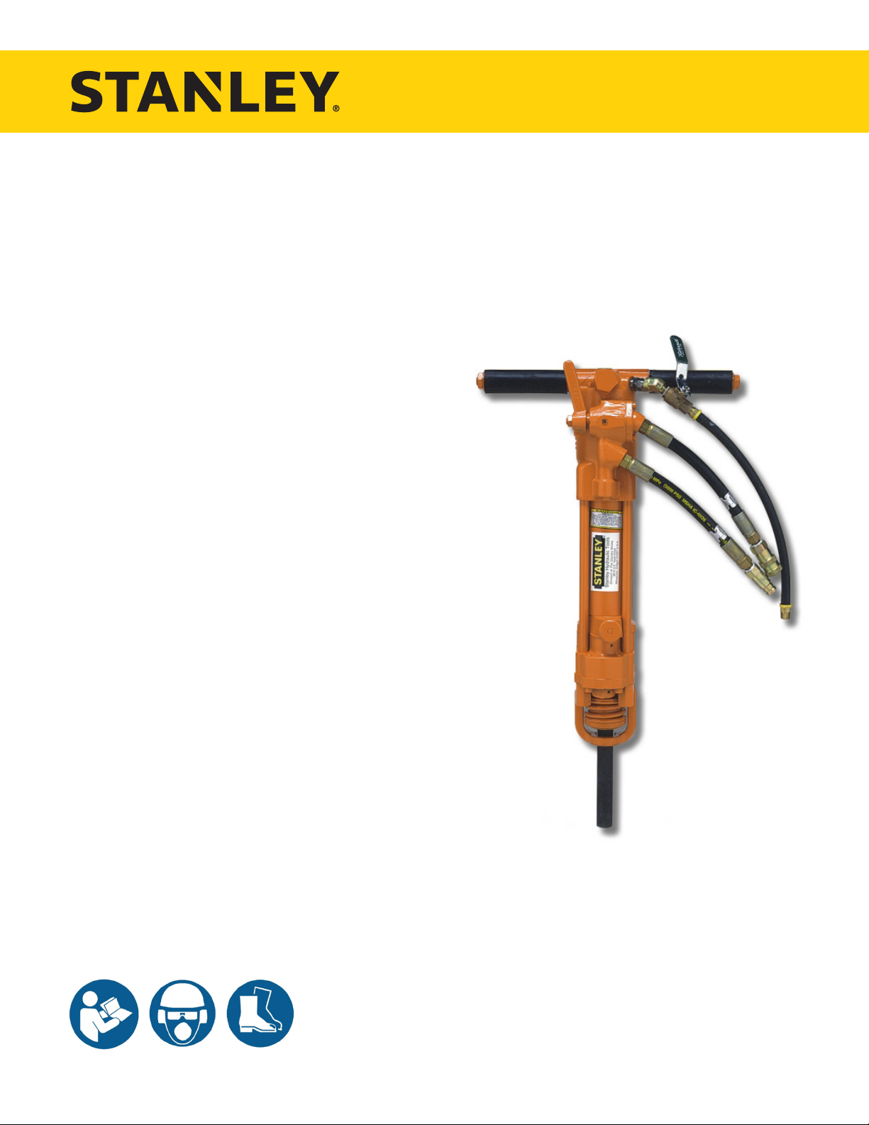
SK58
HYDRAULIC
SINKER DRILL
USER MANUAL
Safety, Operation and Maintenance
© 2014 Stanley Black & Decker, Inc.
New Britain, CT 06053
U.S.A.
70744 8/2014 Ver. 8
Page 2

Page 3
WARNING
IMPORTANT
TABLE OF CONTENTS
SAFETY SYMBOLS ..................................................................................................................................................4
SAFETY PRECAUTIONS .......................................................................................................................................... 5
TOOL STICKERS & TAGS ........................................................................................................................................6
HOSE TYPES ............................................................................................................................................................7
HOSE RECOMMENDATIONS ..................................................................................................................................8
FIGURE 1. TYPICAL HOSE CONNECTIONS .......................................................................................................8
HTMA REQUIREMENTS ...........................................................................................................................................9
OPERATION ............................................................................................................................................................10
TOOL PROTECTION & CARE ................................................................................................................................12
TROUBLESHOOTING ............................................................................................................................................13
CHARGING THE ACCUMULATOR .........................................................................................................................14
FIGURE 2. CHARGING THE ACCUMULATOR ................................................................................................... 15
SPECIFICATIONS ................................................................................................................................................... 16
ACCESSORIES.......................................................................................................................................................16
SERVICE TOOLS ....................................................................................................................................................16
SK58 PARTS ILLUSTRATION.................................................................................................................................17
SK58 PARTS LIST...................................................................................................................................................18
UNDERWATER TOOLS DEPTH GUIDELINE .........................................................................................................20
To ll out a Product Warranty Recording form, and for information on your warranty,
visit Stanleyhydraulics.com and select the Company tab, Warranty.
(NOTE: The warranty recording form must be submitted to validate the warranty).
SERVICING: This manual contains safety, operation, and routine maintenance instructions. Stanley Hydraulic Tools
recommends that servicing of hydraulic tools, other than routine maintenance, must be performed by an authorized
and certied dealer. Please read the following warning.
SERIOUS INJURY OR DEATH COULD RESULT FROM THE IMPROPER REPAIR OR
SERVICE OF THIS TOOL.
REPAIRS AND / OR SERVICE TO THIS TOOL MUST ONLY BE DONE BY AN
AUTHORIZED AND CERTIFIED DEALER.
For the nearest authorized and certied dealer, call Stanley Hydraulic Tools at the number listed on the back of this
manual and ask for a Customer Service Representative.
SK58 User Manual ◄ 3
Page 4
DANGER
WARNING
CAUTION
CAUTION
NOTICE
IMPORTANT
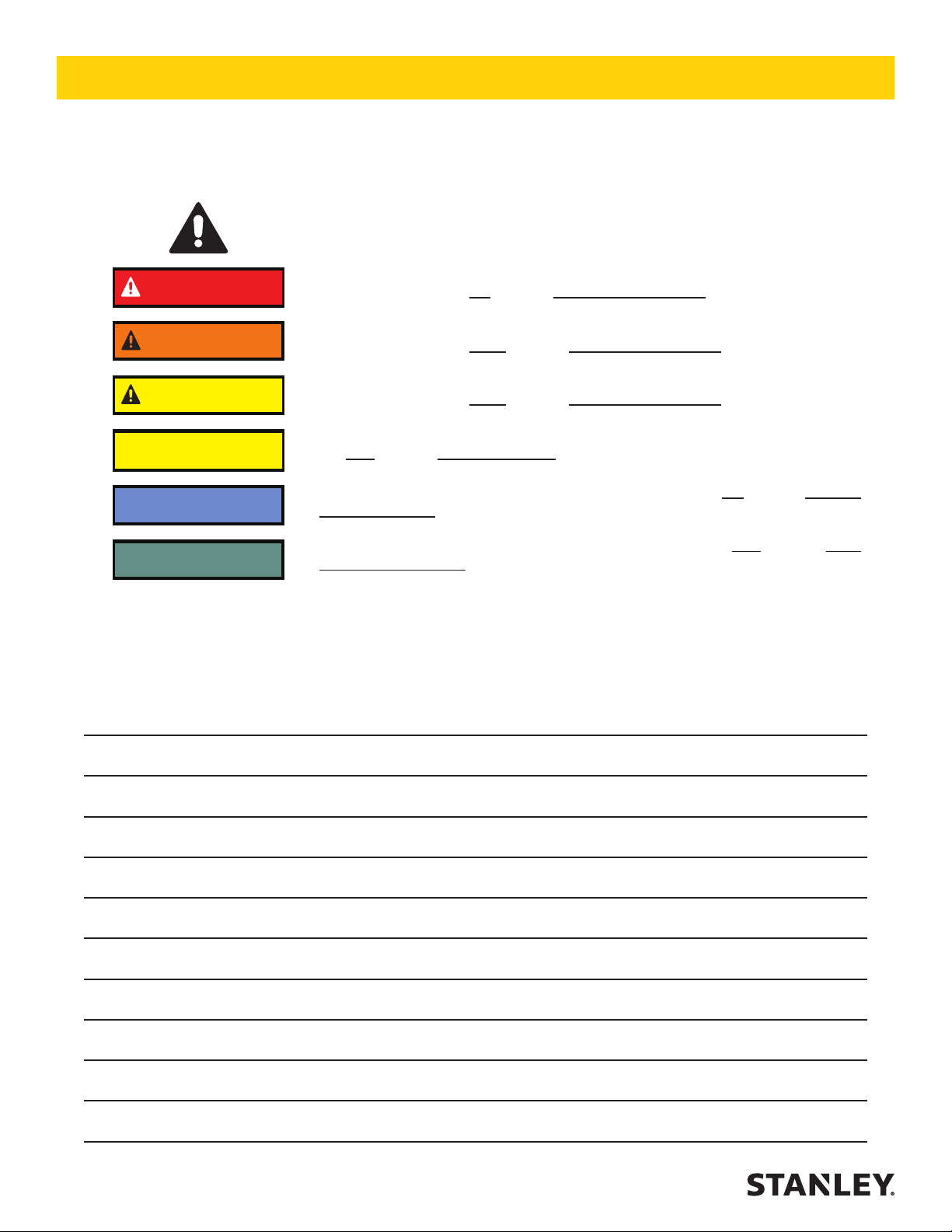
SAFETY SYMBOLS
Safety symbols and signal words, as shown below, are used to emphasize all operator, maintenance and repair actions which, if not strictly followed, could result in a life-threatening situation, bodily injury or damage to equipment.
This is the safety alert symbol. It is used to alert you to potential personal injury
hazards. Obey all safety messages that follow this symbol to avoid possible
injury or death.
This safety alert and signal word indicate an imminently hazardous situation
which, if not avoided, will result in death or serious injury.
This safety alert and signal word indicate a potentially hazardous situation
which, if not avoided, could result in death or serious injury.
This safety alert and signal word indicate a potentially hazardous situation
which, if not avoided, could result in death or serious injury.
This signal word indicates a potentially hazardous situation which, if not avoided, may result in property damage.
This signal word indicates a situation which, if not avoided, will result in damage
to the equipment.
This signal word indicates a situation which, if not avoided, may result in damage to the equipment.
Always observe safety symbols. They are included for your safety and for the protection of the tool.
LOCAL SAFETY REGULATIONS
Enter any local safety regulations here. Keep these instructions in an area accessible to the operator and maintenance personnel.
4 ► SK58 User Manual
Page 5

SAFETY PRECAUTIONS
Tool operators and maintenance personnel must always
comply with the safety precautions given in this manual
and on the stickers and tags attached to the tool and
hose.
These safety precautions are given for your safety. Review them carefully before operating the tool and before
performing general maintenance or repairs.
Supervising personnel should develop additional pre-
cautions relating to the specic work area and local
safety regulations. If so, place the added precautions in
the space provided in this manual.
The SK58 Hydraulic Sinker Drill will provide safe and
dependable service if operated in accordance with the
instructions given in this manual. Read and understand
this manual and any stickers and tags attached to the
tool and hoses before operation. Failure to do so could
result in personal injury or equipment damage.
• Operator must start in a work area without bystand-
ers. The operator must be familiar with all prohibited
work areas such as excessive slopes and dangerous terrain conditions.
• Establish a training program for all operators to en-
sure safe operation.
• Do not operate the tool unless thoroughly trained or
under the supervision of an instructor.
• Always wear safety equipment such as goggles,
ear, head protection, and safety shoes at all times
when operating the tool.
• Do not inspect or clean the tool while the hydraulic
power source is connected. Accidental engagement
of the tool can cause serious injury.
• Supply hoses must have a minimum working pres-
sure rating of 2500 psi/175 bar.
• Be sure all hose connections are tight.
• The hydraulic circuit control valve must be in the
“OFF” position when coupling or uncoupling the tool.
Wipe all couplers clean before connecting. Use only
lint-free cloths. Failure to do so may result in damage to the quick couplers and cause overheating of
the hydraulic system.
• Do not operate the tool at oil temperatures above
140 °F/60 °C. Operation at higher oil temperatures
can cause operator discomfort and may damage the
tool.
• Do not operate a damaged, improperly adjusted, or
incompletely assembled tool.
• Do not weld, cut with an acetylene torch, or hardface
the tool bit.
• To avoid personal injury or equipment damage, all
tool repair, maintenance and service must only be
performed by authorized and properly trained personnel.
• Do not exceed the rated limits of the tool or use the
tool for applications beyond its design capacity.
• Always keep critical tool markings, such as labels
and warning stickers legible.
• Always replace parts with replacement parts recommended by Stanley Hydraulic Tools.
• Check fastener tightness often and before each use
daily.
• Never operate the tool if you cannot be sure that
underground utilities are not present.
• Do not wear loose tting clothing when operating the
tool.
• Warning: Use of this tool on certain materials during
demolition could generate dust potentially containing a variety of hazardous substances such as asbestos, silica or lead. Inhalation of dust containing
these or other hazardous substances could result
in serious injury, cancer or death. Protect yourself
and those around you. Research and understand
the materials you are cutting. Follow correct safety
procedures and comply with all applicable national,
state or provisional health and safety regulations
relating to them, including, if appropriate arranging
for the safe disposal of the materials by a qualied
person.
SK58 User Manual ◄ 5
Page 6
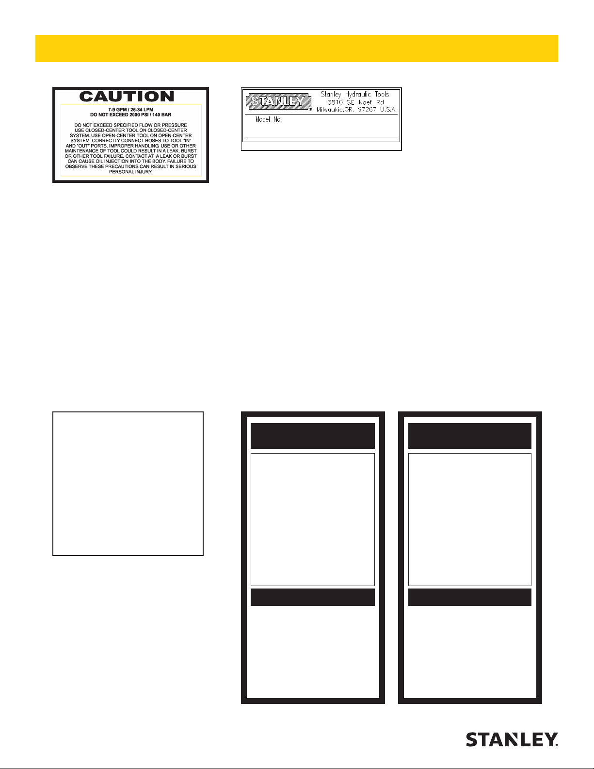
03786
GPM Sticker
TOOL STICKERS & TAGS
02754
SK58 Name Tag
NOTE:
THE INFORMATION LISTED
ON THE STICKERS SHOWN,
MUST BE LEGIBLE AT ALL
TIMES.
REPLACE DECALS IF
THEY BECOME WORN OR
DAMAGED. REPLACEMENTS
ARE AVAILABLE FROM
YOUR LOCAL STANLEY
DISTRIBUTOR.
The safety tag (P/N 15875) at right is
attached to the tool when shipped from
the factory. Read and understand the
safety instructions listed on this tag before
removal. We suggest you retain this tag and
attach it to the tool when not in use.
1. FAILURE TO USE HYDRAULIC HOSE LABELED AND CERTIFIED AS NON-CONDUCTIVE WHEN USING HYDRAULIC
TOOLS ON OR NEAR ELECTRICAL LINES MAY RESULT IN
DEATH OR SERIOUS INJURY.
BEFORE USING HOSE LABELED AND CERTIFIED AS NON-
CONDUCTIVE ON OR NEAR ELECTRIC LINES BE SURE THE
HOSE IS MAINTAINED AS NON-CONDUCTIVE. THE HOSE
SHOULD BE REGULARLY TESTED FOR ELECTRIC CURRENT LEAKAGE IN ACCORDANCE WITH YOUR SAFETY
DEPARTMENT INSTRUCTIONS.
2. A HYDRAULIC LEAK OR BURST MAY CAUSE OIL INJECTION INTO THE BODY OR CAUSE OTHER SEVERE
PERSONAL INJURY.
A. DO NOT EXCEED SPECIFIED FLOW AND PRESSURE
FOR THIS TOOL. EXCESS FLOW OR PRESSURE MAY
CAUSE A LEAK OR BURST.
B. DO NOT EXCEED RATED WORKING PRESSURE OF
HYDRAULIC HOSE USED WITH THIS TOOL. EXCESS
PRESSURE MAY CAUSE A LEAK OR BURST.
C. CHECK TOOL HOSE COUPLERS AND CONNECTORS
DAILY FOR LEAKS. DO NOT FEEL FOR LEAKS WITH
YOUR HANDS. CONTACT WITH A LEAK MAY RESULT
IN SEVERE PERSONAL INJURY.
IMPORTANT
READ OPERATION MANUAL AND
SAFETY INSTRUCTIONS FOR THIS
TOOL BEFORE USING IT.
USE ONLY PARTS AND REPAIR
PROCEDURES APPROVED BY
STANLEY AND DESCRIBED IN THE
OPERATION MANUAL.
TAG TO BE REMOVED ONLY BY
TOOL OPERATOR.
SEE OTHER SIDE
DANGERDANGER
D. DO NOT LIFT OR CARRY TOOL BY THE HOSES. DO
NOT ABUSE HOSE. DO NOT USE KINKED, TORN OR
DAMAGED HOSE.
3. MAKE SURE HYDRAULIC HOSES ARE PROPERLY CONNECTED TO THE TOOL BEFORE PRESSURING SYSTEM.
SYSTEM PRESSURE HOSE MUST ALWAYS BE CONNECTED TO TOOL “IN” PORT. SYSTEM RETURN HOSE
MUST ALWAYS BE CONNECTED TO TOOL “OUT” PORT.
REVERSING CONNECTIONS MAY CAUSE REVERSE
TOOL OPERATION WHICH CAN RESULT IN SEVERE
PERSONAL INJURY.
4. DO NOT CONNECT OPEN-CENTER TOOLS TO CLOSEDCENTER HYDRAULIC SYSTEMS. THIS MAY RESULT IN
LOSS OF OTHER HYDRAULIC FUNCTIONS POWERED BY
THE SAME SYSTEM AND/OR SEVERE PERSONAL INJURY.
5. BYSTANDERS MAY BE INJURED IN YOUR WORK AREA.
KEEP BYSTANDERS CLEAR OF YOUR WORK AREA.
6. WEAR HEARING, EYE, FOOT, HAND AND HEAD PROTECTION.
7. TO AVOID PERSONAL INJURY OR EQUIPMENT DAMAGE,
ALL TOOL REPAIR MAINTENANCE AND SERVICE MUST
ONLY BE PERFORMED BY AUTHORIZED AND PROPERLY
TRAINED PERSONNEL.
IMPORTANT
READ OPERATION MANUAL AND
SAFETY INSTRUCTIONS FOR THIS
TOOL BEFORE USING IT.
USE ONLY PARTS AND REPAIR
PROCEDURES APPROVED BY
STANLEY AND DESCRIBED IN THE
OPERATION MANUAL.
TAG TO BE REMOVED ONLY BY
TOOL OPERATOR.
SEE OTHER SIDE
6 ► SK58 User Manual
SAFETY TAG P/N 15875 (Shown smaller then actual size)
Page 7

HOSE TYPES
The rated working pressure of the hydraulic hose must be equal to or higher than the relief valve setting on the hydraulic system. There are three types of hydraulic hose that meet this requirement and are authorized for use with
Stanley Hydraulic Tools. They are:
Certied non-conductive — constructed of thermoplastic or synthetic rubber inner tube, synthetic ber braid
reinforcement, and weather resistant thermoplastic or synthetic rubber cover. Hose labeled certied non-
conductive is the only hose authorized for use near electrical conductors.
Wire-braided (conductive) — constructed of synthetic rubber inner tube, single or double wire braid reinforcement, and weather resistant synthetic rubber cover. This hose is conductive and must never be used near
electrical conductors.
Fabric-braided (not certied or labeled non-conductive) — constructed of thermoplastic or synthetic rubber inner tube, synthetic ber braid reinforcement, and weather resistant thermoplastic or synthetic rubber cover. This
hose is not certied non-conductive and must never be used near electrical conductors.
HOSE SAFETY TAGS
To help ensure your safety, the following DANGER tags are attached to all hose purchased from Stanley Hydraulic
Tools. DO NOT REMOVE THESE TAGS.
If the information on a tag is illegible because of wear or damage, replace the tag immediately. A new tag may be
obtained from your Stanley Distributor.
THE TAG SHOWN BELOW IS ATTACHED TO “CERTIFIED NON-CONDUCTIVE” HOSE
DANGER
1. FAILURE TO USE HYDRAULIC HOSE LABELED AND CERTIFIED AS NON-CONDUCTIVE
WHEN USING HYDRAULIC TOOLS ON OR NEAR ELECTRIC LINES MAY RESULT IN
DEATH OR SERIOUS INJURY.
FOR PROPER AND SAFE OPERATION MAKE SURE THAT YOU HAVE BEEN PROPERLY TRAINED IN CORRECT PROCEDURES REQUIRED FOR WORK ON OR AROUND
ELECTRIC LINES.
2. BEFORE USING HYDRAULIC HOSE LABELED AND CERTIFIED AS NON-CONDUCTIVE
ON OR NEAR ELECTRIC LINES. WIPE THE ENTIRE LENGTH OF THE HOSE AND FITTING WITH A CLEAN DRY ABSORBENT CLOTH TO REMOVE DIRT AND MOISTURE AND
TEST HOSE FOR MAXIMUM ALLOWABLE CURRENT LEAKAGE IN ACCORDANCE WITH
SAFETY DEPARTMENT INSTRUCTIONS.
DO NOT REMOVE THIS TAG
SEE OTHER SIDE
SIDE 1
3. DO NOT EXCEED HOSE WORKING PRESSURE OR ABUSE HOSE. IMPROPER USE
OR HANDLING OF HOSE COULD RESULT IN BURST OR OTHER HOSE FAILURE.
KEEP HOSE AS FAR AWAY AS POSSIBLE FROM BODY AND DO NOT PERMIT DIRECT
CONTACT DURING USE. CONTACT AT THE BURST CAN CAUSE BODILY INJECTION
AND SEVERE PERSONAL INJURY.
4. HANDLE AND ROUTE HOSE CAREFULLY TO AVOID KINKING, ABRASION, CUTTING, OR
CONTACT WITH HIGH TEMPERATURE SURFACES. DO NOT USE IF KINKED. DO NOT
USE HOSE TO PULL OR LIFT TOOLS, POWER UNITS, ETC.
5. CHECK ENTIRE HOSE FOR CUTS CRACKS LEAKS ABRASIONS, BULGES, OR DAMAGE TO COUPLINGS IF ANY OF THESE CONDITIONS EXIST, REPLACE THE HOSE
IMMEDIATELY. NEVER USE TAPE OR ANY DEVICE TO ATTEMPT TO MEND THE HOSE.
6. AFTER EACH USE STORE IN A CLEAN DRY AREA.
(Shown smaller than actual size)
DANGER
DANGER
SEE OTHER SIDE
SIDE 2
THE TAG SHOWN BELOW IS ATTACHED TO “CONDUCTIVE” HOSE.
DANGER
DANGER
1. DO NOT USE THIS HYDRAULIC HOSE ON OR NEAR ELECTRIC LINES. THIS HOSE IS
NOT LABELED OR CERTIFIED AS NON-CONDUCTIVE. USING THIS HOSE ON OR NEAR
ELECTRICAL LINES MAY RESULT IN DEATH OR SERIOUS INJURY.
2. FOR PROPER AND SAFE OPERATION MAKE SURE THAT YOU HAVE BEEN PROPERLY
TRAINED IN CORRECT PROCEDURES REQUIRED FOR WORK ON OR AROUND ELECTRIC LINES.
3. DO NOT EXCEED HOSE WORKING PRESSURE OR ABUSE HOSE. IMPROPER USE OR
HANDLING OF HOSE COULD RESULT IN BURST OR OTHER HOSE FAILURE. KEEP HOSE
AS FAR AWAY AS POSSIBLE FROM BODY AND DO NOT PERMIT DIRECT CONTACT
DURING USE. CONTACT AT THE BURST CAN CAUSE BODILY INJECTION AND SEVERE
PERSONAL INJURY.
4. HANDLE AND ROUTE HOSE CAREFULLY TO AVOID KINKING, CUTTING, OR CONTACT
WITH HIGH TEMPERATURE SURFACES. DO NOT USE IF KINKED. DO NOT USE HOSE TO
PULL OR LIFT TOOLS, POWER UNITS, ETC.
DO NOT REMOVE THIS TAG
SEE OTHER SIDE
SIDE 1
5. CHECK ENTIRE HOSE FOR CUTS CRACKS LEAKS ABRASIONS, BULGES, OR DAMAGE TO
COUPLINGS IF ANY OF THESE CONDITIONS EXIST, REPLACE THE HOSE IMMEDIATELY.
NEVER USE TAPE OR ANY DEVICE TO ATTEMPT TO MEND THE HOSE.
6. AFTER EACH USE STORE IN A CLEAN DRY AREA.
(Shown smaller than actual size)
DANGER
SEE OTHER SIDE
SIDE 2
DO NOT REMOVE THIS TAG
DO NOT REMOVE THIS TAG
SK58 User Manual ◄ 7
Page 8

Min. Working Pressure
USE
(Press/Return)
HOSE RECOMMENDATIONS
Certied Non-Conductive Hose - Fiber Braid - for Utility Bucket Trucks
Oil Flow Hose Lengths Inside Diameter
GPM LPM FEET METERS INCH MM PSI BAR
4-9 15-34 up to 10 up to 3 3/8 10 Both 2250 155
Conductive Hose - Wire Braid or Fiber Braid -DO NOT USE NEAR ELECTRICAL CONDUCTORS
4-6 15-23 up to 25 up to 7.5 3/8 10 Both 2500 175
4-6 15-23 26-100 7.5-30 1/2 13 Both 2500 175
5-10.5 19-40 up to 50 up to 15 1/2 13 Both 2500 175
5-10.5 19-40 51-100 15-30 5/8 16 Both 2500 175
5/8 16 Pressure 2500 175
3/4 19 Return 2500 175
5-10.5 19-40 100-300 30-90
10-13 38-49 up to 50 up to 15 5/8 16 Both 2500 175
5/8 16 Pressure 2500 175
3/4 19 Return 2500 175
10-13 38-49 51-100 15-30
3/4 19 Pressure 2500 175
1 25.4 Return 2500 175
10-13 38-49 100-200 30-60
5/8 16 Pressure 2500 175
3/4 19 Return 2500 175
13-16 49-60 up to 25 up to 8
3/4 19 Pressure 2500 175
1 25.4 Return 2500 175
13-16 49-60 26-100 8-30
PRESSURE
<<< FLOW
RETURN
FLOW >>>
Figure 1. Typical Hose Connections
Tool to Hydraulic Circuit Hose
Recommendations
The chart to the right shows recommended
minimum hose diameters for various hose
lengths based on gallons per minute (gpm)/
liters per minute (lpm). These recommenda-
tions are intended to keep return line pressure
(back pressure) to a minimum acceptable lev-
el to ensure maximum tool performance.
8 ► SK58 User Manual
This chart is intended to be used for hydraulic
tool applications only based on Stanley Hy-
draulic Tools tool operating requirements and
should not be used for any other applications.
All hydraulic hose must have at least a rated
minimum working pressure equal to the maxi-
mum hydraulic system relief valve setting.
All hydraulic hose must meet or exceed
specications as set forth by SAE J517.
Page 9

HTMA / EHTMA REQUIREMENTS
HTMA / EHTMA REQUIREMENTS
HTMA
HYDRAULIC SYSTEM REQUIREMENTS
Flow Range
Nominal Operating Pressure
(at the power supply outlet)
System relief valve setting
(at the power supply outlet)
Maximum back pressure
(at tool end of the return hose)
Measured at a max. uid viscosity of:
(at min. operating temperature)
Temperature: Sufcient heat rejection
capacity to limit max. uid temperature to:
(at max. expected ambient temperature)
Min. cooling capacity at a temperature
difference of between ambient and uid
temps
NOTE:
Do not operate the tool at oil temperatures above 140° F (60° C). Operation at higher temperatures can cause operator
discomfort at the tool.
Filter
Min. full-ow ltration
Sized for ow of at least:
(For cold temp. startup and max.
dirt-holding capacity)
4-6 gpm 7-9 gpm 9-10.5 gpm 11-13 gpm
(15-23 lpm) (26-34 lpm) (34-40 lpm) (42-49 lpm)
1500 psi 1500 psi 1500 psi 1500 psi
(103 bar) (103 bar) (103 bar) (103 bar)
2100-2250 psi 2100-2250 psi 2200-2300 psi 2100-2250 psi
(145-155 bar) (145-155 bar) (152-159 bar) (145-155 bar)
250 psi 250 psi 250 psi 250 psi
(17 bar) (17 bar) (17 bar) (17 bar)
400 ssu* 400 ssu* 400 ssu* 400 ssu*
(82 centistokes) (82 centistokes) (82 centistokes) (82 centistokes)
140° F 140° F 140° F 140° F
(60° C) (60° C) (60° C) (60° C)
3 hp 5 hp 6 hp 7 hp
(2.24 kW) (3.73 kW) (5.22 kW) (4.47 kW)
40° F 40° F 40° F 40° F
(22° C) (22° C) (22° C) (22° C)
25 microns 25 microns 25 microns 25 microns
30 gpm 30 gpm 30 gpm 30 gpm
(114 lpm) (114 lpm) (114 lpm) (114 lpm)
TYPE I TYPE II
TOOL TYPE
TYPE RR
TYPE III
Hydraulic uid Petroleum based
(premium grade, anti-wear, non-conductive)
Viscosity (at min. and max. operating temps)
NOTE:
When choosing hydraulic uid, the expected oil temperature extremes that will be experienced in service determine the
most suitable temperature viscosity characteristics. Hydraulic uids with a viscosity index over 140 will meet the requirements
over a wide range of operating temperatures.
*SSU = Saybolt Seconds Universal
EHTMA
100-400 ssu* 100-400 ssu* 100-400 ssu* 100-400 ssu*
(20-82 centistokes)
CLASSIFICATION
HYDRAULIC SYSTEM
REQUIREMENTS
Flow Range
Nominal Operating Pressure
(at the power supply outlet)
System relief valve setting
(at the power supply outlet)
NOTE: These are general hydraulic system requirements. See tool specication page for tool specic requirements
B
3.5-4.3 gpm 4.7-5.8 gpm 7.1-8.7 gpm 9.5-11.6 gpm 11.8-14.5 gpm
(13.5-16.5 lpm) (18-22 lpm) (27-33 lpm) (36-44 lpm) (45-55 lpm)
1870 psi 1500 psi 1500 psi 1500 psi 1500 psi
(129 bar) (103 bar) (103 bar) (103 bar) (103 bar)
2495 psi 2000 psi 2000 psi 2000 psi 2000 psi
(172 bar) (138 bar) (138 bar) (138 bar) (138 bar)
C
D
SK58 User Manual ◄ 9
Page 10

NOTICE
OPERATION
The recommended hose size is .500 inch/12 mm I.D. up
to 50 ft/15 m long and .625 inch/16 mm I.D. minimum up
to 100 ft/30 m.
PRE-OPERATION PROCEDURES
CHECK POWER SOURCE
1. Using a calibrated owmeter and pressure gauge,
check that the hydraulic power source develops a
ow of 7-9 gpm/26-34 lpm at 1500-2000 psi/105-
140 bar.
2. Make certain the hydraulic power source is equipped
with a relief valve set to open at 2100-2250 psi/145155 bar maximum.
INSTALL DRILL STEEL & ROCK BIT
Use standard 4-1/4 inch shank × 1 inch hex drill steel
for SK58110, SK58120 and SK58310 models and 4-1/4
inch shank × 7/8 inch hex drill steel for the SK58130
model.
Drill steels are available in a variety of lengths. Start
with a short length so that the tool may be operated at a
normal standing position. The tool handles should never
exceed chest height during operation.
1. Thread a rock bit onto the drill steel.
2. Rotate the latch (61) out and up.
3. Slide the drill steel into the tool.
4. Rotate the latch down being careful not to pinch your
ngers. When correctly installed, the collar on the
drill steel should be above the bottom of the latch.
CONNECT HOSES
1. Wipe all hose couplers with a clean, lint-free cloth
before making connections.
2. Connect the hoses from the hydraulic power source
to the tool ttings or quick disconnects. It is a good
practice to connect return hoses rst and discon-
nect them last to minimize or avoid trapped pressure
within the tool.
3. Observe ow indicators stamped on hose couplers
to ensure that uid ow is in the proper direction.
The female coupler on the tool hose is the inlet coupler.
4. Move the hydraulic circuit control valve to the ON
position to operate the tool.
NOTE:
If uncoupled hoses are left in the sun, pressure in-
crease within the hoses may make them difcult to
connect. When possible, connect the free ends of
the hoses together.
5. Connect the hose from the air supply to the hose on
the tool.
The air supply must be minimum 30 cfm at 120
psi. Supplying less than these specications may
result in inadequate extraction of rock cuttings;
cause cuttings to migrate up the drill steel and
into the tool and result in tool damage; diminish
drilling time; and cause premature wear of the
drill bit.
OPERATION PROCEDURES
1. Observe all safety precautions.
2. Install the appropriate tool bit for the job.
3. Start the hydraulic supply and turn the circuit control
valve to the ON position.
4. Open the air valve on the tool just enough to permit
a small amount of air ow from the tool bit.
NOTE:
Air ow must be continuous during drilling to avoid
clogging of the air passages and/or back-ushing of
waste products into the drill.
5. Place the bit rmly on the surface to be drilled.
6. Open the hydraulic valve lever slightly to start the
tool at a slow speed. Adequate down pressure is
very important.
7. Ensure the rock bit is rotating at a moderate speed
(not too fast, not too slow). When starting the hole,
it is best to start at a slow impact and rotation speed
until the rock bit has carved out a depression in the
material being drilled. If the rock bit is not rotating
open the hydraulic valve lever further. If the rock bit
still does not rotate adjust the motor control knob
until rotation is achieved.
10 ► SK58 User Manual
Page 11

OPERATION
8. After the rock bit has carved out a depression in the
material being drilled, open the hydraulic valve lever fully. Readjust the motor control knob to obtain
a good drilling speed. Adjust the air valve to ensure
the cuttings are being extracted from the drill hole.
9. When the bottom of the tool comes within 6 inches
of the drill hole, it is time to either add another section of drill steel or replace the existing drill steel with
a longer section. Close the hydraulic valve lever but
leave the air valve “ON” and then lift the tool with
drill steel and rock bit out of the hole. Leaving the
air valve “ON” helps prevent cuttings from falling
around the bit while the bit is lifted from the hole.
10. When the tool, drill steel and bit have been removed
from the drill hole, turn the valve lever “OFF” and
turn the hydraulic supply circuit control valve “OFF”
before changing the drill steel or rock bit.
COLD WEATHER OPERATION
If the breaker is to be used during cold weather, preheat
the hydraulic uid at low engine speed. When using the
normally recommended uid, uid temperature should
be at or above 50 °F/10 °C (400 ssu/82 centistokes) before use.
Damage to the hydraulic system or breaker can result
from use with uid that is too viscous or thick.
SK58 User Manual ◄ 11
Page 12

NOTICE
TOOL PROTECTION & CARE
In addition to the Safety Precautions found in
this manual, observe the following for equipment
protection and care.
• Make sure all couplers are wiped clean before connection.
• The hydraulic circuit control valve must be in the
“OFF” position when coupling or uncoupling hydraulic tools. Failure to do so may result in damage to
the quick couples and cause overheating of the hydraulic system.
• Always store the tool in a clean dry space, safe from
damage or pilferage.
• Make sure the circuit PRESSURE hose (with male
quick disconnect) is connected to the “IN” port. The
circuit RETURN hose (with female quick disconnect)
is connected to the opposite port. Do not reverse cir-
cuit ow. This can cause damage to internal seals.
• Always replace hoses, couplings and other parts
with replacement parts recommended by Stanley
Hydraulic Tools. Supply hoses must have a minimum working pressure rating of 2500 psi/172 bar.
• Do not exceed the rated ow (see Specications in
this manual for correct ow rate and model number).
Rapid failure of the internal seals may result.
• Always keep critical tool markings, such as warning
stickers and tags legible.
• Keep tool bit sharp for maximum drilling performance. Make sure that tool bits are not chipped or
rounded on the striking end.
• Never operate a hammer drill without a tool bit or
without holding it against the work surface.
• Tool repair should be performed by experienced
personnel only.
• Make certain that the recommended relief valves
are installed in the pressure side of the system.
• Do not use the tool for applications for which it was
not intended.
12 ► SK58 User Manual
Page 13

TROUBLESHOOTING
PROBLEM CAUSE REMEDY
Tool does not run. Power unit not functioning. Check power unit for proper ow and pressure
(7–9 gpm/26–34 lpm, 1500–2000 psi/105–140 bar.
Couplers or hoses blocked. Remove restriction.
Pressure and return line hoses
reversed at ports.
Mechanical failure of piston or
automatic valve.
Tool does not drill effectively. Power unit not functioning. Check power unit for proper ow and pressure
Couplers or hoses blocked. Remove restriction.
Low accumulator charge (pressure
hose will pulse more than normal).
Fluid too hot (above 140.°F/60.°C). Provide cooler to maintain proper uid
Insufcient air or water. 20 cfm minimum.
Tool operates slow. Low gpm supply from power unit. Check power unit for proper ow (7–9 gpm/26–34
High back-pressure. Check hydraulic system for excessive back-
Couplers or hoses blocked. Remove restriction.
Orice plug blocked. Remove restriction.
Fluid too hot (above 140 °F/60 °C)
or too cold (below 60 °F/16 °C).
Relief valve set too low. Adjust relief valve to 2100–2250 psi/145–155 bar.
Tool gets hot. Hot uid going through tool. Check power unit. Be sure ow rate is not too
Fluid leakage on drill steel. Lower piston or drive hex seal
failure.
Fluid leakage through charge
valve cap.
Fluid leakage around trigger. Valve spool seal failure. Replace seals.
Low rotation torque. Motor not completely broken in. Continue operation to break in motor.
Upper piston seal failure or
accumulator O-ring failure or
accumulator charge loss or failure.
Excessive oil temperature causes
operating pressure loss.
Damage to motor clearances. Repair as required.
Insufcient air or water. 20 cfm minimum.
Mechanical binding during drilling. Take care to guide drill straight.
Be sure hoses are connected to their proper ports.
Disassemble breaker and inspect for damaged
parts.
(7-9 gpm/26-34 lpm, 1500-2000 psi/105-140 bar.
Recharge accumulator. Replace diaphragm if
charge loss continues.
temperature (130 °F/55 °C).
lpm).
pressure (over 250 psi/17 bar).
Check power unit for proper uid temperature.
Bypass cooler to warm the uid or provide cooler
to maintain proper temperature.
high causing part of the uid to go through the
relief valve. Provide cooler to maintain proper uid
temperature (140 °F/60 °C max).
Check the relief valve setting.
Replace seals.
Replace seals, recharge or replace accumulator
diaphragm.
Provide cooler to maintain oil temperature (under
140 °F).
SK58 User Manual ◄ 13
Page 14

CHARGING THE ACCUMULATOR
ACCUMULATOR TESTING
PROCEDURE
To check or charge the accumulator the following equipment is required:
31254 Charge Kit: which includes the following: (Shown
in Figure 2 on the next page.)
• Accumulator Tester (Part Number 02835).
• Charging Assembly (P/N 15304) Includes a liquid
lled gauge w/snub valve, hose and charge tting.
• NITROGEN bottle with a 800 psi/56 bar minimum
charge. (Not included in 31254 Charge Kit.)
1. Remove the valve cap assembly from the sinker
drill.
2. Remove the protective cap and loosen the 5/8-inch
hex locking nut on the tool charging valve 1-1/2
turns.
3. Holding the chuck end of Accumulator Tester (P/N
02835) turn the gauge fully counterclockwise to ensure that the stem inside the chuck is completely
retracted.
4. Thread the tester onto the accumulator charging valve. Do not advance the gauge-end into the
chuck-end. Turn as a unit. Seat the chuck on the
accumulator charging valve and hand tighten only.
5. Advance the valve stem of the tester by turning the
gauge-end clockwise until a pressure is read on the
gauge (charge pressure should be 600-700 psi/4248 bar).
6. If pressure is OK unscrew the gauge-end from the
chuck to retract the stem, then unscrew the entire
tester assembly from the accumulator charging
valve. If pressure is low, charge the accumulator as
described in the following procedure.
7. Tighten the 5/8-inch hex locking nut on the tool
charging valve. Be careful not to overtighten. Install
the protective cap and valve cap assembly.
ACCUMULATOR CHARGING
1. Perform steps 1 through 4 of the accumulator testing procedure above.
2. Connect the chuck of the charging assembly to the
charging valve on the accumulator tester or, if preferred, remove the tester from the charging valve
and connect the charging assembly chuck directly
to the charging valve.
3. Adjust the regulator to the charging pressure of 600
psi/42 bar.
NOTE:
It may be necessary to set the gauge at 650-700
psi/45-48 bar to overcome any pressure drop
through the charging system.
4. Open the valve on the charging assembly hose.
5. When the accumulator is fully charged close the
valve on the charging assembly hose and remove
the charging assembly chuck from the accumulator
tester or tool charging valve.
6. If the accumulator tester has been used, be sure to
turn the gauge-end fully counterclockwise before removing the tester from the charging valve of the tool.
7. Tighten the 5/8-inch hex locking nut on the tool
charging valve and replace the protective cap.
8. Replace the valve cap assembly.
GENERAL SERVICE NOTES
1. If the breaker is repainted after servicing, be sure to
mask off the vent in the valve cap assembly. Do not
allow paint to enter the IN and OUT ports or the bore
of the foot assembly.
2. If the handle grips need to be replaced.
a. Remove the old grips and clean the handle.
b. Wash the new grips and the handle clean and
dry, simply push or drive the grips on. DO NOT
lubricate the parts. The grips will not be secure
on the handle if any grease or oil is used.
14 ► SK58 User Manual
Page 15

CHARGING THE ACCUMULATOR
Figure 2. Charging the Accumulator
SK58 User Manual ◄ 15
Page 16

SPECIFICATIONS
Shank Size (SK58110 Air, SK58120 Water, SK58310 UW Air) ....................................................4-1/4 in. × 1 in. Hex
Shank Size (SK58130 Air) .........................................................................................................4-1/4 in. × 7/8 in. Hex
Pressure Range.............................................................................................................. 1500–2000 psi/105–140 bar
Flow Range .................................................................................................................................7-9 gpm / 26-34 lpm
Optimum Flow ..................................................................................................................................... 8 gpm / 30 lpm
Maximum Back Pressure...................................................................................................................... 250 psi/17 bar
Connect Size & Type ...........................................................................................................3/8 in. Male Pipe Adapter
Weight ....................................................................................................................................................67 lbs / 30 kg
Length.................................................................................................................................................... 26 in. / 66 cm
Width ..................................................................................................................................................... 18 in. / 46 cm
Hose Whips ................................................................................................................................................... Included
Port Size ................................................................................................................................................-8 SAE O-ring
Air Supply ........................................................................................................................ Minimum 30 cfm @ 120 psi
VIBRATION DECLARATION
SK58310 MODELS
DECLARED VIBRATION EMISSION VALUE IN ACCORDANCE WITH ISO-28927-10 2011, EN 12096
MEASURED VIBRATION EMISSION VALUE: 3-AXIS ....................................................................... 17.7 M/SEC²
UNCERTAINTY: K ................................................................................................................................. 1.4 M/SEC²
MEASURED VIBRATION EMISSION VALUE WITH UNCERTAINTY: 3-AXIS ................................... 19.1 M/SEC²
MEASURED VIBRATION EMISSION VALUE: Z-AXIS ....................................................................... 16.0 M/SEC²
UNCERTAINTY: K ................................................................................................................................. 1.2 M/SEC²
MEASURED VIBRATION EMISSION VALUE WITH UNCERTAINTY: Z-AXIS ................................... 17.2 M/SEC²
ACCESSORIES
DRILL STEELS FOR USE WITH AIR
1 in. Hex × 4-1/4 in. H Thread, 24 in. / 61 cm UC .............................................................................................. 05170
1 in. Hex × 4-1/4 in. H Thread, 36 in. / 91 cm UC .............................................................................................. 04915
1 in. Hex × 4-1/4 in. H Thread, 48 in. / 122 cm UC ............................................................................................ 05171
7/8 in. Hex × 4-1/4 in. H Thread, 24 in. / 61 cm UC ........................................................................................... 05174
CARBIDE ROCK BITS FOR USE WITH AIR (SHOULDER DESIGN)
1-3/8 in. Diameter H Thread .............................................................................................................................. 05177
1-1/2 in. Diameter H Thread .............................................................................................................................. 05178
UC denotes dimension measured from bottom tip of tool to bottom surface of collar.
SERVICE TOOLS
O-ring Tool Kit .................................................................................................................................................... 04337
Accumulator Disassembly Tool .......................................................................................................................... 05508
Accumulator Cylinder Puller ..............................................................................................................................05640
Split Rings .........................................................................................................................................................04908
Flow Sleeve Removal Tube ...............................................................................................................................04910
Bearing Installation Tool .................................................................................................................................... 05044
Bearing Installation Tool .................................................................................................................................... 05061
Latch Removal Tool ........................................................................................................................................... 05045
Latch Installation Tool ........................................................................................................................................ 05879
Collet, 7/8 in.......................................................................................................................................................05871
Latch Installation Tool ........................................................................................................................................ 05062
16 ► SK58 User Manual
Page 17

SK58 PARTS ILLUSTRATION
SK58 User Manual ◄ 17
Page 18

SK58 PARTS LIST
PART
ITEM
NO. QTY DESCRIPTION
1 04763 1 AIR TUBE
04965 1 WATER TUBE (SK58120 ONLY)
2 07064 1 VENT PLUG
3 04964 2 HANDLE GRIP ASSEMBLY
4 01714 1 NUT HEAVY HEX JAM
5 04786 2 WASHER
6 04794 1 O-RING *
7 04147 1 LOCKNUT
8 04718 1 VALVE LEVER
9 04902 1 RETAINING RING
10 04751 1 WASHER
11 04793 1 KAP SEAL *
12 04775 1 CHARGE VALVE CAP
13 04052 1 O-RING *
14 04051 1 CHARGING VALVE
15 — 1 O-RING (INCLUDED W/ ITEM 14)
17 00955 1 PIPE PLUG
18 01411 1 O-RING *
19 04772 1 ORIFICE PLUG
20 01605 2 O-RING *
21 04054 3 O-RING *
22 04060 1 ACCUMULATOR CYLINDER
23 04059 1 ACCUMULATOR DIAPHRAGM
24 04779 1 ACCUMULATOR CHAMBER
25 04780 1 BACK UP WASHER
26 04386 1 CUP SEAL *
27 04750 1 WASHER
28 06268 1 TUBE SEAL
29 04734 1 PISTON (SK58110 / SK58130)
06265 1 PISTON (SK58120 / SK58310)
30 04068 1 FLOW SLEEVE TUBE
31 07889 1 FLOW SLEEVE
32 04065 1 AUTOMATIC VALVE
33 07890 1 ROLL PIN
34 01652 2 PIGTAIL HOSE ASSEMBLY
35 04781 1 INLET FLANGE
36 02688 2 CAPSCREW
37 04792 1 KAP SEAL *
38 02003 1 O-RING*
39 04771 1 WASHER
40 04791 1 KAP SEAL *
41 04795 1 O-RING *
42 04777 1 THROTTLE VALVE
(SK58110/SK58130/SK58310 ONLY)
(SK58120/SK58130 ONLY) *
PART
ITEM
NO. QTY DESCRIPTION
43 04778 1 BLOWER TUBE NUT
44 00016 1 O-RING *
45 00175 1 O-RING *
46 04660 1 HOUSING
47 00772 1 KEY
48 07291 1 MODIFIED CAPSCREW
49 04512 1 RETAINING RING
50 04764 1 SWIVEL FITTING
51 00106 1 O-RING *
52 04765 1 INLET SWIVEL BODY
53 04767 1 STREET ELBOW 45°
54 05202 1 VALVE-AIR ONLY
55 04801 1 HOSE ASSEMBLY
56 04066 1 AUTOMATIC VALVE BODY
57 04571 2 PUSH PIN
58 04067 4 PUSH PIN
59 03786 1 GPM STICKER
60 05152 1 STANLEY STICKER
61 04721 1 LATCH CASTING
62 04761 1 RETAINING RING
63 04759 1 SPRING BACK-UP
64 04758 1 COIL SPRING
65 04756 1 LATCH WASHER
66 04075 4 SIDE ROD NUT
67 01217 2 CAPSCREW
68 04748 1 MOTOR PLATE
69 00783 1 PIPEPLUG
70 04788 2 DU BEARING
71 03826 2 DU BEARING
72 04033 1 IDLER GEAR
73 01277 1 O-RING *
74 00713 2 DOWEL PIN
75 04744 1 DRIVE MOTOR CHAMBER
76 04784 1 DRIVE HEX (SK58110 ONLY)
06267 1 DRIVE HEX (SK58120/SK58310 ONLY)
05195 1 DRIVE HEX (SK58130 ONLY)
77 04787 1 WOODDRUFF KEY
78 04373 4 SIDE ROD
79 04774 1 GASKET *
80 23395 2 QUAD RING *
81 23399 2 BACK-UP RING *
82 04769 1 DRIVE MOTOR CONTROL BLOCK
06266 1 DRIVE MOTOR CONTROL BLOCK
(SK58110/SK58130/SK58310 ONLY)
(SK58110/SK58130/SK58310 ONLY)
(SK58120 ONLY)
18 ► SK58 User Manual
Page 19

SK58 PARTS LIST
PART
ITEM
NO. QTY DESCRIPTION
83 00634 2 NYLON CAP LOCK
84 01362 1 O-RING *
85 01605 1 O-RING *
86 18643 1 SETSCREW
87 04753 1 MOTOR CONTROL KNOB
88 04773 1 VALVE GUIDE
89 04783 1 MOTOR CONTROL VALVE
90 04073 1 O-RING *
91 30890 1 ROD SEAL *
92 04755 1 SEAL WASHER
93 04790 1 CUP SEAL *
94 03009 1 ROLL PIN
95 02688 1 HSHCS
96 03047 2 ROLL PIN
97 04754 1 THRUST BACK-UP WASHER
98 04789 1 THRUST WASHER
99 04752 1 DRIVE GEAR
100 05641 1 O-RING *
101 00026 2 O-RING *
102 04776 1 TUBE CONNECTOR
103 02754 1 NAME TAG
104 04768 1 WATER VALVE (SK58120 ONLY)
04805 SEAL KIT
SK58110 – 1 INCH × 4-1/4 HEX SHANK AIR
SK58120 – 1 INCH × 4-1/4 HEX SHANK WATER
SK58130 – 7/8 INCH × 4-1/4 HEX SHANK AIR
SK58310 – 1 INCH × 4-1/4 HEX SHANK AIR, UNDERWATER USE
NOTE:
USE PART NUMBER AND PART NAME WHEN ORDERING.
* DENOTES PART OF SEAL KIT P/N 04805
SK58 User Manual ◄ 19
Page 20

UNDERWATER TOOLS DEPTH GUIDELINE
UNDERWATER MODELS ONLY
CAUTION
DO NOT USE HYDRAULIC TOOLS UNDER-
WATER THAT ARE NOT DESIGNATED AS
AN “UNDERWATER” MODEL, OR THIS
WILL RESULT IN DAMAGE TO THE TOOL.
For underwater hydraulic tools the applications are
broken down into four quadrants depending on
type of tool and method of operation.
The types of tools are percussive and rotational,
each with different characteristics allowing for different depth operation. With percussive tools, the
nitrogen accumulator PSI must counter the increase in ambient pressure found at lower depths.
Since there is a maximum PSI for percussive tools
they are limited to certain depths. Rotational tools
do not have accumulators and thus capable of
deeper depths.
Operation Overview
Percussive Rotational
Tools: Breakers,
Hammer Drills and
Chipping Hammers
Max Depth: 500' -
DiverROV
limitations due to
accumulator PSI
max (increase 40
PSI for every 100')
Tools: Breakers,
Hammer Drills and
Chipping Hammers
Max Depth: 500' limitations due to
accumulator PSI
max (increase 40
PSI for every 100')
Tools: Grinders,
Saws, Chain Saws
Max Depth: 1000' Reference hose
sizing guide below
Tools: Grinders,
Saws, Chain Saws
Max Depth: 1000' Reference hose
sizing guide below
The methods are broken into diver operated or
remote operated vehicle (ROV). ROV's can reach
lower depths and with an on-board hydraulic
power source that is depth compensated, can
operate hydraulic tools at depths of thousands of
feet. ROV operation is still limited to the tool, for
example a percussive tool has the same depth
limitation whether ROV or diver operated.
Recommended Hose Diameters
Depth (ft) 8 GPM 12 GPM
100 5/8” 5/8”
300 3/4” 1”
600 1” 1”
1000 1” 1-1/4”
20 ► SK58 User Manual
Page 21

NOTES
SK58 User Manual ◄ 21
Page 22

Stanley Hydraulic Tools
3810 SE Naef Road
Milwaukie, Oregon 97267-5698 USA
(503) 659-5660 / Fax (503) 652-1780
www.stanleyhydraulics.com
 Loading...