

Page 1
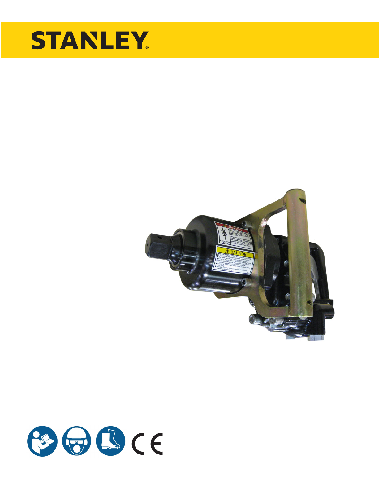
IW16
HYDRAULIC
IMPACT WRENCH
USER MANUAL
Safety, Operation and Maintenance
© 2014 Stanley Black & Decker, Inc.
New Britain, CT 06053
U.S.A.
66174 8/2014 Ver 14
Page 2
DECLARATION OF CONFORMITY
ÜBEREINSTIMMUNGS-ERKLARUNG
DECLARATION DE CONFORMITE CEE
DECLARACION DE CONFORMIDAD
DICHIARAZIONE DI CONFORMITA
Hydraulic Tools
______________________________________________________________________
I, the undersigned:
Ich, der Unterzeichnende:
Je soussigné:
El abajo firmante:
lo sottoscritto:
Weisbeck, Andy
Surname and First names/Familiennname und Vornamen/Nom et prénom /Nombre y apellido/Cognome e nome
hereby declare that the equipment specified hereunder:
bestätige hiermit, daß erklaren Produkt genannten Werk oder Gerät:
déclare que l’équipement visé ci-dessous:
Por la presente declaro que el equipo se especifica a continuación:
Dichiaro che le apparecchiature specificate di seguito:
1. Category:
Hydraulic Hand Held Impact Wrench
Kategorie:
Catégorie:
Categoria:
Categoria:
2. Make/Marke/Marque/Marca/Marca
Stanley
3. Type/Typ/Type/Tipo/Tipo:
IW16150, IW16150S, IW16350
4. Serial number of equipment:
Seriennummer des Geräts:
Numéro de série de l’équipement:
Numero de serie del equipo:
Matricola dell´attrezzatura:
ALL MODELS NOTED ABOVE FROM
SERIAL NUMBER (042312097) and Above
Has been manufactured in conformity with
Wurde hergestellt in Übereinstimmung mit
Est fabriqué conformément
Ha sido fabricado de acuerdo con
E’ stata costruita in conformitá con
Directive/Standards
Richtlinie/Standards
Directives/Normes
Directriz/Los Normas
Direttiva/Norme
No.
Nr
Numéro
No
n.
Approved body
Prüfung durch
Organisme agréé
Aprobado
Collaudato
EN
EN ISO
EN
Machinery Directive
792-6:1994
3744:2009
28927-2:2009
2006/42/EC:2006
Self
Self
Self
Self
5. Special Provisions: None
Spezielle Bestimmungen:
Dispositions particulières:
Provisiones especiales:
Disposizioni speciali:
6. Representative in the Union: Patrick Vervier, Stanley Dubuis 17-19, rue Jules Berthonneau-BP 3406 41034 Blois Cedex, France.
Vertreter in der Union/Représentant dans l’union/Representante en la Union/Rappresentante presso l’Unione
Done at/Ort/Fait à/Dado en/Fatto a Stanley Hydraulic Tools, Milwaukie, Oregon USA
Date/Datum/le/Fecha/Data 12-22-10
Signature/Unterschrift/Signature/Firma/Firma
Position/Position/Fonction/Cargo/Posizione Engineering Manager
DECLARATION OF CONFORMITY
2 ► IW16 User Manual
Page 3

WARNING
IMPORTANT
TABLE OF CONTENTS
DECLARATION OF CONFORMITY .......................................................................................................................... 2
SAFETY SYMBOLS ..................................................................................................................................................4
SAFETY PRECAUTIONS .......................................................................................................................................... 5
TOOL STICKERS & TAGS ........................................................................................................................................6
HOSE TYPES ............................................................................................................................................................7
HOSE RECOMMENDATIONS .................................................................................................................................. 8
FIGURE 1. TYPICAL HOSE CONNECTIONS .......................................................................................................8
HTMA REQUIREMENTS ...........................................................................................................................................9
WRENCH TORQUE INFORMATION ...................................................................................................................... 10
WRENCH OPERATION .......................................................................................................................................... 11
EQUIPMENT PROTECTION & CARE ....................................................................................................................12
TROUBLESHOOTING ............................................................................................................................................13
SPECIFICATIONS ................................................................................................................................................... 14
ACCESSORIES.......................................................................................................................................................15
IW16 PARTS ILLUSTRATION .................................................................................................................................16
IW16 PARTS LIST ................................................................................................................................................... 17
VALVE HANDLE CHANGE NOTICE .......................................................................................................................18
IW16 EXTENSION HANDLE ILLUSTRATION ........................................................................................................ 19
UNDERWATER TOOLS DEPTH GUIDELINE .........................................................................................................20
To ll out a Product Warranty Recording form, and for information on your warranty,
visit Stanleyhydraulics.com and select the Company tab, Warranty.
(NOTE: The warranty recording form must be submitted to validate the warranty).
SERVICING: This manual contains safety, operation, and routine maintenance instructions. Stanley Hydraulic Tools
recommends that servicing of hydraulic tools, other than routine maintenance, must be performed by an authorized
and certied dealer. Please read the following warning.
SERIOUS INJURY OR DEATH COULD RESULT FROM THE IMPROPER REPAIR OR
SERVICE OF THIS TOOL.
REPAIRS AND / OR SERVICE TO THIS TOOL MUST ONLY BE DONE BY AN
AUTHORIZED AND CERTIFIED DEALER.
For the nearest authorized and certied dealer, call Stanley Hydraulic Tools at the number listed on the back of this
manual and ask for a Customer Service Representative.
IW16 User Manual ◄ 3
Page 4
DANGER
WARNING
CAUTION
CAUTION
NOTICE
IMPORTANT
SAFETY SYMBOLS
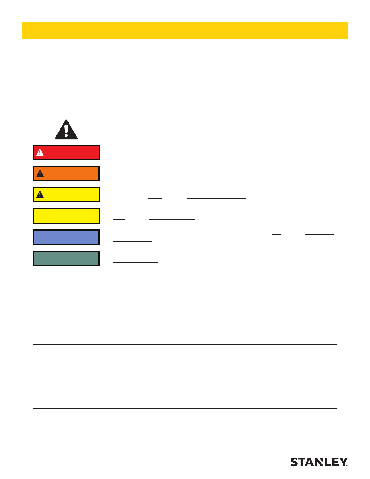
Safety symbols and signal words, as shown below, are used to emphasize all operator, maintenance and repair actions which, if not strictly followed, could result in a life-threatening situation, bodily injury or damage to equipment.
This is the safety alert symbol. It is used to alert you to potential personal injury
hazards. Obey all safety messages that follow this symbol to avoid possible injury
or death.
This safety alert and signal word indicate an imminently hazardous situation which,
if not avoided, will result in death or serious injury.
This safety alert and signal word indicate a potentially hazardous situation which, if
not avoided, could result in death or serious injury.
This safety alert and signal word indicate a potentially hazardous situation which, if
not avoided, could result in death or serious injury.
This signal word indicates a potentially hazardous situation which, if not avoided,
may result in property damage.
This signal word indicates a situation which, if not avoided, will result in damage to
the equipment.
This signal word indicates a situation which, if not avoided, may result in damage
to the equipment.
Always observe safety symbols. They are included for your safety and for the protection of the tool.
LOCAL SAFETY REGULATIONS
Enter any local safety regulations here. Keep these instructions in an area accessible to the operator and maintenance personnel.
4 ► IW16 User Manual
Page 5

SAFETY PRECAUTIONS
Tool operators and maintenance personnel must always
comply with the safety precautions given in this manual
and on the stickers and tags attached to the tool and
hose. These safety precautions are given for your safety. Review them carefully before operating the tool and
before performing general maintenance or repairs.
Supervising personnel should develop additional pre-
cautions relating to the specic work area and local
safety regulations. If so, place the added precautions in
the space provided in this manual.
The model IW16 Hydraulic Impact Wrench will provide
safe and dependable service if operated in accordance
with the instructions given in this manual. Read and understand this manual and any stickers and tags attached
to the tool and hose before operation.
Failure to do so could result in personal injury or equipment damage.
• The operator must start in a work area without by-
standers. Flying debris can cause serious injury.
• Do not operate the tool unless thoroughly trained
or under the supervision of an instructor. Establish
a training program for all operators to ensure safe
operation.
• Always wear safety equipment such as goggles,
gloves, ear, head and breathing protection, and
safety shoes at all times when operating the tool.
Use gloves and aprons when necessary.
• Inspect tool daily for loose fasteners, missing parts
and leakage. Have tool repaired if necessary.
• The operator must be familiar with all prohibited
work areas such as excessive slopes and dangerous terrain conditions.
• Maintain proper footing and balance at all times and
do not overreach.
• Do not inspect or clean the tool while the hydraulic
power source is connected. Accidental engagement
of the tool can cause serious injury. Be observant of
hydraulic and water hose lying about the work area,
they can be a tripping hazard.
• Always connect hoses to the tool hose couplers be-
fore energizing the hydraulic power source. Be sure
all hose connections are tight and are in good condition.
• Do not operate the tool at oil temperatures above
140 °F/60 °C. Operation at higher temperatures can
cause higher than normal temperatures at the tool
which can result in operator discomfort.
• Do not operate a damaged, improperly adjusted, or
incompletely assembled impact wrench.
• Never wear loose clothing that can get entangled in
the working parts of the tool.
• Keep all parts of your body away from the rotating
parts. Long hair or loose clothing can become drawn
into rotating components.
• Always use accessories that conform to the speci-
cations given in the OPERATION section of this
manual.
• Do not reverse impact wrench rotation direction by
changing uid ow direction.
• Release the trigger if the power supply has been interrupted.
• When working near electrical conductors, always
assume that all conductors are energized and that
insulation, clothing and hoses can conduct electricity. Use hose labeled and certied as non-conductive.
• To avoid personal injury or equipment damage, all
tool repair, maintenance and service must only be
performed by authorized and properly trained personnel.
• Serious injury or death could result from a tool or
accessories dropped from an elevated height, also
ying debris can cause serious injury.
• Warning: Hydraulic uid under pressure could cause
skin injection injury. If you are injured by hydraulic
uid, get medical attention immediately.
• During operation do not contact the impact mechanism, accessories or hardware as they can become
very hot, use your (PPE) Personal Protection Equipment.
• Warning: Use of this tool on certain materials during
demolition could generate dust potentially containing a variety of hazardous substances such as asbestos, silica or lead. Inhalation of dust containing
these or other hazardous substances could result
in serious injury, cancer or death. Protect yourself
and those around you. Research and understand
the materials you are cutting. Follow correct safety
procedures and comply with all applicable national,
state or provisional health and safety regulations
relating to them, including, if appropriate arranging
for the safe disposal of the materials by a qualied
person.
IW16 User Manual ◄ 5
Page 6
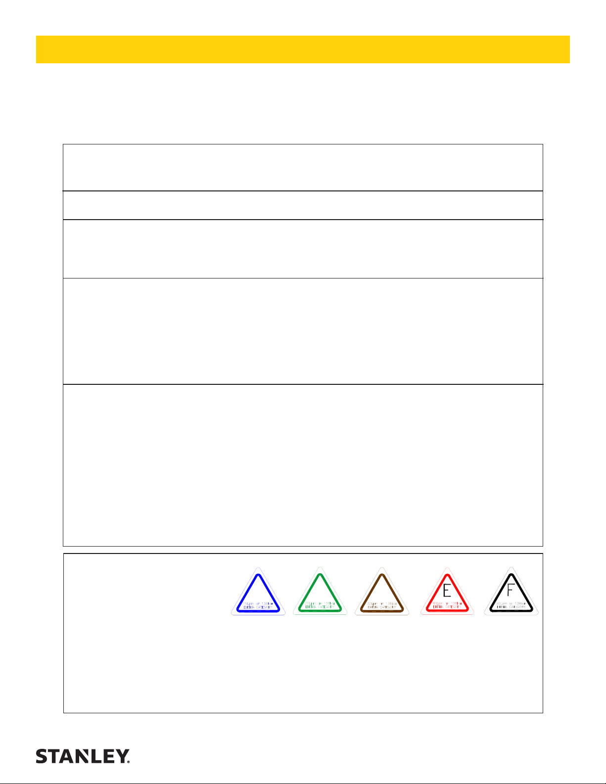
TOOL STICKERS & TAGS
12412 DANGER DECAL
30136
ROTATION DIRECTION
DECAL
D
30 LPM @ 138BAR
EHTMA CATEGORY
11207 CIRCUIT
TYPE D DECAL (CE)
08153 IW16 NAME TAG (US & CE)
12535 CIRCUIT
TYPE E DECAL (CE)
25610 RAILROAD
HELP DESK DECAL
66305 SOUND
POWER LEVEL
DECAL (CE)
28323 CE DECAL
(CE)
28788
MANUAL DECAL
(CE)
09612 GPM DECAL
NOTE:
THE INFORMATION LISTED ON THE STICKERS
SHOWN, MUST BE LEGIBLE AT ALL TIMES.
REPLACE DECALS IF THEY BECOME WORN OR
DAMAGED. REPLACEMENTS ARE AVAILABLE FROM
YOUR LOCAL STANLEY DISTRIBUTOR.
The safety tag (P/N 15875) at right is attached to the tool
when shipped from the factory. Read and understand the
safety instructions listed on this tag before removal. We
suggest you retain this tag and attach it to the tool when not
in use.
6 ► IW16 User Manual
SAFETY TAG P/N 15875 (shown smaller then actual size)
Page 7

HOSE TYPES
The rated working pressure of the hydraulic hose must be equal to or higher than the relief valve setting on the hydraulic system. There are three types of hydraulic hose that meet this requirement and are authorized for use with
Stanley Hydraulic Tools. They are:
Certied non-conductive — constructed of thermoplastic or synthetic rubber inner tube, synthetic ber braid
reinforcement, and weather resistant thermoplastic or synthetic rubber cover. Hose labeled certied non-
conductive is the only hose authorized for use near electrical conductors.
Wire-braided (conductive) — constructed of synthetic rubber inner tube, single or double wire braid reinforcement, and weather resistant synthetic rubber cover. This hose is conductive and must never be used near
electrical conductors.
Fabric-braided (not certied or labeled non-conductive) — constructed of thermoplastic or synthetic rubber inner tube, synthetic ber braid reinforcement, and weather resistant thermoplastic or synthetic rubber cover. This
hose is not certied non-conductive and must never be used near electrical conductors.
HOSE SAFETY TAGS
To help ensure your safety, the following DANGER tags are attached to all hose purchased from Stanley Hydraulic
Tools. DO NOT REMOVE THESE TAGS.
If the information on a tag is illegible because of wear or damage, replace the tag immediately. A new tag may be
obtained from your Stanley Distributor.
THE TAG SHOWN BELOW IS ATTACHED TO “CERTIFIED NON-CONDUCTIVE” HOSE
DANGER
1. FAILURE TO USE HYDRAULIC HOSE LABELED AND CERTIFIED AS NON-CONDUCTIVE
WHEN USING HYDRAULIC TOOLS ON OR NEAR ELECTRIC LINES MAY RESULT IN
DEATH OR SERIOUS INJURY.
FOR PROPER AND SAFE OPERATION MAKE SURE THAT YOU HAVE BEEN PROPERLY TRAINED IN CORRECT PROCEDURES REQUIRED FOR WORK ON OR AROUND
ELECTRIC LINES.
2. BEFORE USING HYDRAULIC HOSE LABELED AND CERTIFIED AS NON-CONDUCTIVE
ON OR NEAR ELECTRIC LINES. WIPE THE ENTIRE LENGTH OF THE HOSE AND FITTING WITH A CLEAN DRY ABSORBENT CLOTH TO REMOVE DIRT AND MOISTURE AND
TEST HOSE FOR MAXIMUM ALLOWABLE CURRENT LEAKAGE IN ACCORDANCE WITH
SAFETY DEPARTMENT INSTRUCTIONS.
DO NOT REMOVE THIS TAG
SEE OTHER SIDE
SIDE 1
3. DO NOT EXCEED HOSE WORKING PRESSURE OR ABUSE HOSE. IMPROPER USE
OR HANDLING OF HOSE COULD RESULT IN BURST OR OTHER HOSE FAILURE.
KEEP HOSE AS FAR AWAY AS POSSIBLE FROM BODY AND DO NOT PERMIT DIRECT
CONTACT DURING USE. CONTACT AT THE BURST CAN CAUSE BODILY INJECTION
AND SEVERE PERSONAL INJURY.
4. HANDLE AND ROUTE HOSE CAREFULLY TO AVOID KINKING, ABRASION, CUTTING, OR
CONTACT WITH HIGH TEMPERATURE SURFACES. DO NOT USE IF KINKED. DO NOT
USE HOSE TO PULL OR LIFT TOOLS, POWER UNITS, ETC.
5. CHECK ENTIRE HOSE FOR CUTS CRACKS LEAKS ABRASIONS, BULGES, OR DAMAGE TO COUPLINGS IF ANY OF THESE CONDITIONS EXIST, REPLACE THE HOSE
IMMEDIATELY. NEVER USE TAPE OR ANY DEVICE TO ATTEMPT TO MEND THE HOSE.
6. AFTER EACH USE STORE IN A CLEAN DRY AREA.
(Shown smaller than actual size)
DANGER
DANGER
SEE OTHER SIDE
SIDE 2
THE TAG SHOWN BELOW IS ATTACHED TO “CONDUCTIVE” HOSE.
DANGER
DANGER
1. DO NOT USE THIS HYDRAULIC HOSE ON OR NEAR ELECTRIC LINES. THIS HOSE IS
NOT LABELED OR CERTIFIED AS NON-CONDUCTIVE. USING THIS HOSE ON OR NEAR
ELECTRICAL LINES MAY RESULT IN DEATH OR SERIOUS INJURY.
2. FOR PROPER AND SAFE OPERATION MAKE SURE THAT YOU HAVE BEEN PROPERLY
TRAINED IN CORRECT PROCEDURES REQUIRED FOR WORK ON OR AROUND ELECTRIC LINES.
3. DO NOT EXCEED HOSE WORKING PRESSURE OR ABUSE HOSE. IMPROPER USE OR
HANDLING OF HOSE COULD RESULT IN BURST OR OTHER HOSE FAILURE. KEEP HOSE
AS FAR AWAY AS POSSIBLE FROM BODY AND DO NOT PERMIT DIRECT CONTACT
DURING USE. CONTACT AT THE BURST CAN CAUSE BODILY INJECTION AND SEVERE
PERSONAL INJURY.
4. HANDLE AND ROUTE HOSE CAREFULLY TO AVOID KINKING, CUTTING, OR CONTACT
WITH HIGH TEMPERATURE SURFACES. DO NOT USE IF KINKED. DO NOT USE HOSE TO
PULL OR LIFT TOOLS, POWER UNITS, ETC.
DO NOT REMOVE THIS TAG
SEE OTHER SIDE
SIDE 1
5. CHECK ENTIRE HOSE FOR CUTS CRACKS LEAKS ABRASIONS, BULGES, OR DAMAGE TO
COUPLINGS IF ANY OF THESE CONDITIONS EXIST, REPLACE THE HOSE IMMEDIATELY.
NEVER USE TAPE OR ANY DEVICE TO ATTEMPT TO MEND THE HOSE.
6. AFTER EACH USE STORE IN A CLEAN DRY AREA.
(Shown smaller than actual size)
DANGER
SEE OTHER SIDE
SIDE 2
DO NOT REMOVE THIS TAG
DO NOT REMOVE THIS TAG
IW16 User Manual ◄ 7
Page 8

Min. Working Pressure
USE
(Press/Return)
HOSE RECOMMENDATIONS
Certied Non-Conductive Hose - Fiber Braid - for Utility Bucket Trucks
Oil Flow Hose Lengths Inside Diameter
GPM LPM FEET METERS INCH MM PSI BAR
4-9 15-34 up to 10 up to 3 3/8 10 Both 2250 155
Conductive Hose - Wire Braid or Fiber Braid -DO NOT USE NEAR ELECTRICAL CONDUCTORS
4-6 15-23 up to 25 up to 7.5 3/8 10 Both 2500 175
4-6 15-23 26-100 7.5-30 1/2 13 Both 2500 175
5-10.5 19-40 up to 50 up to 15 1/2 13 Both 2500 175
5-10.5 19-40 51-100 15-30 5/8 16 Both 2500 175
5/8 16 Pressure 2500 175
3/4 19 Return 2500 175
5-10.5 19-40 100-300 30-90
10-13 38-49 up to 50 up to 15 5/8 16 Both 2500 175
5/8 16 Pressure 2500 175
3/4 19 Return 2500 175
10-13 38-49 51-100 15-30
3/4 19 Pressure 2500 175
1 25.4 Return 2500 175
10-13 38-49 100-200 30-60
5/8 16 Pressure 2500 175
3/4 19 Return 2500 175
13-16 49-60 up to 25 up to 8
3/4 19 Pressure 2500 175
1 25.4 Return 2500 175
13-16 49-60 26-100 8-30
PRESSURE
<<< FLOW
RETURN
FLOW >>>
Figure 1. Typical Hose Connections
Tool to Hydraulic Circuit Hose
Recommendations
The chart to the right shows recommended
minimum hose diameters for various hose
lengths based on gallons per minute (gpm)/
liters per minute (lpm). These recommenda-
tions are intended to keep return line pressure
(back pressure) to a minimum acceptable lev-
el to ensure maximum tool performance.
8 ► IW16 User Manual
This chart is intended to be used for hydraulic
tool applications only based on Stanley Hy-
draulic Tools tool operating requirements and
should not be used for any other applications.
All hydraulic hose must have at least a rated
minimum working pressure equal to the maxi-
mum hydraulic system relief valve setting.
All hydraulic hose must meet or exceed
specications as set forth by SAE J517.
Page 9
HTMA / EHTMA REQUIREMENTS
HTMA / EHTMA REQUIREMENTS
HTMA
HYDRAULIC SYSTEM REQUIREMENTS
Flow Range
Nominal Operating Pressure
(at the power supply outlet)
System relief valve setting
(at the power supply outlet)
Maximum back pressure
(at tool end of the return hose)
Measured at a max. uid viscosity of:
(at min. operating temperature)
Temperature: Sufcient heat rejection
capacity to limit max. uid temperature to:
(at max. expected ambient temperature)
Min. cooling capacity at a temperature
difference of between ambient and uid
temps
NOTE:
Do not operate the tool at oil temperatures above 140° F (60° C). Operation at higher temperatures can cause operator
discomfort at the tool.
Filter
Min. full-ow ltration
Sized for ow of at least:
(For cold temp. startup and max.
dirt-holding capacity)
4-6 gpm 7-9 gpm 9-10.5 gpm 11-13 gpm
(15-23 lpm) (26-34 lpm) (34-40 lpm) (42-49 lpm)
1500 psi 1500 psi 1500 psi 1500 psi
(103 bar) (103 bar) (103 bar) (103 bar)
2100-2250 psi 2100-2250 psi 2200-2300 psi 2100-2250 psi
(145-155 bar) (145-155 bar) (152-159 bar) (145-155 bar)
250 psi 250 psi 250 psi 250 psi
(17 bar) (17 bar) (17 bar) (17 bar)
400 ssu* 400 ssu* 400 ssu* 400 ssu*
(82 centistokes) (82 centistokes) (82 centistokes) (82 centistokes)
140° F 140° F 140° F 140° F
(60° C) (60° C) (60° C) (60° C)
3 hp 5 hp 6 hp 7 hp
(2.24 kW) (3.73 kW) (5.22 kW) (4.47 kW)
40° F 40° F 40° F 40° F
(22° C) (22° C) (22° C) (22° C)
25 microns 25 microns 25 microns 25 microns
30 gpm 30 gpm 30 gpm 30 gpm
(114 lpm) (114 lpm) (114 lpm) (114 lpm)
TYPE I TYPE II
TOOL TYPE
TYPE RR
TYPE III
Hydraulic uid Petroleum based
(premium grade, anti-wear, non-conductive)
Viscosity (at min. and max. operating temps)
NOTE:
When choosing hydraulic uid, the expected oil temperature extremes that will be experienced in service determine the
most suitable temperature viscosity characteristics. Hydraulic uids with a viscosity index over 140 will meet the requirements
over a wide range of operating temperatures.
*SSU = Saybolt Seconds Universal
EHTMA
100-400 ssu* 100-400 ssu* 100-400 ssu* 100-400 ssu*
(20-82 centistokes)
CLASSIFICATION
HYDRAULIC SYSTEM
REQUIREMENTS
Flow Range
Nominal Operating Pressure
(at the power supply outlet)
System relief valve setting
(at the power supply outlet)
NOTE: These are general hydraulic system requirements. See tool specication page for tool specic requirements
B
3.5-4.3 gpm 4.7-5.8 gpm 7.1-8.7 gpm 9.5-11.6 gpm 11.8-14.5 gpm
(13.5-16.5 lpm) (18-22 lpm) (27-33 lpm) (36-44 lpm) (45-55 lpm)
1870 psi 1500 psi 1500 psi 1500 psi 1500 psi
(129 bar) (103 bar) (103 bar) (103 bar) (103 bar)
2495 psi 2000 psi 2000 psi 2000 psi 2000 psi
(172 bar) (138 bar) (138 bar) (138 bar) (138 bar)
C
D
IW16 User Manual ◄ 9
Page 10

WRENCH TORQUE INFORMATION
FACTORS THAT AFFECT TORQUE
An impact wrench is a rotary hammer that impacts the
head of a bolt or nut. It does not apply a slow steady
torque as a standard torque wrench. Therefore, several factors affect the result of torque when using impact
wrenches:
1. LONG BOLTS. Long bolts having high-friction
threads with lubrication under the bolt head or associated nut can twist when impacted, then untwist
before the next impact. This will especially happen if
there is low friction between the bolt head or nut and
the mating surface.
2. HEAVY, LOOSE OR MULTIPLE ADAPTERS.
Heavy, loose or multiple adapters between the
wrench and socket can dissipate the intensity of the
impact to the bolt head or nut.
3. AMOUNT OF IMPACT. Maximum torque results can
be obtained by allowing continuous impacting of the
socket against the bolt head or nut for at least 10
seconds.
4. HYDRAULIC FLOW RATE. If the ow rate to the
tool is too low, the hammer (or impact) speed is re-
duced. If the ow is correct, a change in the relief
pressure does not affect the impact force. Poorly
designed hydraulic circuits can result in lower ow
rates and reduced impact speeds when pressure is
required during impacting.
BOLT GRADE AND THREAD
RECOMMENDATIONS
Allowable bolt torque is limited by both bolt thread diameter and grade of steel in the bolt. The IW16 Impact
Wrench is recommended for use on the following bolt
grade and thread sizes:
SAE Grade 2 1-1/8 to 1-7/8 inch / 28.5 / 47.6
mm
SAE Grade 5 1 to 1-5/8 inch / 25.4-41.2 mm
SAE Grade 8 7/8 to 1-3/8 inch / 22.2-35 mm
PREOPERATION PROCEDURES
CHECK POWER SOURCE
1. Using a calibrated ow meter and pressure gauge,
check that the hydraulic power source develops a
ow of 7–12 gpm / 20-45 lpm at 1000–2000 psi /
70–140 bar.
2. Make certain that the hydraulic power source is
equipped with a relief valve set to open at 2100
psi/145 bar minimum.
3. Check that the hydraulic circuit matches the tool for
open-center (OC) operation.
4. UNDERWATER MODELS ONLY. Make certain
that the wrench impact mechanism is cleaned and
greased with waterproof grease after each day’s
use.
CONNECT HOSES
1. Wipe all hose couplers with a clean, lint-free cloth
before making connections.
2. Connect hoses from the hydraulic power source to
the tool ttings or quick disconnects. It is good practice to connect the return hose rst and disconnect it
last to minimize or eliminate trapped pressure within
the wrench.
3. Observe the ow indicators stamped on the main
body assembly and the hose couplers to ensure
that the ow is in the proper directions. The female
couple on the tools “IN” port is the inlet (pressure)
coupler.
NOTE:
If the uncoupled hoses are left in the sun, pressure
increase within the hoses can make them difcult to
connect. Whenever possible, connect the free ends
of hoses together.
WRENCH OPERATION
The IW16 is designed for 1-inch square hex drive. The
1-inch drive conguration is used with drive sockets for
high impact (500–2500 ft lb / 680–3400 Nm) installation
and removal of fasteners.
During normal operation it is common to see some
grease leakage from around the anvil during hard use.
Refer to the IW16 Service Manual for the correct lubrication procedures.
Use at the low end of the 500–2500 ft lb / 680–3400
Nm torque range during continuous use over long periods of time (impact times exceeding 10 seconds). The
high temperature generated in the impact mechanism
can reduce steel part and lubricant durability within the
wrench.
1. Observe all Safety Precautions.
2. Move the hydraulic circuit control valve to the “ON”
position to operate the wrench.
10 ► IW16 User Manual
Page 11

WRENCH OPERATION
WARNING
Always use sockets and accessories designed for
impact type applications. DO NOT USE STANDARD
SOCKETS OR ACCESSORIES. THESE CAN
CRACK OR FRACTURE DURING OPERATION.
3.
Select the direction of impact desired using the reversing valve located on the side of the wrench. To
select clockwise direction, place the valve in the upward position. To select counter-clockwise direction,
place the valve in the downward position.
NOTE:
To more accurately tighten bolts, lubricate threads,
check with a torque wrench and duplicate time of
impacting for other bolts of the same length and
thread size.
4. Squeeze the trigger to activate the wrench.
5. Release the trigger to stop the wrench.
COLD WEATHER OPERATION
If the wrench is to be used during cold weather, preheat
the hydraulic uid at low engine speed. When using the
normally recommended uids, uid temperature should
be at or above 50° F/10° C (400 ssu/82 centistokes) before use.
Damage to the hydraulic system or wrench can result
from use with uid that is too viscous or too thick.
POST OPERATION—UNDERWATER
MODELS ONLY
The wrench impact mechanism must be cleaned and
greased with waterproof grease after every day of use.
The main housing valve and motor are sealed and do
not require maintenance unless they are malfunctioning.
Remove, clean, grease and assemble the impact mechanism as described in the IW16 Service Manual.
EXTENSION HANDLE
If the handle and anchor block are removed, all valve
handle/motor housing bolts must be cleaned, installed
with 242 Loctite® and re-torqued. Contact Stanley authorized service for procedure.
IW16 User Manual ◄ 11
Page 12

NOTICE
TOOL PROTECTION & CARE
In addition to the Safety Precautions found in this
manual, observe the following for
equipment protection and care.
• Make sure all couplers are wiped clean before connection.
• The hydraulic circuit control valve must be in the
“OFF” position when coupling or uncoupling hydraulic tools. Failure to do so may result in damage to
the quick couplers and cause overheating of the hydraulic system.
• Always store the tool in a clean dry space, safe from
damage or pilferage.
• Make sure the circuit PRESSURE hose (with male
quick disconnect) is connected to the “IN” port. The
circuit RETURN hose (with female quick disconnect)
is connected to the opposite port. Do not reverse cir-
cuit ow. This can cause damage to internal seals.
• Always replace hoses, couplings and other parts
with replacement parts recommended by Stanley
Hydraulic Tools. Supply hoses must have a minimum working pressure rating of 2500 psi/172 bar.
• Do not exceed the rated ow (see Specications) in
this manual for correct ow rate and model number.
Rapid failure of the internal seals may result.
• Always keep critical tool markings, such as warning
stickers and tags legible.
• Tool repair should be performed by experienced
personnel only.
• Make certain that the recommended relief valves
are installed in the pressure side of the system.
• Do not use the tool for applications for which it was
not intended.
12 ► IW16 User Manual
Page 13

TROUBLESHOOTING
If symptoms of poor performance develop, the following chart can be used as a guide to correct the problem. When
diagnosing faults in operation of the wrench, always check that the hydraulic power source is supplying the correct
hydraulic ow and pressure to the tool as listed in the following table. Use a ow meter known to be accurate. Check
the ow with the hydraulic uid temperature at least 80 ° F/27 ° C.
PROBLEM CAUSE SOLUTION
Low performance or impact. Incorrect hydraulic ow. Check that the hydraulic power source
is producing 7-12 gpm/20-45 lpm at
1500-2000 psi/105-140 bar.
Defective quick disconnects. Check each quick disconnect.
Worn impact mechanism. Repair or replace the impact mecha-
nism. See Service Mechanism Removal
Cleaning and Installation procedure to
extend mechanism life.
Hammer pins broken. Replace with integral frame (with pins).
Check relief adjustment screw setting.
Job may require a larger wrench.
Incorrect grease or periodic maintenance of the impact mechanism is not
being performed.
Spools incorrectly installed. Valve(s) incorrectly reassembled. See
Sockets or adapters too heavy or
loose.
Long bolt with lubricated head. Lubricate threads only.
Wrench runs too fast. Impact
mechanism or screws broken.
Grease leaks at anvil busing,
wrench warm.
Grease leaks at anvil bushing,
wrench cold.
Oil leak at motor cap face. Fasteners loose. Tighten to recommended torque.
Oil leaks at reversing spool. Damaged O-rings. Replace as required. Check Service
Incorrect hydraulic ow (too high). Check that hydraulic power source is
Supply and return hoses reversed. Install hoses correctly. Refer to Opera-
Relief sleeve or spring damaged. Remove and replace spool assembly.
Adjusting screw is in too far. Adjust correctly.
Hard duty cycle and heat forces
grease out.
Main shaft O-ring leaking. Replace as required.
Face O-ring worn or missing. Replace as required.
Motor cap/main housing damaged. Replace as required.
Wrong hydraulic uid. Circuit too hot. Refer to Operation section for correct
See Service Manual.
Service Manual.
Use the correct impact type sockets or
adapters.
producing 7-12 gpm/20-45 lpm at 15002000 psi/105-140 bar.
tion section in this manual.
Normal unless greasing instructions in
Service Manual are not followed.
Manual to avoid cutting O-rings on cross
holes in the spool bore.
uid/circuit specications.
IW16 User Manual ◄ 13
Page 14

SPECIFICATIONS
Drive Size .................................................................................................................................... 1-inch Square Drive
Weight ......................................................................................................................................................26 lbs/12 kg
Overall Length ................................................................................................................................ 14-1/2-inch/37 cm
Width .......................................................................................................................................................4-inch/11 cm
Pressure Range................................................................................................................1500-2000 psi/105-140 bar
Flow Range .................................................................................................................................7-12 gpm/20-45 lpm
Optimum Flow ....................................................................................................................................... 8 gpm/30 lpm
System Type ........................................................................................ Open and Closed Center, HTMA Type II or III
Porting ....................................................................................................................................................8 SAE O-ring
Output Speed (free spin) ...................................................................................................2000 rpm at 5 gpm/19 lpm
Input Speed ......................................................................................................................... 1200 Impacts per Minute
Connect Size and Type ....................................................................................................3/8-inch Male Pipe Adapter
Torque...........................................................................................................................500–2500 ft. lb/680–3400 Nm
SOUND AND VIBRATION DECLARATION
Test conducted on IW16157, S/N 9524, operated at standard 10 gpm input
Measured A-weighted sound power level, Lwa (ref. 1pW) in decibels 113.2 dBA
Uncertainty, Kwa, in decibels 3 dBA
Measured A-weighted sound pressure level, Lpa (ref. 20 µPa) at operator’s position,
in decibels
Uncertainty, Kpa, in decibels 3 dBA
Values determined according to noise test code given in ISO 15744, using the basic standard ISO 3744
NOTE: The sum of a measured noise emission value and its associated uncertainty represents an upper bound-
ary of the range of values which is likely to occur in measurements.
Declared vibration emission value in accordance with EN 12096
102.2 dBA
Measured vibration emission value: a 49 m/sec²
Uncertainty: K 5.2 m/sec²
Values determined according to ISO 8662-7
14 ► IW16 User Manual
Page 15
ACCESSORIES
Description Part Number
Adapter, 1-inch to 3/4-inch Drive .......................................................................................................................31201
Extension, 10 inch, 1-inch Drive ....................................................................................................................... 31203
Socket Retainer Pin, 1-inch Square Drive Socket ............................................................................................. 33276
Socket Retainer Ring, 1-inch Square Drive Socket ........................................................................................... 33277
SOCKETS
1-inch Square Drive 4-point Rectangular Head Lag Screw Socket 7/8 in. x 1-1/8 in...........................................66318
1-inch Square Drive 8-Point Deep × 1-5/16 inch ............................................................................................... 25203
1-inch Square Drive 8-Point Deep × 1-3/8 inch ................................................................................................. 25204
1-inch Square Drive 8-Point Deep × 1-1/2 inch ................................................................................................. 25205
1-inch Square Drive 8-Point Deep × 1-9/16 inch ............................................................................................... 25206
1-inch Square Drive 8-Point Deep × 1-7/8 inch ................................................................................................. 25208
1-inch Square Drive 8-Point Deep × 2 inch .......................................................................................................25209
1-inch Square Drive 8-Point Deep × 2-1/8 inch ................................................................................................. 25210
1-inch Square Drive 8-Point Deep × 2-3/16 inch ............................................................................................... 25211
1-inch Square Drive 8-Point Deep × 2-1/4 inch ................................................................................................. 25212
1-inch Square Drive 8-Point Deep × 1-5/8 inch ................................................................................................. 25216
1-inch Square Drive 8-Point Deep × 1-13/16 inch ............................................................................................. 25217
1-inch Square Drive 8-Point Deep × 1-11/16 inch ............................................................................................. 25218
1-inch Square Drive #70 Torx ............................................................................................................................26456
1-inch Square Drive 8-Point Deep × 1-1/4 inch ................................................................................................. 26529
1-inch Square Drive 4-Point Deep × 1 inch .......................................................................................................27710
Socket Sets
Socket Set, Includes 6 Sockets ......................................................................................................................... 33230
(25211, 25216, 25217, 25218, 26456, 27710)
Upright Handle Assy Kit...............................................72768
(Includes Upright Handle, decals, bolts, washers and Inst.)
IW16 User Manual ◄ 15
Page 16
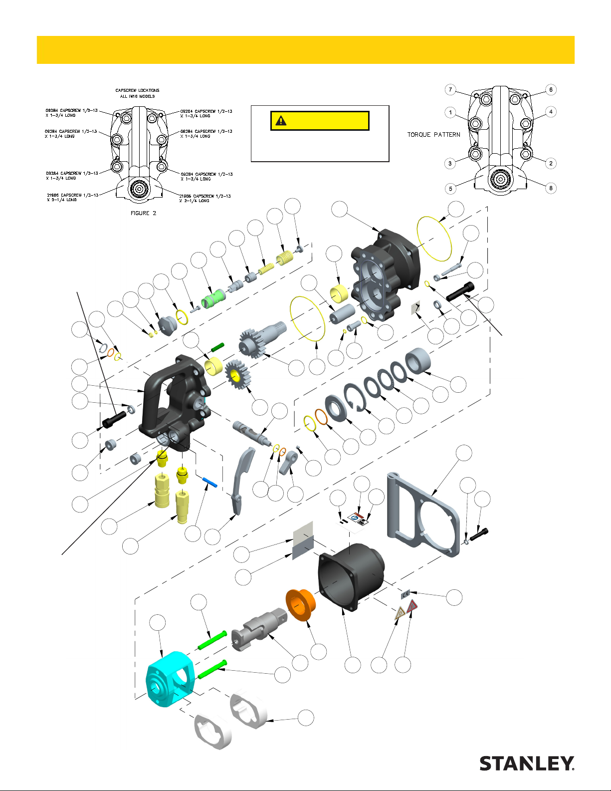
CAUTION
IW16 PARTS ILLUSTRATION
Make sure the correct capscrew is used
in the correct location
TORQUE TO 55 ft lb IN
A CROSS PATTERN AS
SHOWN ABOVE
46
10
35
NOTE:
Item 43
See page
18 Before
Ordering
21
43
7
37
55
9
NOTE: Item 20 See page
18 Before Ordering
20
48
16
45
2
62
19
27
22
24
10
25
30
21
17
28
14
61
5
4
62
8
13
33
29
63
34
23
51
54
1
6
31
32
52
4
18
36
44
64
7
TORQUE TO 55 ft
lb IN A CROSS PATTERN AS SHOWN
ABOVE
49
31
53
3
39
NOTE: IF THE TOOL
IS EQUIPPED WITH
HOSE WHIPS OR
COUPLERS THEY CAN
BE INSTALLED IN ONE
OF TWO PORTS. THE
PORTS FACING DOWN
OR THE PORTS FACING
TO THE REAR, MAKE
SURE THE PLUGS (ITEM
# 55) ARE INSTALLED IN
THE PORTS WITHOUT
THE HOSES OR COUPLERS.
16 ► IW16 User Manual
11
12
59
15
58
26
41
38
58
57
60
56
47
40
50
42
Page 17
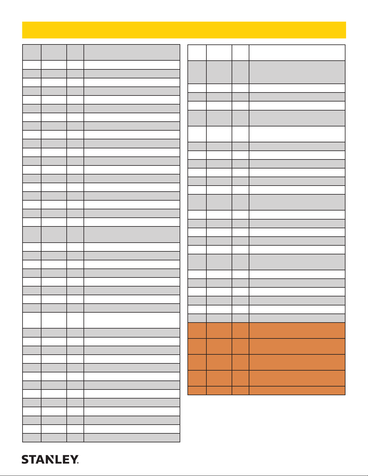
IW16 PARTS LIST
ITEM
NO.
1 00016 1 O-RING*
2 00026 1 O-RING*
3 00231 4 LOCKWASHER 5/16" I.D.
4 00255 2 O-RING*
5 00580 1 SETSCREW 1/4-20 X 1/4
6 00663 1 RETAINING RING
7 00697 8 LOCKWASHER 1/2" I.D
8 00717 1 O-RING*
9 00936 2 ADAPTER -8 (1/2) SAE X 3/8 NPT
10 01211 2 O-RING*
11 03972 1 COUPLER,3/8FEM. (SET 03971)
12 03973 1 COUPLER,3/8MALE (SET 03971)
13 04888 1 O-RING*
14 04939 1 LEVER
15 05965 1 ROLL PIN
16 06533 1 O-RING*
17 07982 1 SPRING REST
18 07984 1 RELIEF ADJUSTMENT SCREW
19 07986 1 RELIEF SEAT
20 73046 1 SPOOL (See page 18 before
21 08015 2 BACK-UP RING*
22 08122 1 COMPRESSION COIL SPRING
23 08125 1 SEAL BACK-UP WASHER*
24 08128 1 IDLER GEAR ASSY
25 08131 1 COMPRESSION COIL SPRING
26 08133 1 TRIGGER
27 08135 1 RELIEF POPPET
28 08136 1 MAIN SHAFT
29 08137 1 MOTOR HOUSING ASSY
30 08139 1 REVERSING SPOOL
31 08147 2 THRUST WASHER
32 08148 1 THRUST BEARING
33 08153 1 NAME TAG - IW16
34 08180 1 BACK-UP RING*
35 09275 1 RETAINING RING EXTERNAL
36 09277 1 HEX NUT 5/16-18UNC
37 09284 6 HSHCS 1/2-13 X 1-3/4
38 09612 1 GENERAL CAUTION STICKER
39 09625 4 HSHCS 5/16-18 X 1-1/2
40 11207 1 CIRCUIT TYPE "D" STICKER
41 12412 1 DANGER STICKER - ELECTRICAL
42 12535 1 CIRCUIT TYPE "E" STICKER
PART
NO.
QTY DESCRIPTION
ordering)
(INCLUDES ITEMS 61 THRU 64)
ITEM
NO.
43 73167 1 VALVE HANDLE ASSY (INCLUDES
44 21986 2 HSHCS 1/2-13 X 2-1/4
45 22063 1 SPOOL CAP
46 22064 1 ROD WIPER*
47 24682 1 HAMMER CASE, LAND (INCL ITEM
48 23678 1 HEADED PUSH PIN
49 23817 1 THRUST SPACER
50 28323_ 1 1 CE STICKER
51 28788 1 STICKER - MANUAL
52 30136 1 ROTATION DIRECTION STICKER
53 32087 1 ASSIST HANDLE
54 66305 1 GUARANTEED SOUND POWER
55 350237 2 HOLLOW HEX PLUG - 8 SAE
56 21010 1 BUSHING
57 24678 1 ANVIL
58 24680 2 HAMMER PINS
59 24679 1 HAMMER FRAME (INCLUDES ITEM
60 24677 2 HAMMER
61 08123 1 IDLER SHAFT
62 08146 2 BUSHING
63 07995 1 INSERT
64 03252 1 O-RING
SEAL KIT (P/N-09602)
* DENOTES PART IN SEAL KIT
PART
NO.
24758 1 HAMMER CASE U/W MODIFIED
21011 1 BUSHING (UNDERWATER)
72840 1 HAMMER FRAME ONLY
23134 1 STANDARD MECHANISM ASSY
24757 UNDERWATER MECHANISM (INCL
56725 2 HOSE ASSY for IW16150S (NOT
66727 2 HOSE ASSY for IW16150BN (NOT
47438 1 COUPLER SET FOR IW16150BN
QTY DESCRIPTION
ITEMS 55 and 62). SEE PAGE #18
BEFORE ORDERING
56)
(INCL BUSHING72762)
LEVEL 116 dBA
58 PINS)
(INCL ITEMS 47, & 56 THRU 60)
ITEMS 47 & 56 THRU 60)
PICTURED)
PICTURED)
IW16 User Manual ◄ 17
Page 18
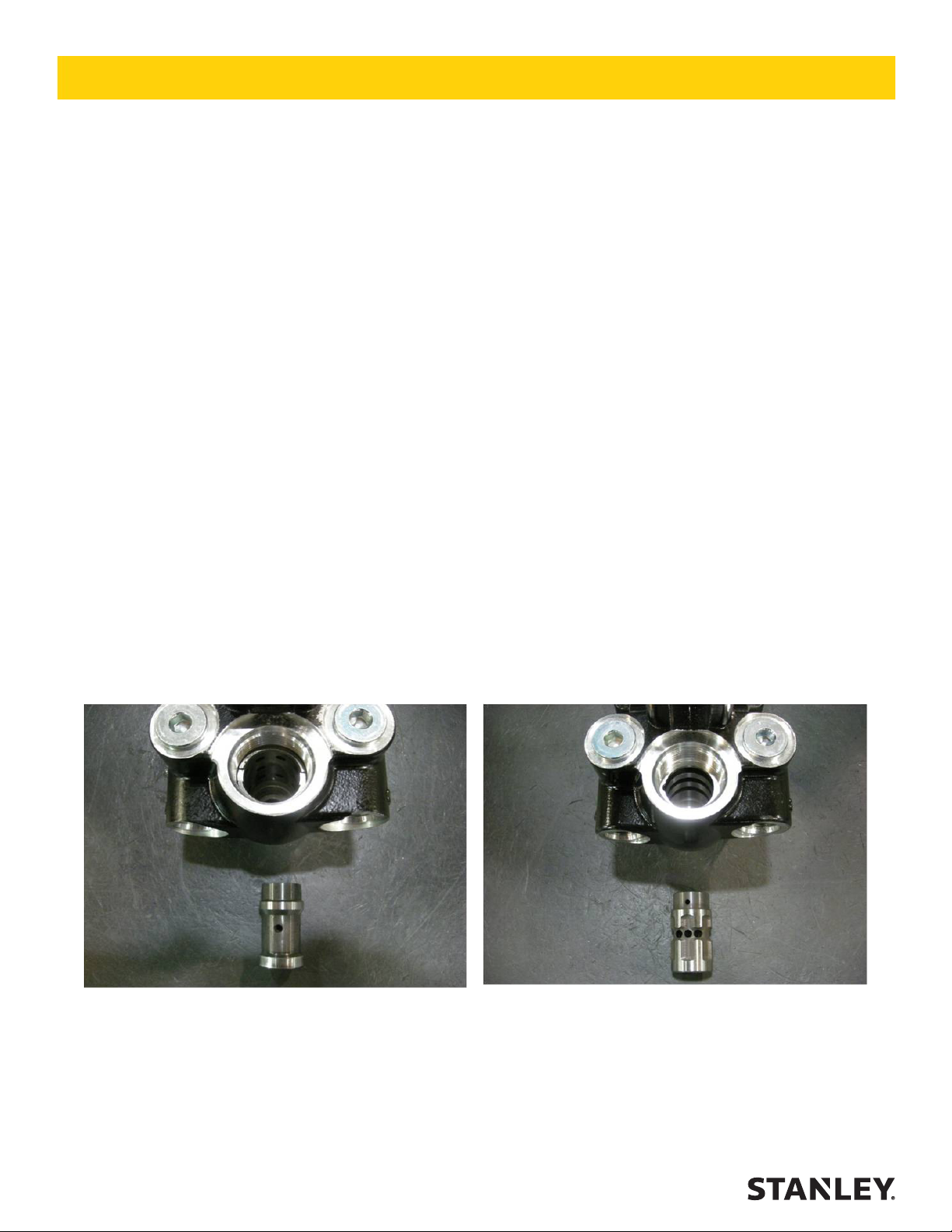
Old Style – No Longer Available
New Style – Uses no sleeve in spool bore.
VALVE HANDLE CHANGE NOTICE
ALL IW16 IMPACT WRENCH MODELS
Notication of change in valve handle assembly and on/off spool.
Part numbers and compatibility (March 2013).
Beginning at serial number 031513001, the valve handle assembly has changed. The prior style (part #
17279) used a steel spool sleeve installed in the valve handle assembly. The new style valve handle assembly (part # 73167) does not use a spool sleeve.
New style valve spool assembly (part # 73046) is required for use in the new style valve handle assembly.
The new style valve handle assembly will only accept new style on/off spool (PN 73046). If replacing old
style 17279 valve handle assembly with new style 73167, replacement of 73046 valve spool is also required.
New style on/off spool 73046 will t old style and new style valve handle assemblies. Old style valve spool
P/N 07998 is no longer available and substitutes to new style 73046.
Please refer to the photos below of the old style and new style valve handle and on/off spools.
Please contact the Technical Service Department at 503-659-5660 with any questions.
18 ► IW16 User Manual
Page 19
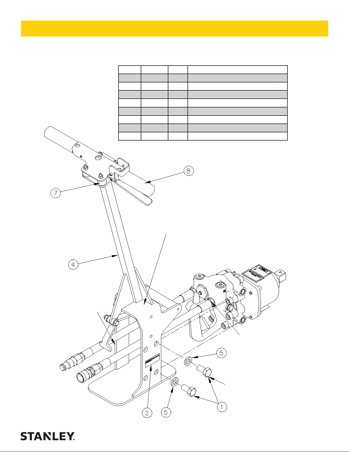
IW16 UPRIGHT HANDLE PARTS
IW16 UPRIGHT HANDLE KIT P/N-72768
ITEM P/N QTY DESCRIPTION
1 10792 2 BOLT 5/8-11 x 1-1/4
2 25610 1 RAILROAD HELPDESK STICKER
3 30136 1 DIRECTION STICKER
4 66037 1 UPRIGHT HANDLE W/TRIGGER LOCK
5 371071 2 LOCKWASHER 5/8 PLATED
6 72769 1 INST FOR P/N 72768
7 66035 4 ISOLATOR
8 31030 2 HANDLE GRIP
ITEM (3) “DIRECTION
STICKER”
GOES ON THIS SIDE OF
HANDLE
SAME AS ON THE TOOL
ROD ADJUSTMENT NUT IS LOCATED
IN THIS AREA OF THE UPRIGHT HANDLE
(NOT VISIBLE).
ADJUST ROD NUT UNTIL THE TRIGGER ON THE REMOTE HANDLE CAN
FULLY DEPRESS THE TRIGGER ON THE
WRENCH.
MAKE SURE HOSES ARE
INSTALLED INTO
REAR-FACING PORTS
TORQUE BOTH 5/8-11
BOLTS TO 90ft-lbs
IW16 User Manual ◄ 19
Page 20
UNDERWATER TOOLS DEPTH GUIDELINE
UNDERWATER MODELS ONLY
CAUTION
DO NOT USE HYDRAULIC TOOLS UNDER-
WATER THAT ARE NOT DESIGNATED AS
AN “UNDERWATER” MODEL, OR THIS
WILL RESULT IN DAMAGE TO THE TOOL.
For underwater hydraulic tools the applications are
broken down into four quadrants depending on
type of tool and method of operation.
The types of tools are percussive and rotational,
each with different characteristics allowing for different depth operation. With percussive tools, the
nitrogen accumulator PSI must counter the increase in ambient pressure found at lower depths.
Since there is a maximum PSI for percussive tools
they are limited to certain depths. Rotational tools
do not have accumulators and thus capable of
deeper depths.
Operation Overview
Percussive Rotational
Tools: Breakers,
Hammer Drills and
Chipping Hammers
Max Depth: 500' -
DiverROV
limitations due to
accumulator PSI
max (increase 40
PSI for every 100')
Tools: Breakers,
Hammer Drills and
Chipping Hammers
Max Depth: 500' limitations due to
accumulator PSI
max (increase 40
PSI for every 100')
Tools: Grinders,
Saws, Chain Saws
Max Depth: 1000' Reference hose
sizing guide below
Tools: Grinders,
Saws, Chain Saws
Max Depth: 1000' Reference hose
sizing guide below
The methods are broken into diver operated or
remote operated vehicle (ROV). ROV's can reach
lower depths and with an on-board hydraulic
power source that is depth compensated, can
operate hydraulic tools at depths of thousands of
feet. ROV operation is still limited to the tool, for
example a percussive tool has the same depth
limitation whether ROV or diver operated.
Recommended Hose Diameters
Depth (ft) 8 GPM 12 GPM
100 5/8” 5/8”
300 3/4” 1”
600 1” 1”
1000 1” 1-1/4”
20 ► IW16 User Manual
Page 21

NOTES
IW16 User Manual ◄ 21
Page 22

Stanley Hydraulic Tools
3810 SE Naef Road
Milwaukie, Oregon 97267-5698 USA
(503) 659-5660 / Fax (503) 652-1780
www.stanleyhydraulics.com
 Loading...