

Page 1
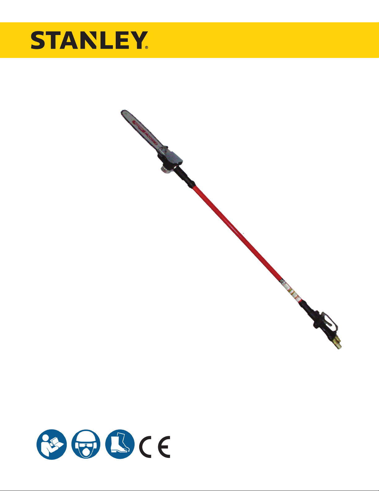
CS25/28
HYDRAULIC
POLE CHAIN SAW
USER MANUAL
Safety, Operation and Maintenance
© 2014 Stanley Black & Decker, Inc.
New Britain, CT 06053
U.S.A.
66205 8/2014 Ver. 9
Page 2

Weisbeck, Andy
Machinery Directive
2006/42/EC:2006
Self
DECLARATION OF CONFORMITY
DECLARATION OF CONFORMITY
ÜBEREINSTIMMUNGS-ERKLARUNG
DECLARATION DE CONFORMITE CEE
DECLARACION DE CONFORMIDAD
DICHIARAZIONE DI CONFORMITA
______________________________________________________________________
I, the undersigned:
Ich, der Unterzeichnende:
Je soussigné:
El abajo firmante:
lo sottoscritto:
hereby declare that the equipment specified hereunder:
bestätige hiermit, daß erklaren Produkt genannten Werk oder Gerät:
déclare que l’équipement visé ci-dessous:
Por la presente declaro que el equipo se especifica a continuación:
Dichiaro che le apparecchiature specificate di seguito:
Surname and First names/Familiennname und Vornamen/Nom et prénom /Nombre y apellido/Cognome e nome
Hydraulic Tools
1. Category:
Kategorie:
Catégorie:
Categoria:
Categoria:
2. Make/Marke/Marque/Marca/Marca
3. Type/Typ/Type/Tipo/Tipo: CS2581101, CS2881101
4. Serial number of equipment:
Seriennummer des Geräts:
Numéro de série de l’équipement:
Numero de serie del equipo:
Matricola dell´attrezzatura:
Has been manufactured in conformity with
Wurde hergestellt in Übereinstimmung mit
Est fabriqué conformément
Ha sido fabricado de acuerdo con
E’ stata costruita in conformitá con
Directive/Standards
Richtlinie/Standards
Directives/Normes
Directriz/Los Normas
Direttiva/Norme
Certificate
ISO
5. Special Provisions: None
Spezielle Bestimmungen:
Dispositions particulières:
Provisiones especiales:
Disposizioni speciali:
No.
Nr
Numéro
No
n.
0466/96/32-1:1998
11680-2:2000
Stanley
Pole Chain Saw, Hydraulic
All
Approved body
Prüfung durch
Organisme agréé
Aprobado
Collaudato
Self
Self
6. Representative in the Union: Patrick Vervier, Stanley Dubuis 17-19, rue Jules Berthonneau-BP 3406 41034 Blois Cedex, France.
Vertreter in der Union/Représentant dans l’union/Representante en la Union/Rappresentante presso l’Unione
Done at/Ort/Fait à/Dado en/Fatto a Stanley Hydraulic Tools, Milwaukie, Oregon USA
Signature/Unterschrift/Signature/Firma/Firma
Position/Position/Fonction/Cargo/Posizione Engineering Manager
2 ► CS25/28 User Manual
Date/Datum/le/Fecha/Data 3-3-11
Page 3
WARNING
TABLE OF CONTENTS
DECLARATION OF CONFORMITY .......................................................................................................................... 2
SAFETY SYMBOLS ..................................................................................................................................................4
SAFETY PRECAUTIONS .......................................................................................................................................... 5
ELECTRICAL HAZARDS ..........................................................................................................................................7
TOOL STICKERS & TAGS ........................................................................................................................................9
HOSE TYPES ..........................................................................................................................................................10
HOSE RECOMMENDATIONS ................................................................................................................................ 11
FIGURE 1. TYPICAL HOSE CONNECTIONS ..................................................................................................... 11
HTMA REQUIREMENTS .........................................................................................................................................12
OPERATION ............................................................................................................................................................13
FIGURE 2. FELLING A TREE .............................................................................................................................. 14
FIGURE 3. CROSSCUTTING LOGS/LIMBS WITH PRESSURE ON BOTTOM .................................................15
TOOL PROTECTION & CARE ................................................................................................................................17
TROUBLESHOOTING ............................................................................................................................................18
SPECIFICATIONS ................................................................................................................................................... 19
ACCESSORIES.......................................................................................................................................................19
SERVICE TOOLS ....................................................................................................................................................19
CS25/28 PARTS ILLUSTRATION ...........................................................................................................................20
CS25/28 PARTS LIST .............................................................................................................................................21
IMPORTANT
To ll out a Product Warranty Validation form, and for information on your warranty,
visit Stanleyhydraulics.com and select the Company tab, Warranty.
(NOTE: The warranty Validation record must be submitted to validate the warranty).
SERVICING: This manual contains safety, operation, and routine maintenance instructions. Stanley Hydraulic
Tools recommends that servicing of hydraulic tools, other than routine maintenance, must be performed by an au-
thorized and certied dealer. Please read the following warning.
SERIOUS INJURY OR DEATH COULD RESULT FROM THE IMPROPER REPAIR OR SERVICE OF THIS
TOOL.
REPAIRS AND / OR SERVICE TO THIS TOOL MUST ONLY BE DONE BY AN AUTHORIZED AND
CERTIFIED DEALER.
For the nearest authorized and certied dealer, call Stanley Hydraulic Tools at the number listed on the back of this
manual and ask for a Customer Service Representative.
CS25/28 User Manual ◄ 3
Page 4
DANGER
WARNING
CAUTION
CAUTION
NOTICE
IMPORTANT
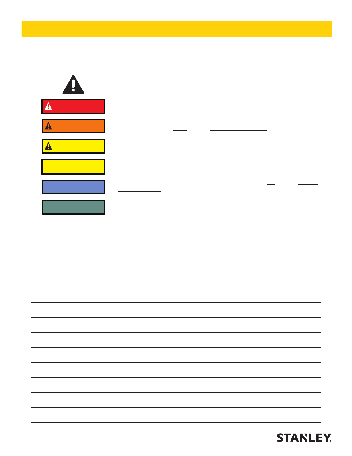
SAFETY SYMBOLS
Safety symbols and signal words, as shown below, are used to emphasize all operator, maintenance and repair actions which, if not strictly followed, could result in a life-threatening situation, bodily injury or damage to equipment.
This is the safety alert symbol. It is used to alert you to potential personal injury
hazards. Obey all safety messages that follow this symbol to avoid possible
injury or death.
This safety alert and signal word indicate an imminently hazardous situation
which, if not avoided, will result in death or serious injury.
This safety alert and signal word indicate a potentially hazardous situation
which, if not avoided, could result in death or serious injury.
This safety alert and signal word indicate a potentially hazardous situation
which, if not avoided, could result in death or serious injury.
This signal word indicates a potentially hazardous situation which, if not avoided, may result in property damage.
This signal word indicates a situation which, if not avoided, will result in damage
to the equipment.
This signal word indicates a situation which, if not avoided, may result in damage to the equipment.
Always observe safety symbols. They are included for your safety and for the protection of the tool.
LOCAL SAFETY REGULATIONS
Enter any local safety regulations here. Keep these instructions in an area accessible to the operator and maintenance personnel.
4 ► CS25/28 User Manual
Page 5

SAFETY PRECAUTIONS
Tool operators and maintenance personnel must always
comply with the safety precautions given in this manual
and on the stickers and tags attached to the tool and
hose.
These safety precautions are given for your safety. Review them carefully before operating the tool and before
performing general maintenance or repairs.
Supervising personnel should develop additional pre-
cautions relating to the specic work area and local
safety regulations. If so, place the added precautions in
the space provided in this manual.
The CS25/28 Hydraulic Pole Chain Saw will provide
safe and dependable service if operated in accordance
with the instructions given in this manual. Read and understand this manual and any stickers and tags attached
to the tool and hoses before operation. Failure to do so
could result in personal injury or equipment damage.
• Operator must start in a work area without bystand-
ers. The operator must be familiar with all prohibited
work areas such as excessive slopes and dangerous terrain conditions.
• Establish a training program for all operators to en-
sure safe operation.
• Do not operate the tool unless thoroughly trained or
under the supervision of an instructor.
• Always wear safety equipment such as goggles,
ear, head protection, and safety shoes at all times
when operating the tool.
• Do not overreach. Maintain proper footing and bal-
ance at all times.
• Do not inspect or clean the tool while the hydraulic
power source is connected. Accidental engagement
of the tool can cause serious injury.
• Supply hoses must have a minimum working pressure rating of 2500 psi/175 bar.
• Be sure all hose connections are tight.
• The hydraulic circuit control valve must be in the
OFF position when coupling or uncoupling the tool.
Wipe all couplers clean before connecting. Use only
lint-free cloths. Failure to do so may result in damage to the quick couplers and cause overheating of
the hydraulic system.
• Do not operate the tool at oil temperatures above
140 °F/60 °C. Operation at higher oil temperatures
can cause operator discomfort and may damage the
tool.
• Do not operate a damaged, improperly adjusted, or
incompletely assembled tool.
• To avoid personal injury or equipment damage, all
tool repair, maintenance and service must only be
performed by authorized and properly trained personnel.
• Do not exceed the rated limits of the tool or use the
tool for applications beyond its design capacity.
• Always keep critical tool markings, such as labels
and warning stickers legible.
• Always replace parts with replacement parts recommended by Stanley Hydraulic Tools.
• Check fastener tightness often and before each use
daily.
• Do not wear loose tting clothing when operating the
tool.
CS25/28 User Manual ◄ 5
Page 6

SAFETY PRECAUTIONS
POLE CHAIN SAW SPECIFIC
SAFETY PRECAUTIONS
• Do not rely exclusively upon the safety devices built
into the saw. As a pole saw user, several steps must
be taken to keep your cutting jobs free from accident
or injury.
• With basic understanding of kickback, you can reduce or eliminate the element of surprise. Sudden
surprise contributes to accidents.
• Keep a good rm grip on the pole chain saw with
both hands. Place your right hand on the rear handle and your left hand on the outer tube assembly
when operating. Use a rm grip with your thumbs
and ngers encircling the chain saw handle and outer tube assembly. A rm grip helps reduce kickback
and maintains control of the pole chain saw. Do not
let go.
• Make sure the area in which you are cutting is free
of obstructions. Never allow the nose of the guide
bar to contact a branch or any other obstruction that
can be accidently hit while operating the saw.
• Cut at the rated operating speeds (gpm).
• Follow the manufacturer’s sharpening and mainte-
nance instructions for the saw chain.
• Only use replacement bars and chains specied by
Stanley or equivalent.
• Make sure you’re well rested and mentally alert before operating the pole chain saw.
• Do not start cutting until you have a clear work area,
secure footing and a planned drop area for falling
branches.
• Keep all parts of the body away from the saw chain
during operation.
• Carry the saw with the unit de-energized.
• Do not operate a pole chain saw that is damaged,
improperly adjusted or not completely and securely
assembled. Make sure the chain stops moving when
the control trigger is released.
• Use extreme caution when cutting small branches.
Twigs may catch the saw chain and be whipped toward the operator or pull the operator off balance.
• When cutting a limb that is under tension, be aware
of spring back so you will not be struck when the
tension on the limb is released. Always cut on the
outside arc or curve.
• Keep the handle dry, clean and free of hydraulic
uid.
• When using tools near energized transmission lines,
make sure to use only hoses labeled and certied
non-conductive.
• Turn off the power unit or move the hydraulic control
valve to neutral before setting the pole chain saw
down.
• Use a chain bar scabbard when transporting the
saw.
• Know the location of buried or covered electrical
services before starting work.
• To avoid personal injury or equipment damage, all
tool repair, maintenance and service must only be
performed by authorized and properly trained personnel.
6 ► CS25/28 User Manual
Page 7

ELECTRICAL HAZARDS
The following guidelines must be followed to prevent
accidental contact with overhead electrical conductors
and/or communication wires and cables. (Ref. ANSI
Z133.1-2000)
WORKING IN PROXIMITY TO ELECTRICAL
HAZARDS
An inspection shall be made by a qualied arborist to
determine whether an electrical hazard exists before
climbing, or otherwise entering, or performing work in
or on a tree.
Only qualied line-clearance arborists or qualied line-
clearance arborist trainees shall be assigned to work
where an electrical hazard exists. Qualied line-clearance arborist trainees shall be under the direct supervi-
sion of qualied line-clearance arborist.
A second qualied line-clearance arborists or line-clear-
ance arborist trainees shall be within vision or voice
communication during line-clearing operations aloft
when line-clearance arborists or line-clearance arborist
trainees must approach closer than 10 feet (3.05 meters) to any energized electrical conductor in excess of
750 volts (primary conductor) or when:
1. Branches or limbs being removed cannot rst be
cut (with a pole pruner/pole saw) to sufciently clear
electrical conductors, so as to avoid contact.
2. Roping is required to remove branches or limbs
from such electrical conductors. This does not apply to individuals working on behalf of, or employed
by, electrical system owners/operators engaged in
line-clearing operations incidental to their normal
occupation.
Qualied line-clearance arborists and line-clearance
arborist trainees shall maintain minimum approach distances from energized electrical conductors in accordance with Table 1.
All other arborists shall maintain a minimum approach
distance from energized electrical conductors in accordance with Table 2.
Branches hanging on an energized electrical conductor
shall be removed using non-conductive equipment.
Table 1 – Minimum approach distances from energized conductors for qualied line-clearance arborists
and qualied line- clearance arborist trainees.
Nominal Voltage
(kV phase-to-
phase)
0.05 to 1.0 Avoid contact Avoid contact Avoid contact
1.1 to 15.0 2–04 0.71 2–08 0.81 2–10 0.86
15.1 to 36.0 2–09 0.84 3–02 0.97 3–05 1.04
36.1 to 46.0 3–00 0.92 3–05 1.04 3–09 1.14
46.1 to 72.5 3–09 1.14 4–03 1.30 4–07 1.40
72.6 to 121.0 4–06 1.37 5–02 1.58 5–07 1.70
138.0 to 145.0 5–02 1.58 5–11 1.80 6–05 1.96
161.0 to 169.0 6–00 1.83 6–10 2.08 7–05 2.26
230.0 to 242.0 7–11 2.41 9–00 2.75 9–09 2.97
345.0 to 362.0 13–02 4.02 15–00 4.58 16–03 4.96
500.0 to 550.0 19–00 5.80 21–09 6.63 23–06 7.17
765.0 to 800.0 27–04 8.34 31–03 9.53 33–10 10.32
Includes 1910.269 elevation
factor, sea level to 5000 ft
ft-in m ft-in m ft-in m
1) Exceeds phase-to-ground; elevation factor per 29 CFR 1910.269.
Includes 1910.269 elevation
1)
factor, 5001 – 10,000 ft
1)
Includes 1910.269 elevation
factor, 10,000 – 14,000 ft
1)
CS25/28 User Manual ◄ 7
Page 8

ELECTRICAL HAZARDS
Table 2 – Minimum approach distances to energized
conductors for persons other than qualied lineclearance arborists and qualied line-clearance ar-
borist trainees.
Nominal Voltage
kV phase-to-phase
0.0 – 1.0 10–00 3.05
1.1 – 15.0 10–00 3.05
15.1 – 36.0 10–00 3.05
36.1 – 50.0 10–00 3.05
50.1 – 72.5 10–09 3.28
72.6 – 121.0 12–04 3.76
138.0 – 145.0 13–02 4.00
161.0 – 169.0 14–00 4.24
230.0 – 242.0 16–05 4.97
345.0 – 362.0 20–05 6.17
500.0 – 550.0 26–08 8.05
785.0 – 800.0 35–00 10.55
1)
1)
Exceeds phase-to-ground.
Distance
ft-in m
The tie-in position should be above the work area and
located in such a way that a slip would swing the arborist
away from any energized electrical conductors or other
identied hazard.
While climbing, the arborist should climb on the side of
the tree that is away from energized electrical conductors as required in Tables 1 and 2.
Footwear, including lineman’s overshoes, having electrical-resistant soles, shall not be considered as providing
any measure of safety from electrical hazards.
Rubber gloves, with or without leather or other protective covering, shall not be considered as providing any
measure of safety from electrical hazards.
Ladders, platforms and aerial devices, including insulated aerial devices, shall be subject to minimum approach
distances in Table 1 and 2.
Aerial devices and attached equipment (such as chippers) contacting energized electrical conductors shall be
considered energized. Contact shall be avoided, except
where emergency rescue procedures are being carried
out. Emergency rescue should be performed in accordance with 4.3.
STORM WORK AND EMERGENCY
CONDITIONS-LINE CLEARANCE
Line clearance shall not be performed during adverse
weather conditions such as thunderstorms, high winds
and snow and ice storms.
Qualied line-clearance arborists and qualied line-
clearance arborists trainees performing line clearance
in the aftermath of a storm or under similar conditions
shall be trained in the special hazards associated with
this type of work.
Line-clearance operations shall be suspended when
storm work or emergency conditions develop involving
energized electrical conductors. Electrical system own-
ers/operators shall be notied immediately.
8 ► CS25/28 User Manual
Page 9
28409
Composite Decal
THIS CHAIN SAW IS
EQUIPPED WITH AN
AUTOMATIC CHAIN
OILER.
SEE YOUR PARTS &
SERVICE BOOK FOR
PROPER ADJUSTING
PROCEDURES
04746
Automatic Oiler
Decal
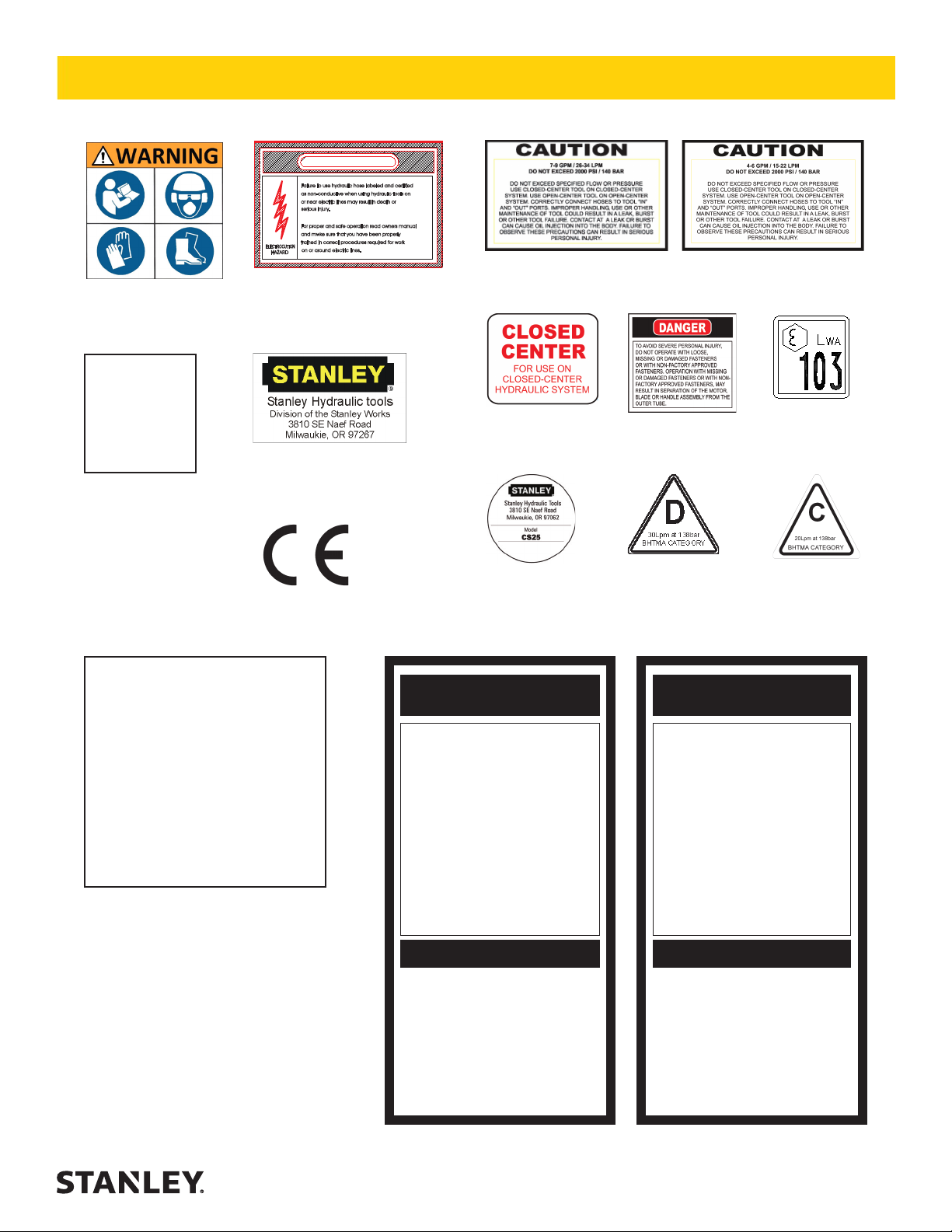
TOOL STICKERS & TAGS
DANGER
Failure to use hydraulic hoselabeled andcertified
as non-conductive when using hydraulictoolson
or near electric lines mayresultindeathor
serious injury.
Forproper and safe operationreadownersmanual
and mwke sure that youhave beenproperly
trained in correct procedures requiredfor work
ELECTROCUTION
on or around electric lines.
HAZARD
12412
Electrical Warning Decal
05153
Stanley Decal
03786
7–9 GPM Decal
03693
Closed Center Decal
03782
4–6 GPM Decal
15863
Danger Decal
34685
Sound Power
Decal
28323
CE Decal
NOTE:
THE INFORMATION LISTED
ON THE STICKERS SHOWN,
MUST BE LEGIBLE AT ALL
TIMES.
REPLACE DECALS IF
THEY BECOME WORN OR
DAMAGED. REPLACEMENTS
ARE AVAILABLE FROM
YOUR LOCAL STANLEY
DISTRIBUTOR.
The safety tag (P/N 15875) at right is
attached to the tool when shipped from
the factory. Read and understand the
safety instructions listed on this tag before
removal. We suggest you retain this tag and
attach it to the tool when not in use.
65839 – CS25 (shown)
65840 – CS28
Name Tag
1. FAILURE TO USE HYDRAULIC HOSE LABELED AND CERTIFIED AS NON-CONDUCTIVE WHEN USING HYDRAULIC
TOOLS ON OR NEAR ELECTRICAL LINES MAY RESULT IN
DEATH OR SERIOUS INJURY.
BEFORE USING HOSE LABELED AND CERTIFIED AS NON-
CONDUCTIVE ON OR NEAR ELECTRIC LINES BE SURE THE
HOSE IS MAINTAINED AS NON-CONDUCTIVE. THE HOSE
SHOULD BE REGULARLY TESTED FOR ELECTRIC CURRENT LEAKAGE IN ACCORDANCE WITH YOUR SAFETY
DEPARTMENT INSTRUCTIONS.
2. A HYDRAULIC LEAK OR BURST MAY CAUSE OIL INJECTION INTO THE BODY OR CAUSE OTHER SEVERE
PERSONAL INJURY.
A. DO NOT EXCEED SPECIFIED FLOW AND PRESSURE
FOR THIS TOOL. EXCESS FLOW OR PRESSURE MAY
CAUSE A LEAK OR BURST.
B. DO NOT EXCEED RATED WORKING PRESSURE OF
HYDRAULIC HOSE USED WITH THIS TOOL. EXCESS
PRESSURE MAY CAUSE A LEAK OR BURST.
C. CHECK TOOL HOSE COUPLERS AND CONNECTORS
DAILY FOR LEAKS. DO NOT FEEL FOR LEAKS WITH
YOUR HANDS. CONTACT WITH A LEAK MAY RESULT
IN SEVERE PERSONAL INJURY.
IMPORTANT
READ OPERATION MANUAL AND
SAFETY INSTRUCTIONS FOR THIS
TOOL BEFORE USING IT.
USE ONLY PARTS AND REPAIR
PROCEDURES APPROVED BY
STANLEY AND DESCRIBED IN THE
OPERATION MANUAL.
TAG TO BE REMOVED ONLY BY
TOOL OPERATOR.
SEE OTHER SIDE
11207
Circuit Type D
Decal
DANGERDANGER
D. DO NOT LIFT OR CARRY TOOL BY THE HOSES. DO
NOT ABUSE HOSE. DO NOT USE KINKED, TORN OR
DAMAGED HOSE.
3. MAKE SURE HYDRAULIC HOSES ARE PROPERLY CONNECTED TO THE TOOL BEFORE PRESSURING SYSTEM.
SYSTEM PRESSURE HOSE MUST ALWAYS BE CONNECTED TO TOOL “IN” PORT. SYSTEM RETURN HOSE
MUST ALWAYS BE CONNECTED TO TOOL “OUT” PORT.
REVERSING CONNECTIONS MAY CAUSE REVERSE
TOOL OPERATION WHICH CAN RESULT IN SEVERE
PERSONAL INJURY.
4. DO NOT CONNECT OPEN-CENTER TOOLS TO CLOSEDCENTER HYDRAULIC SYSTEMS. THIS MAY RESULT IN
LOSS OF OTHER HYDRAULIC FUNCTIONS POWERED BY
THE SAME SYSTEM AND/OR SEVERE PERSONAL INJURY.
5. BYSTANDERS MAY BE INJURED IN YOUR WORK AREA.
KEEP BYSTANDERS CLEAR OF YOUR WORK AREA.
6. WEAR HEARING, EYE, FOOT, HAND AND HEAD PROTECTION.
7. TO AVOID PERSONAL INJURY OR EQUIPMENT DAMAGE,
ALL TOOL REPAIR MAINTENANCE AND SERVICE MUST
ONLY BE PERFORMED BY AUTHORIZED AND PROPERLY
TRAINED PERSONNEL.
IMPORTANT
READ OPERATION MANUAL AND
SAFETY INSTRUCTIONS FOR THIS
TOOL BEFORE USING IT.
USE ONLY PARTS AND REPAIR
PROCEDURES APPROVED BY
STANLEY AND DESCRIBED IN THE
OPERATION MANUAL.
TAG TO BE REMOVED ONLY BY
TOOL OPERATOR.
SEE OTHER SIDE
11206
Circuit Type C
Decal
SAFETY TAG P/N 15875 (Shown smaller then actual size)
CS25/28 User Manual ◄ 9
Page 10

HOSE TYPES
The rated working pressure of the hydraulic hose must be equal to or higher than the relief valve setting on the hydraulic system. There are three types of hydraulic hose that meet this requirement and are authorized for use with
Stanley Hydraulic Tools. They are:
Certied non-conductive — constructed of thermoplastic or synthetic rubber inner tube, synthetic ber braid
reinforcement, and weather resistant thermoplastic or synthetic rubber cover. Hose labeled certied non-
conductive is the only hose authorized for use near electrical conductors.
Wire-braided (conductive) — constructed of synthetic rubber inner tube, single or double wire braid reinforcement, and weather resistant synthetic rubber cover. This hose is conductive and must never be used near
electrical conductors.
Fabric-braided (not certied or labeled non-conductive) — constructed of thermoplastic or synthetic rubber inner tube, synthetic ber braid reinforcement, and weather resistant thermoplastic or synthetic rubber cover. This
hose is not certied non-conductive and must never be used near electrical conductors.
HOSE SAFETY TAGS
To help ensure your safety, the following DANGER tags are attached to all hose purchased from Stanley Hydraulic
Tools. DO NOT REMOVE THESE TAGS.
If the information on a tag is illegible because of wear or damage, replace the tag immediately. A new tag may be
obtained from your Stanley Distributor.
THE TAG SHOWN BELOW IS ATTACHED TO “CERTIFIED NON-CONDUCTIVE” HOSE
DANGER
1. FAILURE TO USE HYDRAULIC HOSE LABELED AND CERTIFIED AS NON-CONDUCTIVE
WHEN USING HYDRAULIC TOOLS ON OR NEAR ELECTRIC LINES MAY RESULT IN
DEATH OR SERIOUS INJURY.
FOR PROPER AND SAFE OPERATION MAKE SURE THAT YOU HAVE BEEN PROPERLY TRAINED IN CORRECT PROCEDURES REQUIRED FOR WORK ON OR AROUND
ELECTRIC LINES.
2. BEFORE USING HYDRAULIC HOSE LABELED AND CERTIFIED AS NON-CONDUCTIVE
ON OR NEAR ELECTRIC LINES. WIPE THE ENTIRE LENGTH OF THE HOSE AND FITTING WITH A CLEAN DRY ABSORBENT CLOTH TO REMOVE DIRT AND MOISTURE AND
TEST HOSE FOR MAXIMUM ALLOWABLE CURRENT LEAKAGE IN ACCORDANCE WITH
SAFETY DEPARTMENT INSTRUCTIONS.
DO NOT REMOVE THIS TAG
SEE OTHER SIDE
SIDE 1
3. DO NOT EXCEED HOSE WORKING PRESSURE OR ABUSE HOSE. IMPROPER USE
OR HANDLING OF HOSE COULD RESULT IN BURST OR OTHER HOSE FAILURE.
KEEP HOSE AS FAR AWAY AS POSSIBLE FROM BODY AND DO NOT PERMIT DIRECT
CONTACT DURING USE. CONTACT AT THE BURST CAN CAUSE BODILY INJECTION
AND SEVERE PERSONAL INJURY.
4. HANDLE AND ROUTE HOSE CAREFULLY TO AVOID KINKING, ABRASION, CUTTING, OR
CONTACT WITH HIGH TEMPERATURE SURFACES. DO NOT USE IF KINKED. DO NOT
USE HOSE TO PULL OR LIFT TOOLS, POWER UNITS, ETC.
5. CHECK ENTIRE HOSE FOR CUTS CRACKS LEAKS ABRASIONS, BULGES, OR DAMAGE TO COUPLINGS IF ANY OF THESE CONDITIONS EXIST, REPLACE THE HOSE
IMMEDIATELY. NEVER USE TAPE OR ANY DEVICE TO ATTEMPT TO MEND THE HOSE.
6. AFTER EACH USE STORE IN A CLEAN DRY AREA.
(Shown smaller than actual size)
DANGER
DANGER
SEE OTHER SIDE
SIDE 2
THE TAG SHOWN BELOW IS ATTACHED TO “CONDUCTIVE” HOSE.
DANGER
DANGER
1. DO NOT USE THIS HYDRAULIC HOSE ON OR NEAR ELECTRIC LINES. THIS HOSE IS
NOT LABELED OR CERTIFIED AS NON-CONDUCTIVE. USING THIS HOSE ON OR NEAR
ELECTRICAL LINES MAY RESULT IN DEATH OR SERIOUS INJURY.
2. FOR PROPER AND SAFE OPERATION MAKE SURE THAT YOU HAVE BEEN PROPERLY
TRAINED IN CORRECT PROCEDURES REQUIRED FOR WORK ON OR AROUND ELECTRIC LINES.
3. DO NOT EXCEED HOSE WORKING PRESSURE OR ABUSE HOSE. IMPROPER USE OR
HANDLING OF HOSE COULD RESULT IN BURST OR OTHER HOSE FAILURE. KEEP HOSE
AS FAR AWAY AS POSSIBLE FROM BODY AND DO NOT PERMIT DIRECT CONTACT
DURING USE. CONTACT AT THE BURST CAN CAUSE BODILY INJECTION AND SEVERE
PERSONAL INJURY.
4. HANDLE AND ROUTE HOSE CAREFULLY TO AVOID KINKING, CUTTING, OR CONTACT
WITH HIGH TEMPERATURE SURFACES. DO NOT USE IF KINKED. DO NOT USE HOSE TO
PULL OR LIFT TOOLS, POWER UNITS, ETC.
DO NOT REMOVE THIS TAG
SEE OTHER SIDE
SIDE 1
5. CHECK ENTIRE HOSE FOR CUTS CRACKS LEAKS ABRASIONS, BULGES, OR DAMAGE TO
COUPLINGS IF ANY OF THESE CONDITIONS EXIST, REPLACE THE HOSE IMMEDIATELY.
NEVER USE TAPE OR ANY DEVICE TO ATTEMPT TO MEND THE HOSE.
6. AFTER EACH USE STORE IN A CLEAN DRY AREA.
(Shown smaller than actual size)
DANGER
SEE OTHER SIDE
SIDE 2
DO NOT REMOVE THIS TAG
DO NOT REMOVE THIS TAG
10 ► CS25/28 User Manual
Page 11

Min. Working Pressure
USE
(Press/Return)
HOSE RECOMMENDATIONS
Certied Non-Conductive Hose - Fiber Braid - for Utility Bucket Trucks
Oil Flow Hose Lengths Inside Diameter
GPM LPM FEET METERS INCH MM PSI BAR
4-9 15-34 up to 10 up to 3 3/8 10 Both 2250 155
Conductive Hose - Wire Braid or Fiber Braid -DO NOT USE NEAR ELECTRICAL CONDUCTORS
4-6 15-23 up to 25 up to 7.5 3/8 10 Both 2500 175
4-6 15-23 26-100 7.5-30 1/2 13 Both 2500 175
5-10.5 19-40 up to 50 up to 15 1/2 13 Both 2500 175
5-10.5 19-40 51-100 15-30 5/8 16 Both 2500 175
5/8 16 Pressure 2500 175
3/4 19 Return 2500 175
5-10.5 19-40 100-300 30-90
10-13 38-49 up to 50 up to 15 5/8 16 Both 2500 175
5/8 16 Pressure 2500 175
3/4 19 Return 2500 175
10-13 38-49 51-100 15-30
3/4 19 Pressure 2500 175
1 25.4 Return 2500 175
10-13 38-49 100-200 30-60
5/8 16 Pressure 2500 175
13-16 49-60 up to 25 up to 8
3/4 19 Return 2500 175
3/4 19 Pressure 2500 175
1 25.4 Return 2500 175
13-16 49-60 26-100 8-30
PRESSURE
<<< FLOW
RETURN
FLOW >>>
Figure 1. Typical Hose Connections
Tool to Hydraulic Circuit Hose
Recommendations
The chart to the right shows recommended
minimum hose diameters for various hose
lengths based on gallons per minute (gpm)/
liters per minute (lpm). These recommenda-
tions are intended to keep return line pressure
(back pressure) to a minimum acceptable lev-
el to ensure maximum tool performance.
This chart is intended to be used for hydraulic
tool applications only based on Stanley Hy-
draulic Tools tool operating requirements and
should not be used for any other applications.
All hydraulic hose must have at least a rated
minimum working pressure equal to the maxi-
mum hydraulic system relief valve setting.
All hydraulic hose must meet or exceed
specications as set forth by SAE J517.
CS25/28 User Manual ◄ 11
Page 12

HTMA / EHTMA REQUIREMENTS
HTMA / EHTMA REQUIREMENTS
HTMA
HYDRAULIC SYSTEM REQUIREMENTS
Flow Range
Nominal Operating Pressure
(at the power supply outlet)
System relief valve setting
(at the power supply outlet)
Maximum back pressure
(at tool end of the return hose)
Measured at a max. uid viscosity of:
(at min. operating temperature)
Temperature: Sufcient heat rejection
capacity to limit max. uid temperature to:
(at max. expected ambient temperature)
Min. cooling capacity at a temperature
difference of between ambient and uid
temps
NOTE:
Do not operate the tool at oil temperatures above 140° F (60° C). Operation at higher temperatures can cause operator
discomfort at the tool.
Filter
Min. full-ow ltration
Sized for ow of at least:
(For cold temp. startup and max.
dirt-holding capacity)
4-6 gpm 7-9 gpm 9-10.5 gpm 11-13 gpm
(15-23 lpm) (26-34 lpm) (34-40 lpm) (42-49 lpm)
1500 psi 1500 psi 1500 psi 1500 psi
(103 bar) (103 bar) (103 bar) (103 bar)
2100-2250 psi 2100-2250 psi 2200-2300 psi 2100-2250 psi
(145-155 bar) (145-155 bar) (152-159 bar) (145-155 bar)
250 psi 250 psi 250 psi 250 psi
(17 bar) (17 bar) (17 bar) (17 bar)
400 ssu* 400 ssu* 400 ssu* 400 ssu*
(82 centistokes) (82 centistokes) (82 centistokes) (82 centistokes)
140° F 140° F 140° F 140° F
(60° C) (60° C) (60° C) (60° C)
3 hp 5 hp 6 hp 7 hp
(2.24 kW) (3.73 kW) (5.22 kW) (4.47 kW)
40° F 40° F 40° F 40° F
(22° C) (22° C) (22° C) (22° C)
25 microns 25 microns 25 microns 25 microns
30 gpm 30 gpm 30 gpm 30 gpm
(114 lpm) (114 lpm) (114 lpm) (114 lpm)
TYPE I TYPE II
TOOL TYPE
TYPE RR
TYPE III
Hydraulic uid Petroleum based
(premium grade, anti-wear, non-conductive)
Viscosity (at min. and max. operating temps)
NOTE:
When choosing hydraulic uid, the expected oil temperature extremes that will be experienced in service determine the
most suitable temperature viscosity characteristics. Hydraulic uids with a viscosity index over 140 will meet the requirements
over a wide range of operating temperatures.
*SSU = Saybolt Seconds Universal
EHTMA
100-400 ssu* 100-400 ssu* 100-400 ssu* 100-400 ssu*
(20-82 centistokes)
CLASSIFICATION
HYDRAULIC SYSTEM
REQUIREMENTS
Flow Range
Nominal Operating Pressure
(at the power supply outlet)
System relief valve setting
(at the power supply outlet)
NOTE: These are general hydraulic system requirements. See tool specication page for tool specic requirements
12 ► CS25/28 User Manual
B
3.5-4.3 gpm 4.7-5.8 gpm 7.1-8.7 gpm 9.5-11.6 gpm 11.8-14.5 gpm
(13.5-16.5 lpm) (18-22 lpm) (27-33 lpm) (36-44 lpm) (45-55 lpm)
1870 psi 1500 psi 1500 psi 1500 psi 1500 psi
(129 bar) (103 bar) (103 bar) (103 bar) (103 bar)
2495 psi 2000 psi 2000 psi 2000 psi 2000 psi
(172 bar) (138 bar) (138 bar) (138 bar) (138 bar)
C
D
Page 13

IMPORTANT
OPERATION
PRE-OPERATION PROCEDURES
CHECK POWER SOURCE
1. Using a calibrated owmeter and pressure gauge,
make sure the hydraulic power source develops a
ow of 4-6 gpm /15-22 lpm at 1500-2000 psi/105/140
bar for the CS25 or a ow of 7-9 gpm/26-34 lpm at
1000-2000 psi/70-140 bar for the CS28.
2. Make sure the power source is equipped with a relief valve set to open at 2100-2250 psi/145-155 bar.
3. Check that the dual spool valve is set to the hydraulic system type (open-center (CC) or closed-center
(CC) operation).
CHECK TOOL
1. Make sure all tool accessories are correctly installed. Failure to install tool accessories properly
can result in damage to the tool or personal injury.
2. There should be no signs of leaks.
3. The tool should be clean, with all ttings and fasten-
ers tight.
CHECK TRIGGER MECHANISM
1. Check that the trigger operates smoothly and is free
to travel between the ON and OFF positions.
SETTING THE DUAL SPOOL FOR
OPERATION
This tool is furnished with a on-off spool commonly
referred to as a “dual spool” which permits
adjustment so the tool may be operated on either
a open-center hydraulic system or a closed-center
hydraulic system. The dual spool is normally
set to the open-center (OC) position at time of
manufacture. The dual spool can also be disabled
so that the tool may be set to open-center only
operation or closed-center only operation. For more
details, please refer to the following instructions.
screw located in the top of the valve spool fully in (clockwise) until it bottoms.
TO DISABLE DUAL SPOOL OPERATION
AND CONVERT TO OC ONLY OPERATION
Turn the selector screw located in the top of the valve
spool fully out (counter-clockwise) until it hits the stop.
1. Insert the small plug from the kit (furnished with the
tool) into the hole located in the top of the selector
screw. Tap the plug down using a small punch and
hammer. DO NOT USE ANY ADHESIVES.
TO DISABLE DUAL SPOOL OPERATION
AND CONVERT TO CC ONLY OPERATION
1. Turn the selector screw located in the top of the
valve spool fully in (clockwise) until it bottoms.
2. Insert the small plug from the kit (furnished with the
tool) into the hole located in the top of the selector
screw. Tap the plug down using a small punch and
hammer. DO NOT USE ANY ADHESIVES.
CONNECTING HOSES
1. Wipe all hose couplers with a clean lint-free cloth
before making connections.
2. Connect the hoses from the hydraulic power source
to the tool ttings or quick disconnects. It is a good
practice to connect return hoses rst and discon-
nect them last to minimize or avoid trapped pressure
within the tool.
3. Observe the arrow on the couplers to ensure that
the ow is in the proper direction. The female coupler on the tool is the inlet (pressure) coupler.
4. Move the hydraulic circuit control valve to the ON
position to operate the tool.
NOTE:
If uncoupled hoses are left in the sun, pressure in-
crease inside the hoses can make them difcult to
connect. If possible, connect the free ends of the
hoses together.
SETTING FOR OPEN-CENTER (OC) OR
CLOSED-CENTER (CC) OPERATION
To set the tool for OC system operation turn the selector screw located in the top of the valve spool fully out
(counter-clockwise) until it hits the stop.
To set the tool for CC system operation turn the selector
CS25/28 User Manual ◄ 13
Page 14
TOOL OPERATION
OPERATION
WARNING
WARNING
The following are general woodcutting procedures
and techniques. Differences in the terrain, vegetation
and type of wood will make this information more or
less valid for particular areas. For advice on specic
wood cutting problems or techniques for your area,
consult you local Stanley representative or your
county agent. They can often provide information
that will make your work safer and more productive.
CUTTING TIPS
1. Check the lean of the tree. Tie a weight to a piece
of string about 2 feet long. Hang the weight in your
line of sight. The string is a good vertical line to help
you judge the lean of a tree. The tree should fall
the way the string is leaning. Trees that are straight
(leaning no more than 5°) generally can be felled in
any direction.
2. Check the weight distribution. A tree is heavier on
the side with the most limbs. It will try to fall on its
heavy side. Trim a few limbs to balance the tree.
3. Clear the work area. You need a clean area all
around the tree. Get everything out of the area where
the limbs might fall. Do not cut trees near structures.
Because of the danger of electrocu tion, use extreme
care when cutting trees near power lines.
4. The chain saw should cut with very little pressure
applied to the handle. If you have to force the cut or
if the cut is not straight, cease cutting immediately
to prevent further saw chain and bar damage. See
the MAINTENANCE AND ADJUSTMENTS section
in this manual for chain replacement, sharpening or
adjustment proce dures.
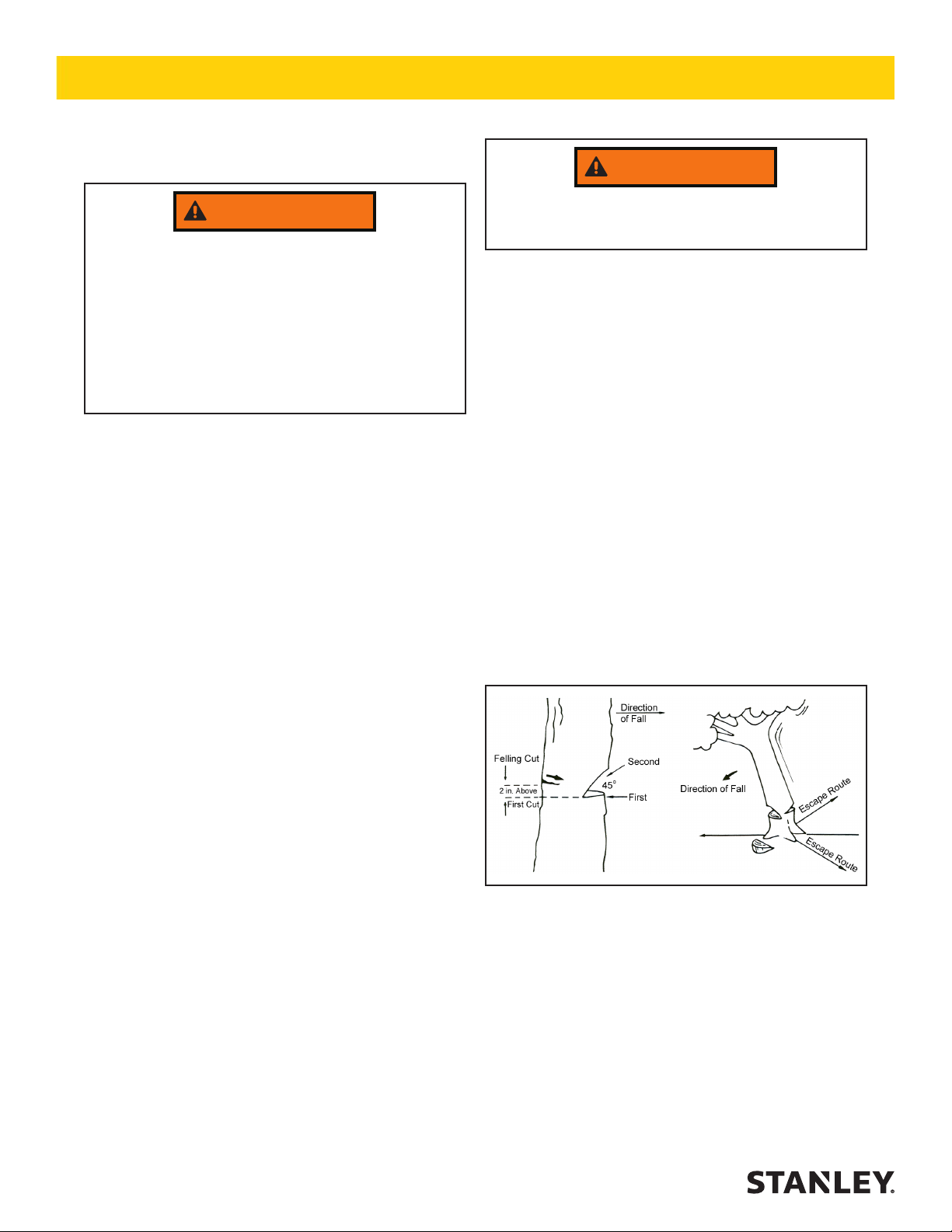
Watch for falling limbs.
4.
Make a diagonal cut down to meet the horizontal cut
and remove the wood from the notch.
FELLING OR BACK CUT
5. The felling or back cut is made on the side opposite
and at least 2 inches above the horizontal undercut
(the felling cut is made higher as the size of the tree
increases).
6. Start the cut horizontally parallel to the notch cut.
Cut until the saw is about 1 or 2 inches from the
notch. DO NOT CUT THROUGH THE NOTCH.
NOTE:
The uncut wood between the felling and notch cuts
is called the hinge. The hinge controls the fall of the
tree and should be of uniform thickness.
7. As the saw nears the back cut, watch the tree-top
and the cut for signs of movement. Be alert as soon
as the tree starts to move, turn off the saw, pull it
from the tree and move away quickly on your escape route.
FELLING OR TOPPING
1. Observe safety precautions.
NOTCHING OR UNDERCUTTING
2. The notching or undercutting cut is made on the side
you want the tree to fall.
3. Start the cut horizontally. Cut to about one-quarter of
the tree’s diameter.
14 ► CS25/28 User Manual
Figure 2. Felling a Tree
LOGS/LIMBS WITH PRESSURE ON
BOTTOM
1. Observe all safety precautions.
2. Begin with a bottom-cut. The depth of the cut should
be about one-third of the log diameter.
3. Finish with an upper cut, down from the top. The
saw cuts should meet.
Page 15

OPERATION
PRUNING & TRIMMING
1. Observe all safety precautions.
2. Use both hands. Keep a rm grip.
3. Be alert for kickback. Do not allow the tip of the bar
to touch anything while the chain is in motion.
Figure 3. Crosscutting Logs/Limbs with
Pressure on Bottom
4. Pole chain saws must be hung securely in a vertical
position to prevent dislodgement. Pole chain saws
must not be hung on utility wires or cables and must
not be left in the tree overnight. Pole chain saws
must be hung so the sharp edge is away from the
worker, if possible.
5. Warnings, when necessary, must be given by the
worker in the tree before a limb is dropped. “Timber” or “heads up” are common terms used for this
purpose.
6. A separate line should be attached to limbs that cannot be dropped safely or are too heavy to be controlled by hand. The line should be held by workers on the ground end of the rope. Use of the same
crotch for both the safety rope and the work rope
should be avoided.
7. The safety line or climbing rope must not be used for
any purpose but for climbing.
8. Cut branches must not be left in trees overnight.
TOPPING/LOWERING LIMBS
1. Observe all safety precautions.
2. Use both hands. Keep a rm grip.
3. Workers performing topping operations should
make sure the trees are able to stand the strain of
a topping procedure. If not, some other means of
lowering the branches should be provided, such as
a tree crane.
4. If large limbs are lowered in sections, the worker in
the tree should be above the limb being lowered.
5. Guidelines, hand lines, or tag lines must be used
when conditions warrant their use.
LIMBING AND BUCKING
1. Observe all safety precautions.
2. Use both hands. Keep a rm grip.
3. When it is possible to do so, the tree worker must
work on the side opposite the side on which the limb
is being cut.
4. Branches bent under tension must be considered
hazardous.
COLD WEATHER OPERATION
If the pole chain saw is to be used during cold weather,
preheat the hydraulic uid at low engine speed. When
using the normally recommended uids, uid should be
at or above 50 °F/10 °C (400 ssu/82 centistokes) before
use.
Damage to the hydraulic system or pole chain saw can
result from use with uid that is too viscous or thick.
Cutting frozen wood causes the cutters to wear, crack
and break at the back rivet hole unless proper precautions are taken. To extend chain life when cutting in cold
weather:
• Be sure the automatic oiler is working.
• Keep the chain tensioned and check often.
• Keep the chain properly sharpened. Touch up at
least every hour. Never force a dull chain to cut.
• Clean out the bar groove and keep the oil hole open.
Turn the bar over to equalize wear on the rails.
• Always install a new sprocket with a new chain.
CS25/28 User Manual ◄ 15
Page 16

OPERATION
AUTOMATIC OILER ADJUSTMENT
1. Observe all safety precautions.
2. The automatic oiler is located in the front of the motor housing. The oil volume can be adjusted with a
3/16 inch Allen wrench by turning the plug counterclockwise to increase output and turning clock wise
to decrease output.
NOTE:
Oil output varies proportionally to load and operat-
ing pressure. It should be adequate for most operations as adjusted from the factory.
3. Initial oiler adjustment is made with the saw bar and
chain removed.
The following step can be hazard ous. Failure to
heed the instructions could result in serious injury.
4. Connect the pole chain saw to a hydraulic power
source and check for proper operation. READ THE
FOLLOWING CAREFULLY BEFORE PROCEEDING.
a. Make sure the hydraulic power source is run-
ning at the lowest gpm/lpm rate it can while still
producing full pressure.
b. Secure the pole chain saw rmly in a bench vise
and place the correct size wrench on the 1/2-20
nut securing the sprocket.
c. Connect the hydraulic power source to the pole
chain saw and turn the circuit control valve to
the ON position.
d. With a rm grip on the pole chain saw and
wrench, SLOWLY squeeze the trigger to activate it.
e. Adjust the oiler for a ow of approximately one
drop every one to two seconds.
f. Release the trigger and remove the wrench.
CHAIN TENSION ADJUSTMENT
1. Observe all safety precautions.
2. When the chain appears loose, lubricate it well and
let it cool for a few minutes to allow for contraction
of the chain. Disconnect the pole chain saw from its
hydraulic power source.
NOTE:
Perform Steps 3 through 6 while holding the top end
of the saw bar upward.
3. Loosen the two saw bar nuts slightly.
4. Tighten the chain tension screw until the bot toms of
the tie straps and cutters just touch the saw bar rails
of the bottom of the saw bar.
5. Pull the chain around the saw bar by hand to be sure
it ts the sprocket and saw bar properly. The chain
should move easily.
6. Hold the saw bar tip up as you tighten the two saw
bar nuts.
7. Connect the pole chain saw to a hydraulic power
source. Operate the chain at low speed (gpm) for a
minute or two while pumping extra oil on the chain.
8. Stop the pole chain saw and check the tension.
If it has loosened, disconnect the pole chain saw
from the hydraulic power source and perform Steps
3 through 6 again to tighten the chain to the correct
tension.
9. Reconnect the pole chain saw to the hydraulic power source. Operate the saw and make a few easy
cuts. Check chain tension and readjust if necessary
(disconnect it from the hydraulic power source and
perform Steps 3 through 6).
NOTE:
Never break in a new chain under a heavy cutting
load.
10. Watch the chain tension carefully for the rst half-
hour of cutting.
16 ► CS25/28 User Manual
Page 17

NOTICE
TOOL PROTECTION & CARE
In addition to the Safety Precautions found in
this manual, observe the following for equipment
protection and care.
• Make sure all couplers are wiped clean before connection.
• The hydraulic circuit control valve must be in the
OFF position when coupling or uncoupling hydraulic
tools. Failure to do so may result in damage to the
quick couples and cause overheating of the hydraulic system.
• Always store the tool in a clean dry space, safe from
damage or pilferage.
• Make sure the circuit PRESSURE hose (with male
quick disconnect) is connected to the IN port. The
circuit RETURN hose (with female quick disconnect)
is connected to the opposite port. Do not reverse cir-
cuit ow. This can cause damage to internal seals.
• Always replace hoses, couplings and other parts
with replacement parts recommended by Stanley
Hydraulic Tools. Supply hoses must have a minimum working pressure rating of 2500 psi/172 bar.
• Do not exceed the rated ow (see Specications) in
this manual for correct ow rate and model number.
Rapid failure of the internal seals may result.
• Always keep critical tool markings, such as warning
stickers and tags legible.
• Do not use the tool for applications it was not designed for. The chain saw is intended to cut wood
only.
• Keep chain sharp for maximum tool performance.
• Tool repair should be performed by experienced
personnel only.
• Make certain that the recommended relief valves
are installed in the pressure side of the system.
• Do not use the tool for applications for which it was
not intended.
CS25/28 User Manual ◄ 17
Page 18

TROUBLESHOOTING
If symptoms of poor performance develop, the following chart can be used as a guide to correct the problem.
When diagnosing faults in operation of the pole chain saw, always make sure the hydraulic power source is supply-
ing the correct hydraulic ow and pressure as listed in the table. Use a owmeter know to be accurate. Check the
ow with the hydraulic uid temperature at least 80 °F/27 °C.
PROBLEM CAUSE SOLUTION
Cuts slow. Insufcient uid ow or low relief
valve setting.
Chain dull. Sharpen per instructions or replace.
Back-pressure too high. Should not exceed 250 psi/17 bar at
Bar turns color. Insufcient oiler ow. Adjust oiler per service instructions.
Tool does not run. Power unit not functioning. Check power unit for proper ow and
Coupler or hoses blocked. Remove obstruction.
Mechanical failure. Disassemble tool and inspect for
Tool runs backwards. Pressure and return hoses reversed. Correct for proper ow direction.
Oil leakage around drive
sprocket.
On/Off trigger is hard to press. Pressure and return hoses reversed. Correct for proper ow direction.
Motor sections oil leakage. Motor face seal failure. Replace as required.
Motor shaft seal failure. Replace as required. Make sure that
Back-pressure too high. Should not exceed 250 psi/17 bar at
Adjust uid ow to proper gpm. For
optimum performance adjust relief
valve to 2250 psi/155 bar.
rated ow measured at the end of the
tool operating hoses.
pressure 4–6 gpm/15–22 lpm at 1500
psi/104 bar minimum for CS28. 7–9
gpm/26–34 lpm at 1000 psi/70 bar
minimum for the CS25.
damage.
Motor shaft rotates clockwise.
oil present is not the result of excess
oiler ow.
rated ow measured at the end of the
tool operating hoses.
18 ► CS25/28 User Manual
Page 19

SPECIFICATIONS
Capacity
CS25 and CS28 .................................................................................... 12 and 15 inch/30 and 38 cm Cut Lengths
Weight (w/o Bar and Chain) ......................................................................................................................8.5 lbs/4 kg
Overall Length
10 inch Bar ...................................................................................................................................75 inches/190 cm
12 inch Bar ..................................................................................................................................90 inches/229 cm
15 inch Bar ...................................................................................................................................92 inches/234 cm
Pressure
CS25 ........................................................................................................................... 1500–2000 psi/105–140 bar
CS28 ............................................................................................................................. 1000–2000 psi/70–140 bar
Flow Range
CS25 ........................................................................................................................................ 4–6 gpm/15–22 lpm
CS28 ........................................................................................................................................ 7–9 gpm/26–34 lpm
Optimum Flow
CS25 .................................................................................................................................................. 5 gpm/19 lpm
CS28 .................................................................................................................................................. 8 gpm/30 lpm
Porting ...................................................................................................................................-8 (1/2 inch) SAE O-ring
Connect Size and Type ....................................................................................................................Adapter w/ Male
Hose Whips ........................................................................................................................................................... No
SOUND AND VIBRATION DECLARATION
Test conducted on CS2881101, S/N 112 operated at standard 8 gpm input
Measured A-weighted sound power level, Lwa (ref. 1pW) in decibels 106 dBA
Uncertainty, Kwa, in decibels 3 dBA
Measured A-weighted sound pressure level, Lpa (ref. 20 µPa) at operator’s position, in decibels 98 dBA
Uncertainty, Kpa, in decibels 3 dBA
Values determined according to noise test code given in ISO 15744, using the basic standard ISO
3744
NOTE: The sum of a measured noise emission value and its associated uncertainty represents an
upper boundary of the range of values which is likely to occur in measurements.
Declared vibration emission value in accordance with EN 12096
Measured vibration emission value: Trigger hand 1.1 m/sec²
Measured vibration emission value: Assist hand 3.9 m/sec²
Uncertainty: K .5 m/sec²
Values determined according to ISO 8662-1, ISO 5349-1,2
ACCESSORIES
Description Part Number
12 inch/30 cm Saw Bar......................................................................................................................................08347
15 inch/38 cm Saw Bar......................................................................................................................................07638
Saw Chain for 12 inch/30 cm Bar 34SL (56 Drive Links) ..................................................................................08348
Saw Chain for 15 inch/38 cm Bar 34SL (64 Drive Links) ..................................................................................07641
Sprocket 7T, .325 Pitch...................................................................................................................................... 07629
Chain Guard for 18 inch/46 cm Bar Length ....................................................................................................... 05144
Flat File .............................................................................................................................................................. 11294
Scrench ............................................................................................................................................................. 11464
SERVICE TOOLS
O-ring Tool Kit .................................................................................................................................................... 04337
CS25/28 User Manual ◄ 19
Page 20

CS25 / CS28 PARTS ILLUSTRATION
To order complete motor assembly
see “Note” on parts list (Page 21).
20 ► CS25/28 User Manual
Page 21

CS25 / CS28 PARTS LIST
PART
ITEM
NO. QTY DESCRIPTION
1 19212 1 CAPSCREW
2 65834 1 CHAIN GUARD
3 07631 2 NUT
4 08348 1 SAW CHAIN – 12 INCH
07641 1 SAW CHAIN – 15 INCH
5 66577 1 CHAIN GUIDE PLATE
6 07630 2 STUD
7 07620 1 BAR ADJUSTMENT NUT
8 07632 1 SCREW
9 04044 2 NEEDLE ROLLER
10 04106 2 DRIVER GEAR (8 GPM)
07832 2 DRIVER GEAR (5 GPM)
11 — — NO ITEM
12 07652 1 REAR GEAR HOUSING ASSY (8 GPM)
07834 1 REAR GEAR HOUSING ASSY (5 GPM)
13 00753 8 CAPSCREW
14 04041 4 BUSHING
15 — — NO ITEM
16 07612 1 IDLER SHAFT
17 00020 1 O-RING*
18 66201 1 MOTOR HOUSING SERVICE ASSY
19 16668 4 O-RING*
20 00453 1 NUT
21 07617 1 WASHER
22 07629 1 RIM SPROCKET
23 07616 1 SPROCKET ADAPTER
24 06635 1 RETAINING RING
25 00335 1 BEARING
26 04856 1 RETAINING RING
27 07615 1 SEAL BACK-UP WASHER
28 04037 1 SEAL*
29 60975 1 MOTOR SHAFT
30 65839 1 NAME TAG – CS25
65840 1 NAME TAG – CS28
31 18089 6 CAPSCREW
32 65937 1 OUTER TUBE ASSY – CS258X1
65936 1 OUTER TUBE ASSY – CS258X2
60973 1 OUTER TUBE ASSY – CS288X1
62237 1 OUTER TUBE ASSY – CS288X2
33 00042 2 OIL TUBE ASSY – CS2X8X1
62238 2 OIL TUBE ASSY – CS2X8X2
34 NA 1 DIELECTRIC TEST DECAL
35 15863 1 WARNING DECAL
36 05153 1 STANLEY DECAL
37 03786 1 7-9 GPM DECAL
PART
ITEM
NO. QTY DESCRIPTION
03782 1 4-6 GPM DECAL
39 12412 1 ELECTRIC WARNING DECAL
40 24833 1 HANDLE ASSY (NOTE: DOES NOT
41 07627 1 O-RING*
42 19868 1 SPRING
43 51183 1 TRIGGER
44 01534 1 ROLL PIN
45 51182 1 TRIGGER GUARD
46 22147 2 CAPSCREW
47 00936 2 ADAPTER
48 01605 2 O-RING*
49 07626 1 O-RING*
50 19874 1 VALVE SPOOL
51 00026 1 O-RING*
52 19875 1 SELECTOR SPOOL
53 16070 1 RETAINING RING*
54 26414 1 LOCK OUT KIT
55 08347 1 SAW BAR – 12 IN
07638 1 SAW BAR – 15 IN
56 02921 1 AUTOMATIC OILER
57 01362 1 O-RING*
58 06971 1 LOCK NUT
59 02634 2 WASHER
60 66578 1 CHAIN GUIDE
61 04746 1 AUTOMATIC OILER DECAL
62 34685 1 SOUND POWER LEVEL DECAL
63 11206 1 CIRCUIT TYPE C DECAL (CE ONLY)
11207 1 CIRCUIT TYPE D DECAL (CE ONLY)
64 28323 1 CE DECAL (CE ONLY)
65 28409 1 COMPOSITE SAFETY DECAL
03693 1 CLOSED-CENTER DECAL
21053 1 SEAL KIT
COME WITH SPOOL OR O-RING)
(CE ONLY)
(CE ONLY)
(NOT ILLUSTRATED)
* Denotes Part in Seal Kit
Note: To order the full motor assembly which includes
the following items: 6 thru 29 and 56 thru 58.
CS25 Motor Assembly (5-GPM) P/N-73196
CS28 Motor Assembly (8-GPM) P/N-73195
CS25/28 User Manual ◄ 21
Page 22

Stanley Hydraulic Tools
3810 SE Naef Road
Milwaukie, Oregon 97267-5698 USA
(503) 659-5660 / Fax (503) 652-1780
www.stanleyhydraulics.com
 Loading...