

DW080LRS, DW080LGS
Rotary Laser
Laser rotatif
Láser rotativo
Laser Rotativo
Instruction Manual
Guide d’utilisation
Manual de instrucciones
Manual de Instruções
If you have questions or comments, contact us.
Pour toute question ou tout commentaire, nous contacter.
Si tiene dudas o comentarios, contáctenos.
Dúvidas? Visite-nos na Internet em www.D
eWALT.com.br
1-800-4-DeWALT

English 8
Français 18
Español 29
Português 41
A
15
10
11
12
2
3 618
9
14
13
25
24
745
1
B
5
X
Y
3
RPM
˚/45˚/90˚
15
4
2
6
7
3
C
20
20
5/8-11"
5/8-11"
PLUMB MODE/MODE APLOMB /MODALIDAD DE PLOMADA/
MODO NIVELAMENTO VERTICAL
LEVEL MODE/MODE NIVEAU/MODALIDAD DE NIVEL/
D
PLUMB MODE
MODE APLOMB
MODALIDAD DE
PLOMADAL
MODO NIVELAMENTO
VERTICAL
E F
15
MODO DE NIVELAMENTO
LEVEL MODE
MODE NIVEAU
MODALIDAD DE
NIVEL
MODO DE
NIVELAMENTO
4
G
H
21
I
28
54
53
27
26
22
22
30
30
23
J
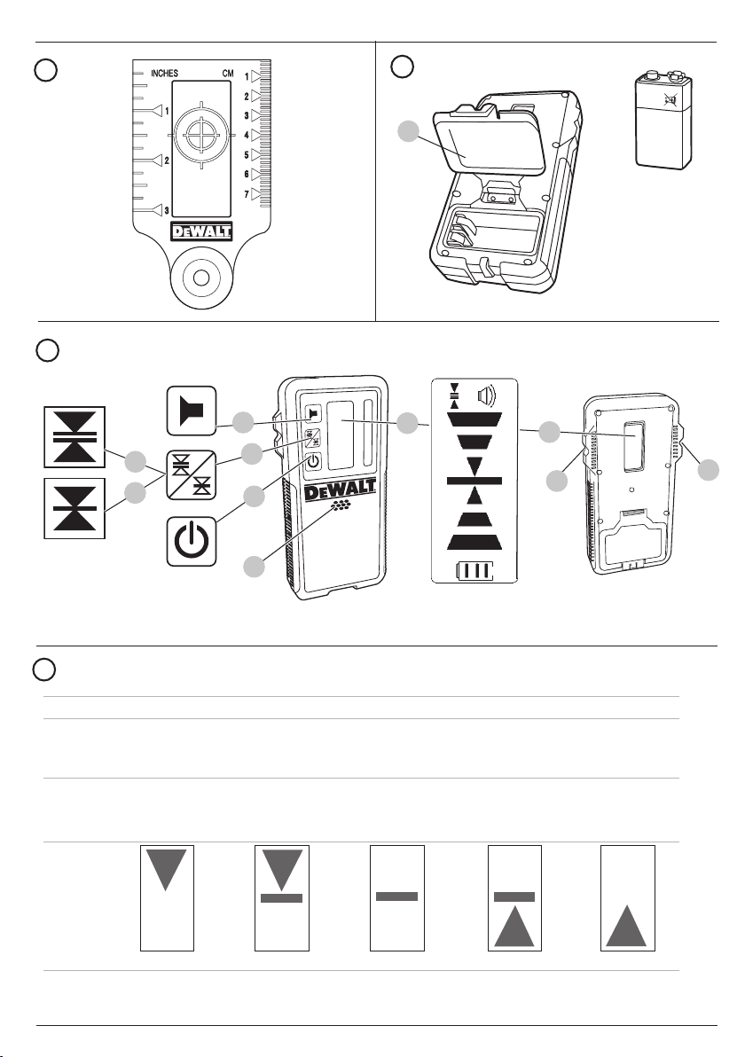
INDICATORS/INDICATEURS /INDICADORES/INDICADORES
Above Grade/
Au-dessus du niveau /
Por encima del nivel
Acima do grau
fast beep /
bip rapide /
bip rápido/
sinais audíveis
signal sonore /
audible signals/
señales auditivas/
ícones da tela
display icons/
icône affichée /
íconos en pantalla/
Bipe rápido
Slightly Above Grade/
Légèrement au-dessus du niveau /
Ligeramente por encima del nivel/
Ligeiramente acima do grau
fast beep /
bip rapide /
bip rápido/
Bipe rápido
On Grade/
Au niveau /
En nivel/
Um grau
steady tone/
tonalité constante /
tono constante/
Tom estável
Slightly below Grade/
Légèrement au-dessous du niveau /
Ligeramente por debajo del nive/
Ligeiramente abaixo do graul
slow beep/
bip lent /
bip lento/
Bipe lento
Below Grade/
Au-dessous du niveau /
Por debajo del nivel/
Abaixo do grau
slow beep/
bip lent /
bip lento/
Bipe lento
5
K
33
47
32
L
M
42
41
45
39
37
46
42
40
44
45
40
44
46
43
N
6

O
BEAM
FAISCEAU
RAYO
RAIO
A
B
L
P
LASER UNIT ROTATED 180˚
ROTATION DE L’APPAREIL LASER A 180˚
UNIDAD LÁSER ROTADA EN 180º
UNIDADE DE LASER EM ROTAÇÃO DE 180º
BEAM
FAISCEAU
RAYO
RAIO
AA
L
Q R
Marks on walls
Reperes sur les murs
Marcas en la pared
Marcas na parede
BB
7

ENGLISH
Definitions: Safety Alert Symbols and Words
This instruction manual uses the following safety alert symbols and words to alert you to hazardous situations and your risk of
personal injury or property damage.
DANGER: Indicates an imminently hazardous situation which, if not avoided, will result in death or serious injury.
WARNING: Indicates a potentially hazardous situation which, if not avoided, could result in death or serious injury.
CAUTION: Indicates a potentially hazardous situation which, if not avoided, may result in minor or moderate injury.
(Used without word) Indicates a safety related message.
NOTICE: Indicates a practice not related to personal injury which, if not avoided, may result in property damage.
If you have any questions or comments about this or any DeWALT tool, call us toll free at: 1-800-4-DeWALT
(1-800-433-9258).
Warning: To reduce the risk of injury, user must read instruction manual.
Safety Instructions for Lasers
WARNING! Read and understand all instructions. Failure to follow all instructions listed
below may result in electric shock, fire and/or serious personal injury.
SAVE ALL WARNINGS AND INSTRUCTIONS FOR FUTURE REFERENCE
WARNING! Laser Radiation Exposure. Do not disassemble or modify the laser level. There are no user serviceable
parts inside. Serious eye injury could result.
WARNING: Hazardous Radiation. Use of controls or adjustments or performance of procedures other than those
specified herein may result in hazardous radiation exposure.
• Do not operate the laser in explosive atmospheres, such as in the presence of flammable liquids, gases, or dust.
Power tools create sparks which may ignite the dust or fumes.
• Use the laser only with the specifically designated batteries. Use of any other batteries may create a risk of fire.
• Store idle laser out of reach of children and other untrained persons. Lasers are dangerous in the hands of untrained
users.
• Use only accessories that are recommended by the manufacturer for your model. Accessories that may be suitable for
one laser, may create a risk of injury when used on another laser.
• Tool service must be performed only by qualified repair personnel. Service or maintenance performed by unqualified
personnel may result in injury. To locate your nearest
to http://www.DeWALT.com on the Internet.
• Do not use optical tools such as a telescope or transit to view the laser beam. Serious eye injury could result.
• Do not place the laser in a position which may cause anyone to intentionally or unintentionally stare into the laser
beam. Serious eye injury could result.
• Turn the laser off when it is not in use. Leaving the laser on increases the risk of staring into the laser beam.
• Do not position the laser near a reflective surface which may reflect the laser beam toward anyone’s eyes. Serious eye
injury could result.
• Do not operate the laser around children or allow children to operate the laser. Serious eye injury may result.
• Do not remove or deface warning labels. Removing labels increases the risk of exposure to radiation.
• Position the laser securely on a level surface. Damage to the laser or serious injury could result if the laser falls.
WARNING: Use of controls or adjustments or performance of procedures other than those specified herein may result in
hazardous radiation exposure.
WARNING! DO NOT DISASSEMBLE THE ROTARY LASER. There are no user serviceable parts inside.
Disassembling the rotary laser will void all warranties on the product. Do not modify the product in any way.
Modifying the tool may result in hazardous laser radiation exposure.
DeWALT service center call 1–800–4-DeWALT (1–800–433–9258) or go
8

• The label on your tool may include the following symbols.
V ........................volts
mW ....................milliwatts
........laser warning symbol
Warning Labels
For your convenience and safety, the following label is on your laser.
WARNING: To reduce the risk of injury, user must read instruction manual.
WARNING: LASER RADIATION. DO NOT STARE INTO BEAM. Class 3R Laser Product
AVOID EXPOSURE -LASER RADIATION IS EMITTED FROM THIS APERTURE
ENGLISH
nm..........wavelength in nanometers
3R .......... Class 3R Laser
DW080LGS
DW080LRS
Laser Information
The DW08
except for deviations pursuant to laser notice No. 50, dated June 24, 2007.
These devices comply with Part 15 of the FCC Rules. Operation is subject to the following two conditions: 1) this device may
not cause harmful interference, and 2) this device must accept any interference received, including interference that may cause
undesired operation.
NOTE: This equipment has been tested and found to comply with the limits for a Class B digital device, pursuant to Part 15 of the
FCC Rules. These limits are designed to provide reasonable protection against harmful interference in a residential installation.
This equipment generates, uses and can radiate radio frequency energy and, if not installed and used in accordance with the
instructions, may cause harmful interference to radio communications. However, there is no guarantee that interference will not
occur in a particular installation. If this equipment does cause harmful interference to radio and television reception, which can be
determined by turning the equipment off and on, the user is encouraged to try to correct the interference by one or more of the
following measures:
• Reorient or relocate the receiving antenna.
0LRS/LGS Cordless Rotary Laser is a CLASS 3R laser product and complies with 21 CFR 1040.10 and 1040.11
Conforms to UL STDS 61010-1 & 2595
Certified to CSA STD C22.2 No. 61010-1
Complies with IEC 60825-1:2014
9

ENGLISH
• Increase the separation between the equipment and
receiver.
• Connect the equipment into an outlet on a circuit
differentfrom that which the receiver is connected.
• Consult the dealer or an experienced radio/TV technician
for help.
Canada, Industry Canada (IC) Notices
Class B digital circuitry of this device complies with Canadian
ICES-003. This device complies with Industry Canada licenseexempt RSS standard(s). Operation is subject to the following
two conditions: 1) this device may not cause interference,
and 2) this device must accept any interference, including
interference that may cause undesired operation of the device.
READ ALL INSTRUCTIONS
Batteries and Power
This DeWALT rotary laser will accept all DeWALT 20 volt
lithium ion batteries, but is built to best resist damage during a
fall when used with the following batteries: All 1.5Ah and 2Ah
DeWALT 20 volt lithium ion batteries.
Charging the Battery
The battery pack is not fully charged out of the carton. You
need to use a DeWALT 20 volt charger to charge the battery
pack before you can use the rotary laser.
• Refer to the chart at the end of this manual for compatibility
of chargers and battery packs.
• Be sure to read all safety instructions before using your
charger.
WARNING:
• DO NOT attempt to charge the battery pack
1. Slide the battery pack into the charger as described in the
2. Wait until the battery pack is fully charged.
3. Slide the battery pack out of the track.
NOTE: When ordering replacement battery packs, be sure to
include the catalog number and voltage.
with any chargers other than the ones listed
in this manual. The charger and battery pack are
specifically designed to work together.
• Carefully follow all instructions and warnings on
the battery label and package and accompanying
Battery Safety Manual.
Battery Safety Manual.
3. Slide the battery pack all the way into the track on the side
of the laser.
4. Release the button on the battery pack.
Removing the Battery Pack
1. Press and hold the release button on the battery pack.
2. Slide the battery pack out of the track on the laser.
3. Release the button on the battery pack.
4. To recharge the battery pack, insert it into the charger, as
described in the Battery Safety Manual.
WARNING: Batteries can explode or leak, and can
cause injury or fire. To reduce this risk, follow the
instructions in the Battery Safety Manual.
Storing Battery Packs
• The best storage place is one that is cool and dry, and
away from direct sunlight and excess heat or cold.
• Long storage will not harm the battery pack or charger.
Under proper conditions, they can be stored for 5 years
or more.
SAVE THESE INSTRUCTIONS FOR FUTURE USE
User Safety
Personal Safety
• Stay alert, watch what you are doing, and use common
sense when operating a laser product. Do not use
the tool while tired or under the influence of drugs,
alcohol, or medication. A moment of inattention while
operating laser products may result in serious personal
injury.
• Use appropriate personal protective equipment,
including eye protection when working in a construction
environment.
Tool Use and Care
• Do not use the tool if the switch does not turn it on or
off. Any tool that cannot be controlled with the switch is
dangerous and must be repaired.
• Store idle laser products out of the reach of children
and do not allow persons unfamiliar with the laser
product or these instructions to operate the laser
product. Laser products are dangerous in the hands of
untrained users.
• Use only accessories that are recommended by the
manufacturer for your model. Accessories that may be
suitable for one tool, may become hazardous when used
with another tool.
Installing the 20V DeWALT Battery Pack
1. Position the fully-charged 20V DeWALT battery pack so the
release button (Figure
to the right.
2. Press and hold down the release button on the battery
pack.
E
15
) is facing away from you and
10

Caution:
This device complies with Part 15 of the FCC Rules / Industry
Canada licence-exempt RSS standard(s). Operation is subject to
the following two conditions: (1) this device may not cause harmful
interference, and (2) this device must accept any interference
received, including interference that may cause undesired
operation.
Le présent appareil est conforme aux CNR d'Industrie Canada
applicables aux appareils radio exempts de licence. L'exploitation
est autorisée aux deux conditions suivantes : (1) l'appareil ne doit
pas produire de brouillage, et (2) l'utilisateur de l'appareil doit
accepter tout brouillage radioélectrique subi, même si le brouillage
est susceptible d'en compromettre le fonctionnement.
Changes or modifications not expressly approved by the party
responsible for compliance could void the user's authority to
operate the equipment.
This equipment has been tested and found to comply with the
limits for a Class B digital device, pursuant to part 15 of the FCC
Rules. These limits are designed to provide reasonable protection
against harmful interference in a residential installation. This
equipment generates uses and can radiate radio frequency
energy and, if not installed and used in accordance with the
instructions, may cause harmful interference to radio
communications. However, there is no guarantee that interference
will not occur in a particular installation. If this equipment does
cause harmful interference to radio or television reception, which
can be determined by turning the equipment off and on, the user
is encouraged to try to correct the interference by one or more of
the following measures:
—Reorient or relocate the receiving antenna.
—Increase the separation between the equipment and receiver.
—Connect the equipment into an outlet on a circuit different from
that to which the receiver is connected.
—Consult the dealer or an experienced radio/TV technician for
help.
MPE Reminding
To satisfy FCC / IC RF exposure requirements, a separation
distance of 20 cm or more should be maintained between the
antenna of this device and persons during device operation.
To ensure compliance, operations at closer than this distance is
not recommended.
L'antenne installée doit être située
de facon à ce que la population ne puissey être exposée à une dis
tance de moin
de 20 cm. Installer l'antenne de facon à ce que le personnel ne
puisse approcher à 20 cm ou moins de la position centrale de l’
antenne.
La FCC des éltats-unis stipule que cet appareil doit être en tout
temps éloigné d’au
moins 20 cm des personnes pendant son functionnement.
11

The RBRC® Seal
15˚/45˚/90˚
The RBRC® (Rechargeable Battery
Recycling Corporation) Seal on the nickel
cadmium, nickel metal hydride or lithium-ion
batteries (or battery packs) indicates that the
costs to recycle these batteries (or battery
packs) at the end of their useful life have already been paid
DeWALT. In some areas, it is illegal to place spent nickel
by
cadmium, nickel metal hydride or lithium-ion batteries in the
trash or municipal solid waste stream and the Call 2 Recycle®
program provides an environmentally conscious alternative.
Call 2 Recycle, Inc., in cooperation with
battery users, has established the program in the United
States and Canada to facilitate the collection of spent nickel
cadmium, nickel metal hydride or lithium-ion batteries. Help
protect our environment and conserve natural resources by
returning the spent nickel cadmium, nickel metal hydride or
lithium-ion batteries to an authorized
or to your local retailer for recycling. You may also contact
your local recycling center for information on where to drop off
the spent battery. RBRC® is a registered trademark of Call 2
Recycle, Inc.
DeWALT and other
DeWALT service center
Operation
Operating Tips
• To extend battery life per charge, turn the laser off when it
is not in use.
• To ensure the accuracy of your work, check the laser
calibration often. Refer to Calibrating the Laser.
• Before attempting to use the laser, make sure the tool is
positioned on a relatively smooth, secure surface.
• Always mark the center of the laser line or dot. If you
mark different parts of the beam at different times you will
introduce error into your measurements.
• To increase working distance and accuracy, set up the
laser in the middle of your working area.
• When attaching to a tripod or wall, mount the laser
securely.
• When working indoors, a slow rotary head speed will
produce a visibly brighter line, a faster rotary head speed
will produce a visibly solid line.
• To increase beam visibility, wear Laser Enhancement
Glass es and/or use a Laser Target Card to help find the
beam.
• Extreme temperature changes can cause movement or
shifting of building structures, metal tripods, equipment,
etc., which can effect accuracy. Check your accuracy often
while working.
• When working with the
the laser’s rotation speed to the fastest setting.
• If the laser is dropped or has suffers a sharp blow, have
the calibration system checked by a qualified service
center before using the laser.
DeWALT Digital Laser Detector, set
ENGLISH
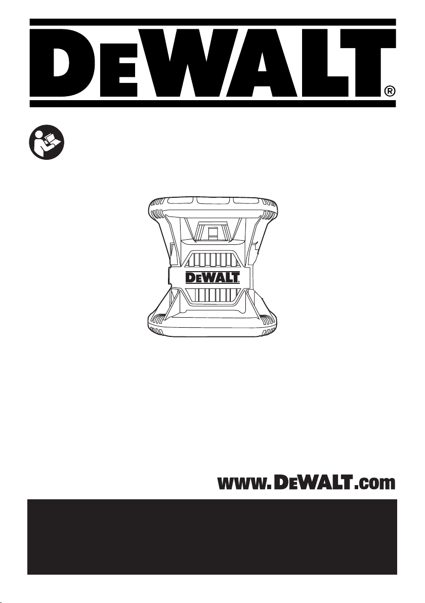
Control Panel (Fig. A)
2
6
and
again.
1
, the
7
.
2
.
The laser is primarily controlled by the power button
mode button
4
. These features are then modified when used with either the
Axis selection button
or the two direction/elevation adjustment buttons
The direction/elevation adjustment buttons control the rotational
direction of the laser head as well as adjust the elevation of the
beam when the unit is in slope mode. These buttons can also
be used to incrementally rotate the beam when the unit is in
Scan mode.
The buttons on the DW080LRS/DW080LGS control panel and
the DW080LRS/DW080LGS Remote keypad work the same,
unless otherwise indicated.
2
, the speed button
5
(DW080LRS/LGS in Slope mode only),
3
and the scan mode button
Power Button
The Power button is used to turn the laser unit on and off.
• To power ON the DW080LRS/LGS laser unit, press the
Power button once.
• To completely power OFF the DW080
unit, press the power button for 3 sec.
LRS/LGS laser
Speed/Rotation Button
The speed button
laser beam through its 4 preset speeds (150, 300, 600, and
1200 RPM).
3
is used to adjust the rotation speed of the
Scan Mode Button
The scan mode button
sweep back and forth, creating a short, bright laser line. This
short line is much brighter and more visible than when the unit
is in full rotation mode.
Using Scan Mode
• To enter Scan Mode, push and release the scan mode
• The direction of the scan zone can be controlled with the
4
button
press the button until you reach the desired angle.
arrow buttons
4
is used to make the laser head
. To cycle through the scan angles, continue to
6
7
and
.
Slope Mode Button
• To activate Slope Mode press the slope mode button
• To return to self-leveling mode and re-engage full self-
leveling, press and hold the mode button
Setting the Slope Direction
When Slope Mode is activated, the unit automatically engages
the X- Axis. This allows you to slope the laser in the direction of
the X-Axis, as indicated by the “gunsights” on the rollcage.
11
The LED light
In certain situations, it may be desirable to slope the laser in
the Y-axis. The direction of Slope Mode can be changed back
and forth between the Y-axis and the X-axis by pressing the
X-Y axis button
24
25
or
.
12
or
indicates the current slope direction.
5
. The selected axis is identified by LED light
12

ENGLISH
Setting the Amount of Slope
1. Turn on Slope Mode.
2. Select the desired axis.
6
3. Use the Arrow buttons (Fig.
B
7
,
and
) to tilt the laser
rotor head up and down.
A
Arrow Buttons (Fig.
The arrow buttons (Figure
R
,
)
A
6
7
and
) are used for different
functions depending on the operating mode of the laser unit.
• In Self-Leveling Horizontal Mode, the arrow buttons
rotate the direction of the laser beam clockwise or counterclockwise during rotation, or adjust the position of the laser
beam clockwise or counter-clockwise during Scan Mode.
• In Self-Leveling Vertical Mode, the arrow buttons rotate
the direction of the laser beam clockwise or counterclockwise during rotation, or adjust the position of the laser
beam clockwise or counter-clockwise during Scan Mode.
• In Slope Mode, the arrow buttons are used to tilt the
laser head.
Connection Buttons
A
10
The connection buttons (Figure
13
and
) provide
different ways to wirelessly connect to the laser.
A
• Press the radio waves button
(Figure
10
) to
connect your cell phone to the Detector which is connected
to the laser.
• Press the Bluetooth button
(Figure A
13
) to enable
Bluetooth on the laser. If the laser is within 100 ft (30 m),
you can use the Tool Connect application on your
cell phone to control the laser, instead of using the remote.
Also, if the laser is dropped, disturbed, etc., it will send
messages to the Tool Connect application to inform you.
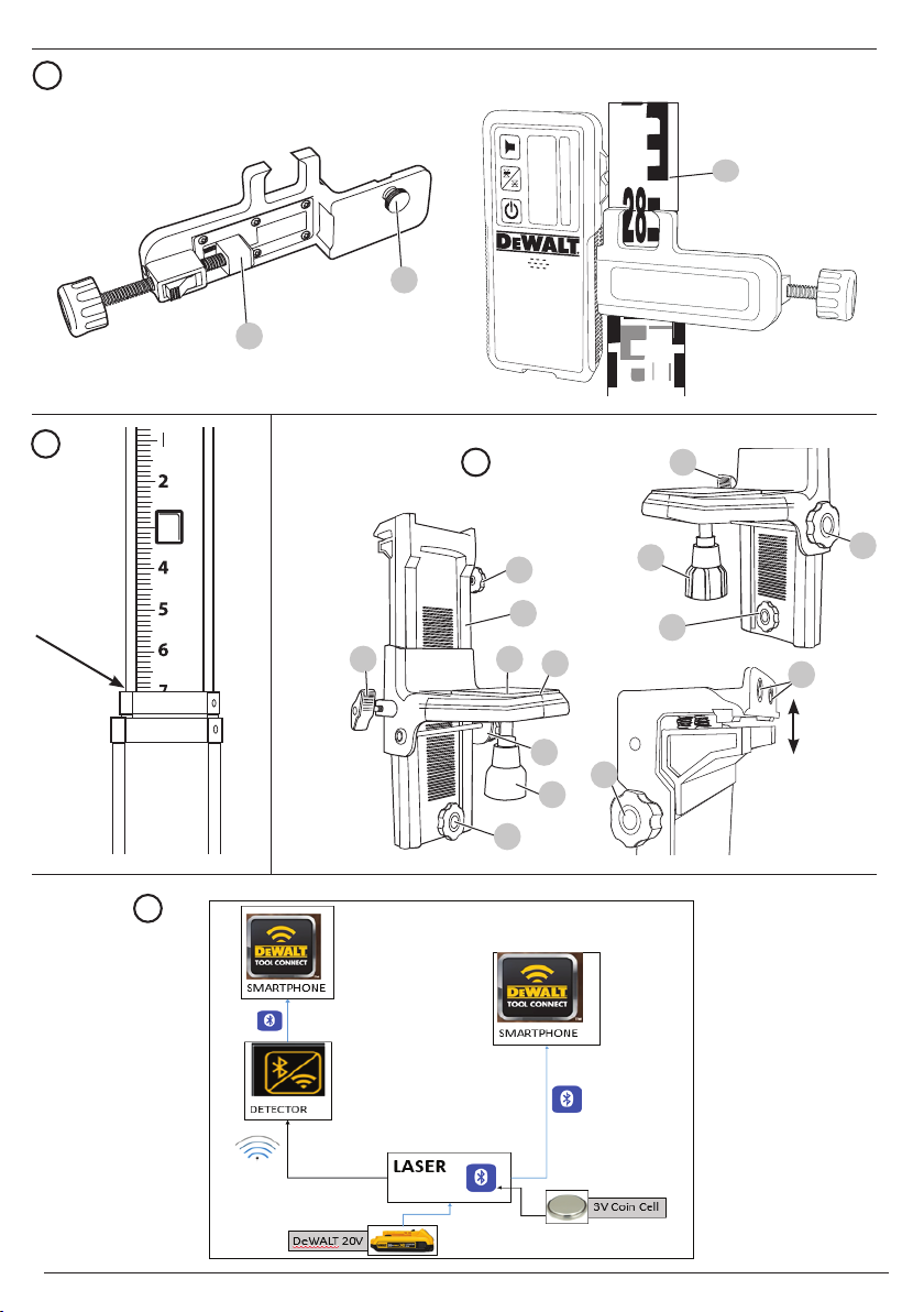
Using the Tool Connect Application
You can use Bluetooth® capability to pair the laser with the
DEWALT® Tool Connect application on your cell phone, and then
use your cell phone to control the laser (Figure N).
1. From either
®
Tool Connect application to your cell phone.
DEWALT
2. On the laser keypad, press
3. On the laser keypad, press to turn on Bluetooth
Bluetooth does not turn on, replace the coin cell battery (3V
CR2430) on the bottom of the laser.)
4. Using the DEWALT® Tool Connect application, select the
product type (Rotary Laser) and pair your cell phone to the
DW080LRS/DW080LGS.
or , download the
to turn the laser on.
®. (
If
When the laser is on, the DEWALT® Tool Connect application will
display information about the laser:
• A laser safety icon to let you know the laser is on.
• The laser's current settings for RPM, Slope, etc.
• If the current settings are one of the "favorite settings" you
have saved for the laser, it will display the name of that
setting (e.g., Main St - Site 1).
• If the Tracking feature is on, the application will know
where the laser is and will let you know if the laser has
been taken and is now out-of-range.
THE BLUETOOTH® WORD MARK AND LOGOS ARE REGISTERED TRADEMARKS OWNED
BY BLUETOOTH SIG, INC. AND ANY USE OF SUCH MARKS BY STANLEY TOOLS IS UNDER
LICENSE. APPLE AND THE APPLE LOGO ARE TRADEMARKS OF APPLE INC., REGISTERED
IN THE U.S. AND OTHER COUNTRIES. APP STORE IS A SERVICE MARK OF APPLE INC.,
REGISTERED IN THE U.S. AND OTHER COUNTRIES. GOOGLE PLAY AND THE GOOGLE PLAY
LOGO ARE TRADEMARKS OF GOOGLE INC.
Turning the Laser On (Fig. E, B)
1. Insert the fully charged 20V battery pack as shown in
Figure E.-
2. Gently press the power button
- The power LED indicator light (Figure
to power ON the laser.
A
9
) will
illuminate.
- Self-leveling mode is activated automatically and the
laser unit will self-level. Once the laser unit is level, the
beam will rotate clockwise once at 600 RPM.
- After 10 sec., Hi Mode (Anti- Drift) is activated
A
automatically and the Hi LED (Figure
8
) will
illuminate.
A
3. Press the speed/rotation button (Figure
3
) to adjust the
rotation speed. The direction can be changed using buttons
6
7
and
.
A
4. Press the Scan button (Figure
4
) to set the laser to
scan in 0°, 15°, 45°, or 90° degree mode.
A
12
If you turn ON Slope Mode, the Slope LED (Figure
)
will light. If using X-axis leveling, the X-axis LED (Figure A
24
) will light, or if using Y-axis leveling, the Y-axis LED (Figure
A
25
) will light instead.
Calibrating the Laser (Fig. O, P)
Field calibration checks should be done frequently. This section
provides instructions for performing simple field calibration
checks of your DeWALT Rotary Laser. Field calibration checks
do not calibrate the laser. That is, these checks do not correct
errors in the leveling or plumbing capability of the laser. Instead,
the checks indicate whether or not the laser is providing a
correct level and plumb line. These checks cannot take the
place of professional calibration performed by a
service center.
DeWALT
13

Level Calibration Check (X-axis)
1. Set up a tripod between two walls that are at least 50 feet
apart. The exact location of the tripod is not critical.
2. Mount the laser unit on the tripod so that the X-axis points
directly toward one of the walls.
3. Turn the laser unit on and allow it to self-level.
4. Mark and measure points A and B on the walls as shown
in Figure O.
5. Turn the entire laser unit 180º so the X-axis points directly
toward the opposite wall.
6. Allow the laser unit to self-level, and mark and measure
points AA and BB on the walls as shown in Figure P.
7. Calculate the total error using the equation:
Total Error = (AA – A) – (BB– B)
8. Compare total error to the allowable limits shown in the
following table.
Distance between walls Allowable Error
L = 50 ft. (15.3 m) 1/8" ( 3 mm)
L = 75 ft. (22.9 m) 3/16" (4.5 mm)
L = 100 ft. (30.5 m) 1/4" (6 mm)
Level Calibration Check (Y-axis)
Repeat the procedure above, but with the laser unit positioned
so the Y-axis is pointed directly toward the walls.
Plumb Error Check (Fig. Q)
1. Using a standard plumb bob as a reference, mark the top
and bottom of a wall. (Be sure to mark the wall and not the
floor and ceiling.)
2. Position the rotary laser securely on the floor approximately
3' (1 m) from the wall.
3. Turn the laser on, and point the dot at the mark on the
bottom of the wall. Then, using the up/down arrows on the
remote control, rotate the dot upwards. If the center of the
dot scans over the mark on the top of the wall, the laser is
properly calibrated.
NOTE: This check should be done with a wall no shorter than
the tallest wall for which this laser will be used.
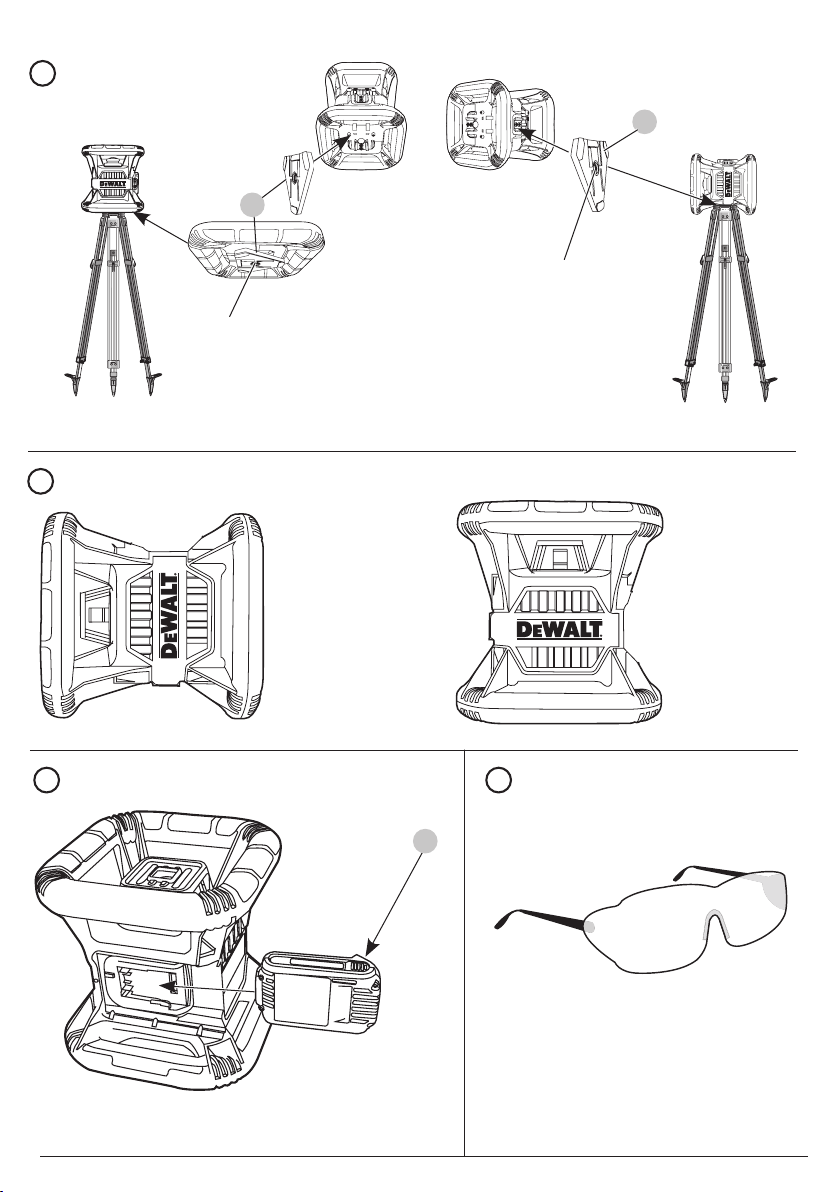
Using the Laser on a Tripod (Fig. C)
1. Position the tripod securely and set it to the desired height.
2. Make sure that the top of the tripod is roughly level. The
laser will self-level only if the top of the tripod is within ± 5˚
of level. If the laser is set up too far out of level, it will beep
when it reaches the limit of its leveling range. No damage
will be done to the laser, but it will not operate in an “out of
level” condition.
3. Secure the laser to the tripod by attaching the tripod
20
adapter
adapter may be assembled to the bottom for level mode
or to the side for plumb mode. Place the assembly on the
tripod and screw the threaded knob on the tripod into the
female thread on the tripod adapter.
as shown in Figure C to the laser body. The
NOTE: Be sure that the tripod you are working with has a
5/8"–11 threaded screw to ensure secure mounting.
4. Turn the laser on and adjust the rotation speed and controls
as desired.
Using the Laser on a Floor (Fig. D)
The laser level can be positioned directly on the floor for
leveling and plumbing applications such as framing walls.
1. Place the laser on a relatively smooth and level surface
where it will not be disturbed.
2. Position the laser for a level or plumb setting as shown.
3. Turn the laser on and adjust the rotation speed and controls
as desired.
NOTE: The laser will be easier to set up for wall applications if
the rotation speed is set to 0 rpm's and if the remote control is
used to line up the laser with control marks. The remote allows
one person to set up the laser.
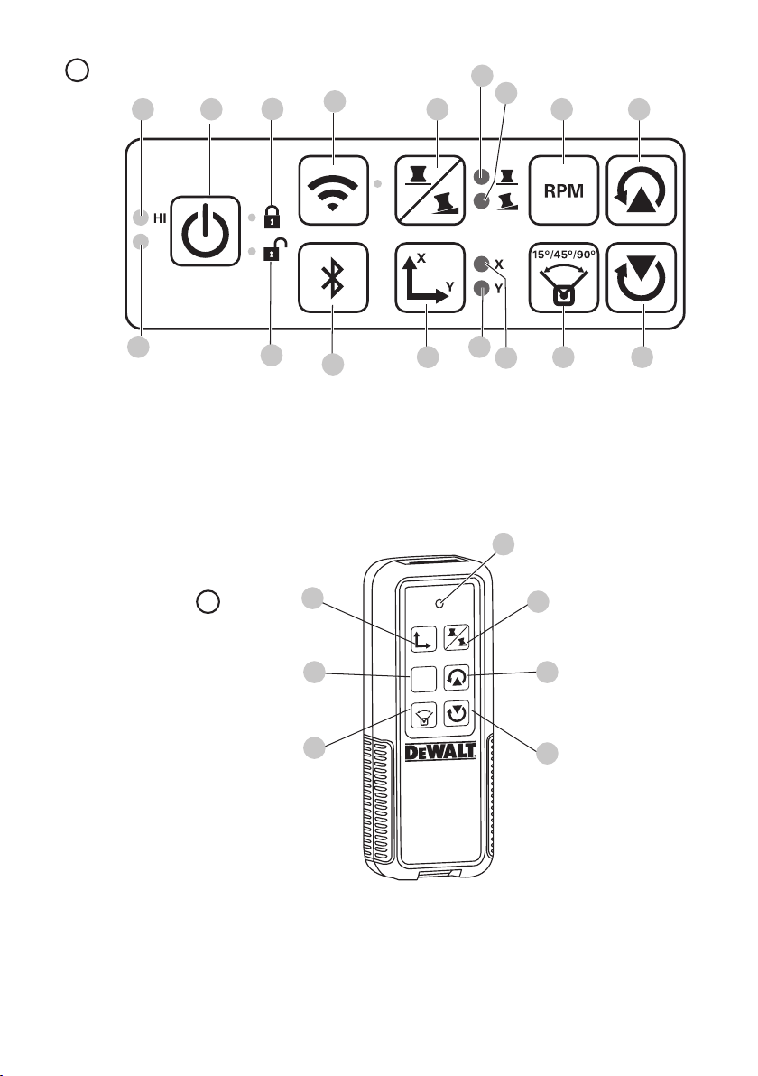
Using the DW080LRS/LGS Remote
The remote control allows one person to operate and set up
the laser from a distance. The remote is powered by a Li-Ion
battery. Use the USB port to charge the battery.
You must press the radio waves button
order to use the remote.The LED light on the remote control
(Figure B
DW080LRS/LGS laser unit.
NOTE: Whenever Bluetooth® is enabled on the laser, you will
NOT be able to use the remote.
Any remote could control the laser unless the laser is paired to
one remote.
• If the laser is not paired to the remote, the unlocked
• If the laser is paired to the remote, the locked
You can use all the buttons on the keypad to control the
laser unit. To completely power OFF a DW080
laser unit using the Remote keypad, press the X-Y
button
14
1
) indicates a signal is being transmitted from the
LED will be lit on the laser keypad to indicate that any
remote can control the laser.
be lit to indicate that currently only one remote can control
the laser.
14
(
)
and the MODE button
on the laser in
13
(
)
simultaneously.
LED will
LRS/LGS
axis
ENGLISH

ENGLISH
Specifications
SKU
Laser Wavelength 630-680nm 515-530nm
Laser Power/Class ≤ 5mw /CLASS 3R ≤ 5mw /CLASS 3R
Rotation Speed 150, 300, 600, 1200 RPM 150, 300, 600, 1200 RPM
Self-Leveling Range ± 5° ± 5°
Indoor Visibile Range 200' (60 m) diameter 250' (80 m) diameter
Range with Detector 2000' (600 m) diameter 2000' (600 m) diameter
Leveling Accuracy +/- 1/16” per 100’
Power Source 20V D
Operating Temperature 23°F to 122°F
Storage Temperature -4°F to 158°F
Environmental Water resistant Water resistant
DW080LRS DW080LGS
630-680nm
(+/- 1.5 mm per 30m)
eWALT batteries 20V DeWALT batteries
(-5°C to 50°C)
(-20°C to 70°C)
+/- 1/16” per 100’
(+/- 1.5 mm per 30m)
23°F to 122°F
(-5°C to 50°C)
-4°F to 158°F
(-20°C to 70°C)
Accessories
Recommended accessories for use with your tool are available
for purchase at your factory-owned local service center.
WARNING: Since accessories, other than those
offered by DeWALT, have not been tested with this
product, use of such accessories with this tool could be
hazardous. To reduce the risk of injury, only
recommended accessories should be used with this
product.
If you need assistance in locating any accessory, please
contact
DeWALT Industrial Tool Co., 701 East Joppa Road,
Towson, MD 21286, call 1–800–4-DeWALT (1–800–433–9258)
or visit our website www.DeWALT.com
Digital Laser Detector (Fig. H–K)
Some laser kits include a DeWALT Digital Laser Detector. The
DeWALT Digital Laser Detector allows you to locate a laser
beam emitted by a rotary laser in bright light conditions or over
long distances. The detector can be used in both indoor and
outdoor situations where it is difficult to see the laser beam.
The detector is not for use with non-rotating lasers but is
compatible with most rotary red-beam (DW0743R) and green
beam (DW0743G) lasers. It can be set to indicate the location
of the beam to either the nearest 1/8" (3 mm) or the nearest
1/25" (1 mm). The detector gives both visual signals through
the display window
23
to indicate the location of the laser beam.
The
DeWALT Digital Laser Detector can be used with or without
the detector clamp. When used with the clamp, the detector can
be positioned on a grade rod, leveling pole, stud or post.
Installing a Battery in the Detector (Fig. H)
The Digital Laser Detector is powered by a 9 volt battery. To
install the battery provided, lift up on the battery compartment
21
cover
the battery as shown.
22
and audio signals through the speaker
. Place the 9 volt battery in the compartment, aligning
DeWALT,
Detector Controls (Fig. I)
The detector is controlled by the power button
accuracy mode button
27
.
When the power button is pushed once, the detector is turned
on. The top of the display window shows the accuracy icon
27
, and the volume icon
28
. To decrease the volume of the
audible signal that the detector emits when it senses a laser
beam, push the button again; one of the half circles next to the
horn icon will dissappear. To turn off the audible signal push the
button a third time; the volume icon will dissapear. The
Digital Laser Detector also has an auto shut-off feature. If a
rotary laser beam does not strike the beam detection window,
or if no buttons are pressed, the detector will shut itself off in
about 30 minutes.
When the detector is on, the top of the window shows an
accuracy mode icon. Either the ±1/25" (1 mm) accuracy mode
53
icon
will appear, or the ±1/8" (3 mm) accuracy mode icon
54
will appear. When the ±1/25" (1 mm) accuracy mode icon
appears, it indicates that the detector will give an “on grade”
reading only when the laser beam is on grade or no more
than 1/25" (1 mm) above or below it. When the 1/8" (3 mm)
accuracy mode icon appears, it indicates that the detector will
give an “on grade” reading when the laser beam is on grade
or approximately 1/8" (3 mm) above or below it. Push the
27
accuracy mode button
once to change the accuracy mode.
26
and the
DeWALT
Detector Operation (Fig. I, J)
1. Set up and position the rotary laser that you will be using
according to the manufacturer’s directions. Turn the laser
on and make sure that the laser is rotating and emitting a
laser beam. NOTE: This detector has been designed to be
used only with a rotating laser. The detector will not work
with a stationary beam laser level.
2. Turn the detector on by pressing the power/volume
26
button
.
3. Adjust the volume as desired as described in the
Detector Controls.
4. Position the detector so that the detector window
facing the laser beam produced by the rotary laser. Move
the detector up or down within the approximate area of the
beam, until you have centered the detector. For information
about the display window indicators and the audible signal
indicators, refer to the table titled Indicators (Fig.
5. Use the marking notches
30
to accurately mark the
position of the laser beam.
Detector Cleaning and Storage
• Dirt and grease may be removed from the exterior of the
detector using a cloth or soft, non-metallic brush.
• The D
eWALT Digital Laser Detector is waterproof. If you
should drop the detector in mud, wet concrete, or a similar
substance, simply hose the detector off. Do not use high
pressure water, e.g., from a pressure washer.
• The best storage place is one that is cool and dry–away
from direct sunlight and excess heat or cold.
22
J
is
).
15

Detector Service
Except for batteries, there are no user serviceable parts in the
Digital Laser Detector. Do not disassemble the unit. Unauthorized tampering with the laser detector will void all warranties.
Detector Troubleshooting
The detector will not turn on.
• Press and release the power/volume button.
• Check to see that the battery is in place and in the
proper position.
• If the detector is very cold, allow it to warm up in a
heated area.
• Replace the 9 volt battery. Turn the unit on.
• If the detector still does not turn on, take the detector to a
DeWALT service center.
The detector’s speaker makes no sound.
• Ensure that the detector is on.
• Press the power/volume button. It will toggle from high, to
low, to mute.
• Ensure that the rotary laser is spinning and that it is emitting
a laser beam.
• If the detector is still not making any sound, take it to a
DeWALT service center.
The detector does not respond to a stationary laser beam.
The
DeWALT Digital Laser Detector has been designed to work
only with rotary lasers.
The detector gives off a tone but the LCD display window
does not function.
• If the detector is very cold, allow it to warm up in a
heated area.
• If the LCD display window is still not functioning, take the
detector to a
DeWALT service center.
Mounting Bracket (Fig. C, M)
Some laser kits include a Wall Mount. It can be used for
attaching the tool to track or ceiling angle and to aid in
acoustical ceiling installation. Follow the directions below for
using the wall mount.
CAUTION: Before attaching the laser level to wall
track or ceiling angle, be sure that the track or angle is
properly secured.
1. Place the laser on the mounting base
11 screw hole on the tripod adapter (
to the bottom of the laser with the hole
base. Turn the mounting knob
2. With the wall mount measuring scale
the wall mount clamp locking knob
jaws.
3. Position the clamp jaws around the wall track or ceiling
angle and tighten the wall mount clamp locking knob
42
to close the clamp jaws onto the track. Be sure that
the wall mount clamp locking knob is securely tightened
before proceeding.
37
aligning the 5/8–
20
, Fig. C) attached
39
40
in the mounting
to secure the laser.
41
facing you, loosen
42
to open the clamp
CAUTION: Always use a ceiling wire hanger or
equivalent material, in addition to the wall mount
clamp locking knob, to help secure the laser level
while mounting it to a wall. Thread the wire through
the handle of the laser level. DO NOT thread the wire
through the protective metal cage. Additionally, screws
may be used to fasten the wall mount directly to the
wall as a back up. Screw holes
top of the wall mount.
4. Using the base leveling knob
position from the wall.
5. The tool can be adjusted up and down to the desired offset
height for working. To change the height, loosen the locking
45
knob
located on the left of the wall mount. Support the
mounting base when adjusting the height.
6. Turn the adjustment knob
wall mount, to move the laser level up and down to set your
height. Use the wall mount measuring scale
your mark.
NOTE: It may be helpful to turn the power on and turn the
rotary head so that it puts a dot on one of the laser scales.
DeWALT target card is marked at 1–1/2" (38 mm),
The
therefore, it may be easiest to set the offset of the laser to
1–1/2" (38 mm) below the track.
7. Once you have positioned the laser at the desired height,
tighten the locking knob
45
43
are located at the
44
approximate a level
46
, located to the right of the
41
to maintain this position.
to pinpoint
Mounting on a Grade Rod (Fig.K)
To secure your detector to a grade rod, first attach the detector
to the clamp using the 1/4"-20 threaded knob
of the clamp. Slide the tracks
33
on the grade rod.
1. Position the detector at the height needed and turn the
clamp knob clockwise to tighten the jaws of the clamp
around the grade securing the clamp on the rod.
2. To make adjustments in height, slightly loosen the clamp,
reposition and retighten.
32
on the clamp around the rail
47
on the back
Construction Grade Rod (Fig. L)
DANGER: NEVER attempt to use a grade rod in a
storm or near overhanging electric wires. Death or
serious personal injury will occur.
Some laser kits include a grade rod. The
Rod is marked with measurement scales on both sides and
is constructed in telescoping sections. A spring-loaded button
actuates a lock to hold the grade rod at various lengths.
The front of the grade rod has the measurement scale starting
at the bottom. Use this for measuring from the ground up when
grading or leveling jobs.
The back of the grade rod is designed to measure the height
of ceilings, joists, etc. Fully extend the top section of the grade
rod until the button locks into the previous section. Extend that
section either until it locks into the adjacent section or until the
grade rod touches the ceiling or joist. The height is read where
the last extended section exits the previous lower section, as
shown in Figure
16
L
.
DeWALT Grade
ENGLISH

ENGLISH
Target Card (Fig. G)
Some laser kits include a Laser Target Card to aid in locating
and marking the laser beam. The target card enhances the
visibility of the laser beam as the beam crosses over the card.
The card is marked with standard and metric scales. The laser
beam passes through the red plastic and reflects off of the
reflective tape on the reverse side. The magnet at the top of
the card is designed to hold the target card to ceiling track or
steel studs to determine plumb and level positions. For best
performance when using the Target Card, the
should be facing you.
DeWALT logo
Laser Enhancement Glasses (Fig. F)
Some laser kits include a pair of Laser En hancement Glasses.
These glasses improve the visibility of the laser beam under
bright light conditions or over long distances when the laser is
used for interior applications. These glasses are not required to
operate the laser.
CAUTION: These glasses are not ANSI approved
safety glasses and should not be worn while operating
other tools. These glasses do not keep the laser beam
from entering your eyes.
DANGER: To reduce the risk of serious personal injury,
never stare directly into the laser beam, with or without
these glasses.
Maintenance
• Under some conditions, the glass lens may collect some
dirt or debris. This will affect beam quality and operating
range. The lens should be cleaned with a cotton swab
moistened with water.
• The flexible rubber shield can be cleaned with a wet lintfree cloth such as a cotton cloth. USE WATER ONLY — DO
NOT use cleansers or solvents. Allow the unit to air dry
before storing.
• To maintain the accuracy of your work, check the calibration
of the laser often. Refer to Calibrating the Laser.
• Calibration checks and other maintenance repairs can be
performed by
checks are included under the DeWALT One Year Free
Service Con tract.
• When the laser is not in use, store it in the kit box provided.
• Do not store your laser in the kit box if the laser is wet. Dry
exterior parts with a soft, dry cloth and allow the laser to
air dry.
• Do not store your laser at temperatures below 0˚F (-18˚C)
or above 105˚F (41˚C).
DeWALT service centers. Two free calibration
WARNING: Never use solvents or other harsh
chemicals for cleaning the non-metallic parts of the
tool. These chemicals may weaken the materials used
in these parts. Use a cloth dampened only with water
and mild soap. Never let any liquid get inside the unit;
never immerse any part of the unit into a liquid. Never
use compressed air to clean the laser.
Troubleshooting
Height of Instrument Alert
The DW080LRS/DW08LGS has a built-in alarm feature that
alerts the operator if the unit is disturbed after the unit has selfleveled. The laser unit will stop rotating, the control panel LED
indicator light will flash, and the beeper will sound.
Turning the Laser Off
Press the the power button for 3 sec to turn the laser off. The
power LED indicator light will no longer be illuminated.
To Reset The Laser Unit for Continued Use
Turn the unit off and back on again using the power button on
the laser unit control panel.
NOTE: Always recheck the laser setup after the Height of
Instrument Alert (Hi mode) has triggered.
Service and Repairs
NOTE: Disassembling the laser level will void all warranties on
the product.
To assure product SAFETY and RELIABILITY, repairs,
maintenance and adjustment should be performed by
authorized service centers. Service or maintenance performed
by unqualified personnel may result in a risk of injury. To locate
your nearest D
(1–800–433–9258) or visit our website: www.DeWALT.com.
Register Online
Thank you for your purchase. Register your product now for:
• WARRANTY SERVICE: Registering your product will help
you obtain more efficient warranty service in case there is a
problem with your product.
• CONFIRMATION OF OWNERSHIP: In case of an
insurance loss, such as fire, flood or theft, your registration
of ownership will serve as your proof of purchase.
• FOR YOUR SAFETY: Registering your product will allow
us to contact you in the unlikely event a safety notification is
required under the Federal Consumer Safety Act.
Register online at www.dewalt.com/register.
eWALT service center call 1–800–4-DeWALT
17

Three Year Limited Warranty
DeWALT will repair, without charge, any defects due to faulty
materials or workmanship for three years from the date of
purchase. This warranty does not cover part failure due to
normal wear or tool abuse. For further detail of warranty
coverage and warranty repair information, visit www.
com or call 1–800–4-DeWALT (1–800–433–9258). This
warranty does not apply to accessories or damage caused
where repairs have been made or attempted by others. This
warranty gives you specific legal rights and you may have other
rights which vary in certain states or provinces.
In addition to the warranty,
DeWALT will maintain the tool and replace worn parts caused
by normal use, for free, any time during the first year after
purchase.
90 DAY MONEY BACK GUARANTEE
If you are not completely satisfied with the performance of your
DeWALT Power Tool, Laser, or Nailer for any reason, you can
return it within 90 days from the date of purchase with a receipt
for a full refund – no questions asked.
RECONDITIONED PRODUCT: Reconditioned product is
covered under the 1 Year Free Service Warranty. The 90 Day
Money Back Guarantee and the Three Year Limited Warranty
do not apply to reconditioned product.
FREE WARNING LABEL REPLACEMENT: If your warning
labels become illegible or are missing, call 1–800–4visit your local service center for a free replacement.
DeWALT tools are covered by our:
1 YEAR FREE SERVICE
DeWALT.
DeWALT or
ENGLISH
18

DeWALT BATTERY AND CHARGER SYSTEMS/ SYSTÈMES DE BATTERIES ET DE
CHARGEURS DeWALT /BATERÍA Y SISTEMAS DE CARGADORES DeWALT/BATERIA E
SISTEMAS DE CARREGADOR DeWALT
Chargers/Charge Time (Minutes)
Chargeurs/Temps de chargement (minutes)
Cargadores/tiempo de carga (minutos)
Carregadores/tempo de carga (minutos)
Battery Cat /
Nº de cat.
batterie /N.°
de catálogo
batería/Nº
de Categoria
da Bateria
DCB203BT* 20 X X X X 35 35 35 90 60 45 X 30 30 30 60 X
DCB204BT* 20 X X X X 70 70 70 185 120 90 X 60 60 60 120 X
*BT - Bluetooth
SIG, Inc. and any use of such marks by
respective owners.
**Battery Datecode 201536 or later.
*BT - Bluetooth
utilisées sous licence par DeWALT. Les autres marques de commerce et les appellations commerciales appartiennent à leurs
propriétaires respectifs.
**Code-date de batterie 201536 ou ultérieur.
*BT - Bluetooth
Bluetooth®, SIG, Inc. y todo uso de dichas marcas por DeWALT se hace bajo licencia. Otras marca y nombres comerciales son
de sus respectivos propietarios.
** Código de fecha de la batería 201536 o posterior.
*BT - Bluetooth
Bluetooth® SIG Inc. e quaisquer usos dessas marcas pela DeWALT são feitos sob licença. Outras marcas registradas ou
comerciais pertencem aos respectivos proprietários.
**Bateria com código de data 201536 ou posterior.
“X” Indicates that the battery pack is not compatible with that specific charger. All charge times are approximate. Actual charge time
may vary. Read the instruction manual for more specific information.
Le «X» indique que le bloc batterie n’est pas compatible avec ce chargeur spécifique. Tous les temps de chargement sont
approximatifs. Le temps de chargement réel peut varier. Lisez le mode d’emploi pour plus d’informations spécifiques.
La “X” indica que el paquete de baterías no es compatible con ese cargador específico. Todos los tiempos de carga son aproximados.
El tiempo de carga real puede variar. Lea el manual de instrucciones para obtener información más específica.
“X” Indica que o pack de baterias não está compatível ao carregador específico. Todos os tempos de carregamento são estimativas. O
tempo de carregamento real pode variar. Leia o Manual de Instruções para mais informações específicas.
*** Maximum initial battery voltage (measured without a workload) is 20 volts. Nominal voltage is 18.
*** La tension initiale maximale de la batterie (mesurée sans charge) est de 20 volts. La tension nominale est de 18volts.
*** La tensión inicial máxima de la batería (medida sin una carga de trabajo) es de 20 voltios. La tensión nominal es de 18.
*** A tensão inicial máxima da bateria (medida sem carga) é de 20 volts. A tensão nominal é 18.
Output
120 Volts 12 Volts
Voltage/
Tension
de sortie
de la
/Tensión
de salida/
DC9000
DC9310
DC9320
DCB095
DCB101
DCB102
DCB103
DCB107
DCB112
DCB113
DCB114
DCB115
DCB118
DCB132
DCB119
Tensão de
saída
DCB606 60/20 X X X X 100 100 100 272 170 140 X 90 60 90 X X
DCB200 20 X X X X 60 60 60 140 90 67 X 45 45/30** 45 90 X
DCB201 20 X X X X 30 30 30 70 45 35 X 22 22 22 45 X
DCB203 20 X X X X 35 35 35 90 60 45 X 30 30 30 60 X
DCB204 20 X X X X 70 70 70 185 120 90 X 60 60/40** 60 120 X
DCB205 20 X X X X 95 95 95 240 150 112 X 75 75/47** 75 150 X
DCB207 20 X X X X 30 30 30 60 40 30 X 22 22 22 X X
®
NOTE: The Bluetooth® word mark and logos are registered trademarks owned by the Bluetooth®,
DeWALT is under license. Other trademarks and trade names are those of their
MD
REMARQUE: Bluetooth
®
NOTA: La marca denominativa y los logotipos de Bluetooth® son marcas registradas propiedad de
®
OBSERVAÇÃO: A marca nominativa e os logotipos Bluetooth® são marcas registradas da
MD
et ses logos sont des marques déposées de BluetoothMD SIG, Inc. et sont
DW0249

Solamente para propósito de Argentina:
Importado por: Black & Decker Argentina S.A.
Pacheco Trade Center
Colectora Este de Ruta Panamericana
Km. 32.0 El Talar de Pacheco
Partido de Tigre
Buenos Aires (B1618FBQ)
República de Argentina
No. de Importador: 1146/66
Tel. (011) 4726-4400
Solamente para propósito de México:
Importado por: Black & Decker S.A. de C.V.
Avenida Antonio Dovali Jaime, # 70 Torre B Piso 9
Colonia Santa Fé
Delegación Alvaro Obregón
México D. F.: 01210
Tel. (52) 555-326-7100
R.F.C.: BDE810626-1W7
Solamente para propósito de Colombia:
Importado por: Black & Decker de Colombia S.A.S
Cra 85D #46A-65 Bodega 23
Complejo Logístico San Cayetano
Tel. (57) 1-744 – 71 - 00
Bogotá
Colombia
Imported by/Importado por:
Black & Decker do Brasil Ltda.
Rod. BR 050, s/n° - Km 167
Dist. Industrial II
Uberaba – MG – Cep: 38064-750
CNPJ: 53.296.273/0001-91
Insc. Est.: 701.948.711.00-98
S.A.C.: 0800-703-4644
Made in China
Hecho en China
Fabricado no China
DeWALT Industrial Tool Co., 701 East Joppa Road, Towson, MD 21286
(MARCH 2018) Part No. Nxxxxxx
The following are trademarks for one or more DeWALT power tools: the yellow and black color scheme, the “D” shaped air intake grill,
the array of pyramids on the handgrip, the kit box configuration, and the array of lozenge-shaped humps on the surface of the tool.
DW080LRS, DW080LGS Copyright © 2018 DeWALT
 Loading...