

E
NL
GR
PT
FIN
HU
BG
LV
ES
DK
CZ
E
NO
SK
RO
LT
F
SE
RU
PT
PL
SI
EE
TR
HR
DW0330S
User Manual
DW0330S
www.DEWALT.com
Please read these instructions before operating the product.
Figures
A
1
B
1
2
2
3
DW0330S
6
4
5
DW0330S
DW0330S
FCC ID: xxxxxDW0165S
FCC ID: 2ANWFDW0330
IC: xxxxx-DW0165S
IC: 23237-DW0330
4.5V DC
4.5V DC
7
8
2
C
3
1
4
5
6
D
AAA
AAA
AAA
AA
A
AAA
2
E
1
=
F
2
3
4
=
=
=
G
H
≤ 45°
I
≤ 45°
3
Contents
E
• User Safety
• Battery Safety
• Loading Batteries
• Using the Tool
• Warranty
• Error Codes
•
Retain all sections of this manual for future reference.
User Safety
WARNING:
Carefully read the Safety Instructions and
Product Manual before using this product. The
person responsible for the product must ensure
that all users understand and adhere to these
instructions.
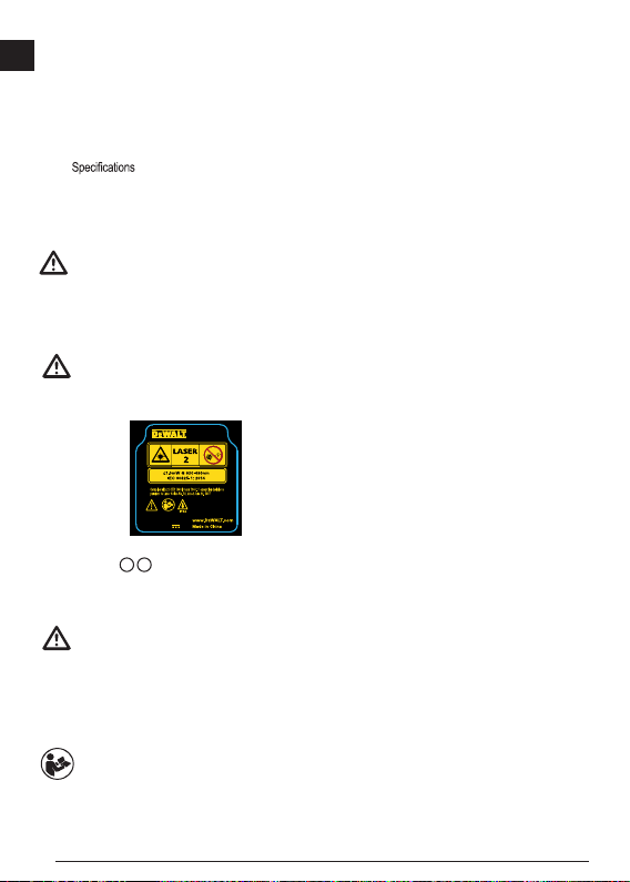
WARNING:
The following label information is placed on your
laser tool to inform you of the laser class for your
convenience and safety.
DW0330S
DW0330S
FCC ID: xxxxxDW0165S
IC: xxxxx-DW0165S
FCC ID: 2ANWFDW0330
IC: 23237-DW0330
4.5V DC
4.5V DC
The DW0330S tool emits a visible laser beam, as
shown in Figure A 1 . The laser beam emitted is
Laser Class 2 per IEC 60825-1 and complies with 21
CFR 1040.10 and 1040.11 except for deviations
pursuant to Laser Notice No. 50, dated June 24, 2007.
WARNING:
While the laser tool is in operation, be careful not
to expose your eyes to the emitting laser beam
(red light source). Exposure to a laser beam
for an extended time period may be hazardous
to your eyes. Do not look into the beam with
optical aids.
WARNING: To reduce the risk of injury, user
must read the Product User manual, Laser
Safety manual, and Battery Safety information.
4
Battery Safety
WARNING: Batteries can explode or leak and
cause serious injury or re. To reduce the risk:
ALWAYS follow all instructions and warnings on
the battery label and package.
DO NOT short any battery terminals.
DO NOT charge alkaline batteries.
DO NOT mix old and new batteries. Replace all
of them at the same time with new batteries of
the same brand and type.
DO NOT mix battery chemistries.
DO NOT dispose of batteries in re.
ALWAYS keep batteries out of reach of children.
ALWAYS remove batteries if the device will not
be used for several months.
NOTE: Ensure that the recommended batteries
are used.
NOTE: Ensure the batteries are inserted in the
correct manner, with the correct polarity.
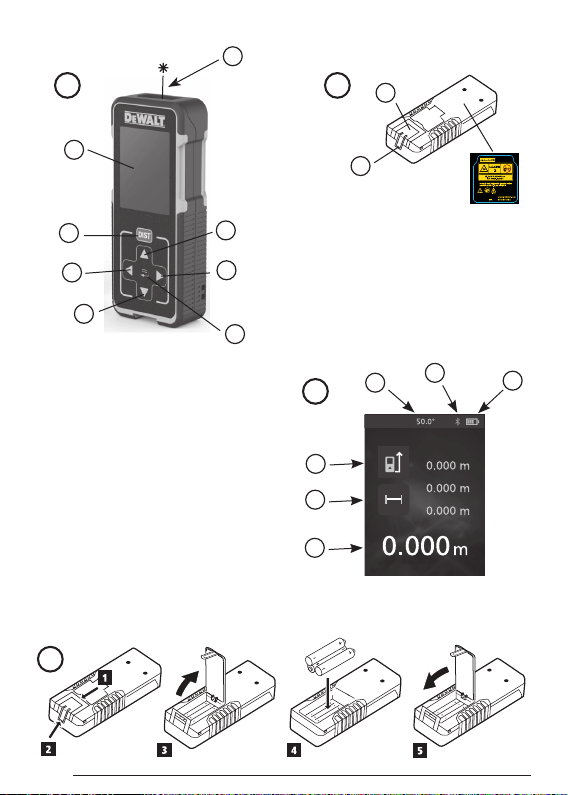
Loading Batteries
1.
Pull up the tool stand on the back of the tool (Figure
D 1
).
2.
Pull up the battery compartment latch on the back of
the tool (Figure D 2 and D 3).
3.
Insert three AAA batteries, making sure to position
the - and + ends of each battery as noted inside the
battery compartment (Figure
4.
Push the battery door down until it snaps in place
(Figure D 5).
When the tool is ON, the battery level appears in the
display window (Figure
C 1
D 4
).
).
Using the Tool
Measuring Distance to a Wall or Object
1.
Point the tool's laser (Figure A 1) toward a wall or
object, and not toward anyone's eyes.
2.
Click (Figure A 3) to turn the tool on.
3.
By default, distances are measured from the bottom
of the tool to a wall or object (Figure
To measure distances from the top or middle of the
tool, or from the tool's endpiece (when it is flipped
open to measure from a corner), click
4.
Point the tool's laser (Figure A 1) toward the wall
or object whose distance you need to measure.
5.
Click to measure the distance from the tool to
the wall or object.
6.
At the bottom of the display window, view the current
measurement (Figure
To take a new measurement, click
current measurement up to the previous line on the
display window. Then repeat steps 4-6.
C 6
).
E 3
).
.
to move the
Measuring Distances Continuously
To take a series of measurements as you move around,
change to Continuous Measure mode.
1.
Point the tool's laser (Figure A 1) toward a wall or
object, and not toward anyone's eyes.
2.
Click (Figure A 3) to turn the tool on.
3.
By default, distances are measured from the bottom
of the tool to a wall or object (Figure E 3).
To measure distances from the top or middle of the
tool, or from the tool's endpiece (when it is flipped
open to measure from a corner), click
4.
Press to turn on the Continuous Measure mode
(Figure C 5).
5.
Point the tool's laser (Figure A 1) toward the wall
or object whose distance you need to measure.
6.
At the bottom of the display window, view the current
measurement (Figure C 6), which will keep
changing as you move the tool.
7.
To take the current measurement (from the tool to the
wall or object) and exit Continuous Measure mode,
.
click
To take a new measurement, click
current measurement up to the previous line on the
display window. Then repeat steps 4-7.
.
to move the
E
5

Measuring Area
E
You can measure the area of a wall, floor, or object.
1.
Point the tool's laser (Figure A 1) toward a wall or
object, and not toward anyone's eyes.
2.
Click (Figure A 3) to turn the tool on.
3.
By default, distances are measured from the bottom
of the tool to a wall or object (Figure
To measure distances from the top or middle of the
tool, or from the tool's endpiece (when it is flipped
open to measure from a corner), click
4.
Click .
5.
Click .
6.
Click to determine the area of one wall, floor, or
object, or click
two walls, floors, or objects.
7.
Measure the width.
• Point the top of the tool at one side of the target
(wall, floor, or object).
• Position the tool at one end of the target and
point the laser dot across the width. (Figure
1
shows where to position the tool if you are
measuring from the bottom of the tool.)
• Click
the top of the display window.
8.
Measure the length.
• Position the tool at one end of the target and
point the laser dot across the length. (Figure
2
shows where to position the tool if you are
measuring from the bottom of the tool.)
• Click
the second line of the display window.
9.
View the Area measurement at the bottom of the
display window (Figure C 6).
to add or subtract the areas of
to display the width measurement at
to display the length measurement on
6
E 3
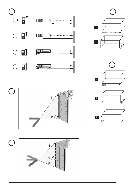
Measuring Volume
You can measure the volume of a room or object.
1.
Click (Figure A 3) to turn on the tool.
2.
By default, distances are measured from the bottom
of the tool to a wall or object (Figure E 3).
To measure distances from the top or middle of the
).
.
F
tool, or from the tool's endpiece (when it is flipped
open to measure from a corner), click
3.
Click twice to show on the display window
(Figure C 5).
4.
Measure the width.
• Point the top of the tool at one side of the target
(room or object).
• Position the tool at one end of the target and
point the laser dot across the width. (Figure
1
shows where to position the tool if you are
measuring from the bottom of the tool.)
• Click
5.
Measure the length.
• Position the tool at one end of the target and
• Click
6.
Measure the height.
F
• Positon the tool at one end of the target and
• Click
10.
View the Volume measurement at the bottom of the
display window (Figure C 6).
to display the width measurement at
the top of the display window.
point the laser dot across the length. (Figure
2
shows where to position the tool if you are
measuring from the bottom of the tool.)
to display the length measurement on
the second line of the display window.
point the laser dot across the height. (Figure
3
shows where to position the tool if you are
measuring from the bottom of the tool).
to display the height measurement on
the third line of the display window.
.
G
G
G
Measuring the Height of a Tall Object
If you nee d to measure the hei ght of a tall objec t (e.g.,
a tall bui lding), you can cal culate the heig ht based on
the dist ances from the same point to 2 or 3 poi nts on
the obje ct. The tool wil l use the Pythagorean Theorem
(C2=A2+B2) to calculate the height.
• If the too l can be positi oned opposite t he bottom
of the tal l object (to creat e an angle ≤ 45°), use
the dist ances to 2 points to calcul ate the height
(Figure H).
• If the too l must be pointed d ownward to aim at
the bot tom of the tall obj ect (to create an angle >
45°), use the dis tances to 3 points to calc ulate the
height (Figure
I
).
Using t he Distance s to 2 Points
1.
Click (Figure A 3) to turn on th e tool.
2.
Click 3 times to s how on the dis play
window (Figure C #4).
3.
Aim the lase r at the top of the tool ( Figure A 1)
at the highest point o f the building or object who se
height yo u need to measure (F igure
4.
Click to measure th e distance to the t op of
the tall object.
5.
From the same point, aim the lase r at the lowest
point of the buildin g or object (Figure H 2).
6.
Click to measure th e distance.
7.
On the bottom line of the d isplay window, vie w the
height of the building or object.
H 1
).
Using t he Distance s to 3 Points
1.
Click (Figure A 3) to turn on th e tool.
2.
Click 4 times to s how on the dis play window
(Figure C #4).
3.
Point the las er (Figure A 1) at the highest point
of the building or object whos e height you need to
measure (Figure
4.
Click to measure th e distance to the t op of
the tall object.
5.
From the same point, aim the lase r on a horizontal
line str aight ahead towar d the building or ob ject
(Figure
6.
Click to measure th e distance.
7.
From the same point, aim the lase r at the lowest
point of the buildin g or object (Figure I 3).
8.
Click to measure th e distance.
I 2
I 1
).
).
9.
On the bottom line of the d isplay window, vie w the
height of the building or object.
Adding Measurements
You can add two measurements to get a total
measurement of the two distances.
1.
Click (Figure A 3) to turn on the tool.
2.
By default, distances are measured from the bottom
of the tool to a wall or object (Figure E 3).
To measure distances from the top or middle of the
tool, or from the tool's endpiece (when it is flipped
open to measure from a corner), click
3.
Point the tool's laser (Figure A 1) toward the wall
or object whose distance you need to measure.
4.
Click to measure the distance from the tool to
the wall or object.
5.
Indicate that you want to add this measurement to the
next measurement. ---- may not need this step
6.
Point the tool's laser toward the next wall or object.
7.
Click to measure the distance and add it to the
previous measurement.
8.
View the total of the two measurements at the bottom
of the display window (Figure C 6).
.
Subtracting Measurements
You can subtract one measurement from another.
1.
Click (Figure A 3) to turn on the tool.
2.
By default, distances are measured from the bottom
of the tool to a wall or object (Figure E 3).
To measure distances from the top or middle of the
tool, or from the tool's endpiece (when it is flipped
open to measure from a corner), click
3.
Point the tool's laser (Figure A 1) toward the wall
or object whose distance you need to measure.
4.
Click to measure the distance from the tool to
the wall or object.
5.
Click twice to indicate that you want to subtract
the next measurement from this measurement.
6.
Point the tool's laser toward the next wall or object.
.
E
7

7.
Click to measure the distance and subtract it
E
from the previous measurement.
8.
View the difference between the two measurements
at the bottom of the display window (Figure C 6).
Changing the Unit of Measure
Once the current measurement is taken (the device is
not in Continuous Measure mode), you can set the unit
of measure to fractional ft (6'02"
decimal ft (6.21 ft), decimal inches (3.21 in), or meters
(1.894 m).
1.
Click .
2.
Click ft/m.
3.
Click the desired unit of measure.
• 0'00" 0/00
• 0" 0/00
• 0'00" ft
• 0.00 in
• 0.000 m
4.
Click to return to the previous screen.
9/16), inches (74 9/16 in),
6.
Use the DW0330S to measure each wall in the room
or space captured in the floor plan, and sync the
measurements to the floor plan.
7.
Using the DEWALT® Tool Connect application, save
the floor plan.
Once you have saved the floor plan, you can export it to
one of several different file formats, including PDF, DXF,
or JPG, and print it or email it to other people (your realtor,
home center, etc.).
“THE BLUETOOTH® WORD MARK AND LOGOS ARE REGISTERED TRADEMARKS OWNED BY BLUETOOTH SIG, INC. AND
ANY USE OF SUCH MARKS BY DEWALT INDUSTRIAL TOOL CO.
IS UNDER LICENSE. OTHER TRADEMARKS AND TRADE NAMES
ARE THOSE OF THEIR RESPECTIVE OWNERS.”
Turning Off the Sound
Each time you take a measurement, the tool will beep.
You can turn off the beeps.
1.
On the touchscreen, click .
2.
Click to display .
3.
Click to return to the previous screen.
Using Your DW0330S With
You can use the Bluetooth® capability of your DW0330S
to pair it with the DEWALT® Tool Connect application
on your cell phone or tablet, and then record accurate
measurements in your floor plans.
1.
From either or , download
the DEWALT® Tool Connect application to your cell
phone or tablet.
2.
Using the DEWALT® Tool Connect application,
capture the room or space for which you want to
record the measurements, and build your floor plan.
3.
On the DW0330S keypad, click to turn on the
tool.
4.
If the Bluetooth® icon does not appear on the display
window (Figure
• Click
• Click
5.
Use the DEWALT® Tool Connect application to pair
your cell phone or tablet to the DW0330S.
C 2
), turn on Bluetooth®.
- get to Bluetooth option.
- select Bluetooth option.
8
Turning Off the Tool
The tool can be turned off in either of these ways:
• Press and hold
after 10 seconds, the tool will turn off.
• If you do not use the tool for 90 seconds, it will
automatically turn off.
for 10 seconds. When you release

Three Year Limited Warranty
DEWALT will repair, without charge, any defects due to faulty materials or workmanship for three years from the date
of purchase. This warranty does not cover part failure due to normal wear or tool abuse. For further detail of warranty
coverage and warranty repair information, visit www.D
warranty does not apply to accessories or damage caused where repairs have been made or attempted by others. This
warranty gives you specific legal rights and you may have other rights which vary in certain states or provinces.
In addition to the warranty, D
®
EWALT
tools are covered by our:
EWALT.com or call 1–800–4-DEWALT (1–800–433–9258). This
1 YEAR FREE SERVICE
DEWALT will maintain the tool and replace worn parts caused by normal use, for free, any time during the first year after
purchase.
90 DAY MONEY BACK GUARANTEE
If you are not completely satisfied with the performance of your DEWALT Power Tool, Laser, or Nailer for any reason, you
can return it within 90 days from the date of purchase with a receipt for a full refund - no questions asked.
RECONDITIONED PRODUCT: Reconditioned product is covered under the 1 Year Free Service Warranty. The 90 Day
Money Back Guarantee and the Three Year Limited Warranty do not apply to reconditioned product.
FREE WARNING LABEL REPLACEMENT: If your warning labels become illegible or are missing, call 1-800-4-D
or visit your local service center for a free replacement.
EWALT
Error Codes
If INFO appears on the display window with a Code number, perform the corresponding Corrective Action.
Code Description Corrective Action
101 Received Signal Too Weak,
Measuring Time Too Long
102 Received Signal Too High Target is too reective. Use the target plate or change the
201 Too Much Background Light Reduce the background light on the target area.
202 Laser Beam Interrupted Remove the obstacle and repeat the measurement.
203 Insufcient Power Replace the batteries.
301 Temperature Too High Allow the device to cool down to a temperature within the
302 Temperature Too Low Allow the device to warm up to a temperature within the
401 Hardware Error Switch the device on/off several times. If the error still occurs,
402 Unknown Error Contact the Service Center or distributor. Refer to the Warranty.
Use the target plate or change the target surface.
target surface.
specied Operating Temperature Range.
specied Operating Temperature Range.
return the defective device to the Service Center or distributor.
Refer to the Warranty.
E
9

Specications
E
Range 6in to 330ft (.15m to 100m)
Measuring Accuracy* ± 1/16in (± 1.5mm)*
Resolution** 1/16in (1mm)**
Laser Class
Laser Type ≤ 1.0mW @ 620-690nm
Laser/Backlight Automatic Switch-off After 30s
Unit Automatic Switch-off After 90s
Continuous Measuring Yes
Area Yes
Volume Yes
Pythagoras 2-Point Yes
Pythagoras 3-Point Yes
Endpiece to measure from corners or
grooves
Battery Life (3 x AAA) Up to 3000 Measurements (2500 with
Dimension (H x D x W) 4.72 x 1.91 x 1.02in (120 x 48.5 x 26mm)
Weight (with Batteries) 9.88oz (280g)
Storage Temperature Range 13° F ~ 158° F (-25° C ~ +70 C)
Operating Temperature Range 32° F ~ 104° F (0° C ~ +40° C)
*Measuring Accuracy depends on the current conditions:
• Under favorable conditions (good target surface and room temperature), up to 33ft (10m).
• Under unfavorable conditions (bright sunlight, a very weak reecting target surface, or large temperature uctuations), the
error can increase by to ± 0.003 in/ft (± 0.25mm/m) for distances over 33ft (10m).
**Resolution is the nest measurement you can see. In inches, that is 1/16". In mm, that is 1mm.
Class 2 (IEC/EN60825-1:
Yes. Flip open the endpiece at the bottom of the tool when
you need to t the tool into corners or grooves that are not
at 180° angles. If a corner is at 90°, the endpiece can be
used to hold the tool up against something.
2007/2014)
)
10

Caution—use of controls or adjustments or performance
of procedures other than those specified herein may
result in hazardous radiation exposure.
Caution:
This device complies with Part 15 of the FCC Rules /
Industry Canada licence-exempt RSS standard(s).
Operation is subject to the following two conditions: (1)
this device may not cause harmful interference, and (2)
this device must accept any interference received,
including interference that may cause undesired
operation.
Le présent appareil est conforme aux CNR d'Industrie
Canada applicables aux appareils radio exempts de
licence. L'exploitation est autorisée aux deux conditions
suivantes : (1) l'appareil ne doit pas produire de
brouillage,
et (2) l'utilisateur de l'appareil doit accepter
tout brouillage radioélectrique subi, même si le
brouillage est susceptible d'en compromettre le
fonctionnement.
Changes or modifications not expressly approved by the
party responsible for compliance could void the
authority to operate the equipment.
This equipment has been tested and found to comply
with the limits for a Class B digital device, pursuant to
part 15 of the FCC Rules. These limits are designed to
provide reasonable protection against harmful
interference in a residential installation. This equipment
generates uses and can radiate radio frequency energy
and, if not installed and used in accordance with the
instructions, may cause harmful interference to radio
communications. However, there is no guarantee that
interference will not occur in a particular installation. If
this equipment does cause harmful interference to radio
or television reception, which can be determined by
turning the equipment off and on, the user is
encouraged to tr
communications. However, there is no guarantee that
interference will not occur in a particular installation. If
this equipment does cause harmful interference to radio
or television reception, which can be determined by
turning the equipment off and on, the user is
encouraged to try to correct the interference by one or
more of the following measures:
y to correct the interference to radio
user's
—Reorient or relocate the receiving antenna.
—Increase the separation between the equipment and
receiver.
—Connect the equipment into an outlet on a circuit
different from that to which the receiver is connected.
—Consult the dealer or an experienced radio/TV
technician for help.
11

Notes:

© 2017 DEWALT Industrial Tool Co.,
701 East Joppa Road,
Towson, MD 21286
Made in China
021475
December 2017
 Loading...