


If you have questions or comments, contact us.
Pour toute question ou tout commentaire, nous contacter.
Si tiene dudas o comentarios, contáctenos.
1-800-4-DeWALT
Instruction Manual
Guide D’utilisation
Manual de instrucciones
DCL070
Corded/Cordless Bluetooth® LED Large Area light
with Built-in Charger
Lampe DEL grande surface avec/sans fil, BluetoothMD et
chargeur intégré
Luz LED Bluetooth® con cable/inalámbrica para áreas grandes
con cargador incorporado
final page size: 8.5 x 5.5 in

ENGLISH
English (original instructions) 1
Français (traduction de la notice d’instructions originale) 11
Español (traducido de las instrucciones originales) 22
ENGLISH
Definitions: Safety Alert Symbols and Words
This instruction manual uses the following safety alert symbols and words to alert you to hazardous situations and your risk
of personal injury or property damage.
DANGER: Indicates an imminently hazardous situation which, if not avoided, will result in death or seriousinjury.
WARNING: Indicates a potentially hazardous situation which, if not avoided, could result in death or seriousinjury.
CAUTION: Indicates a potentially hazardous situation which, if not avoided, may result in minor or moderateinjury.
(Used without word) Indicates a safety related message.
NOTICE: Indicates a practice not related to personal injury which, if not avoided, may result in propertydamage.
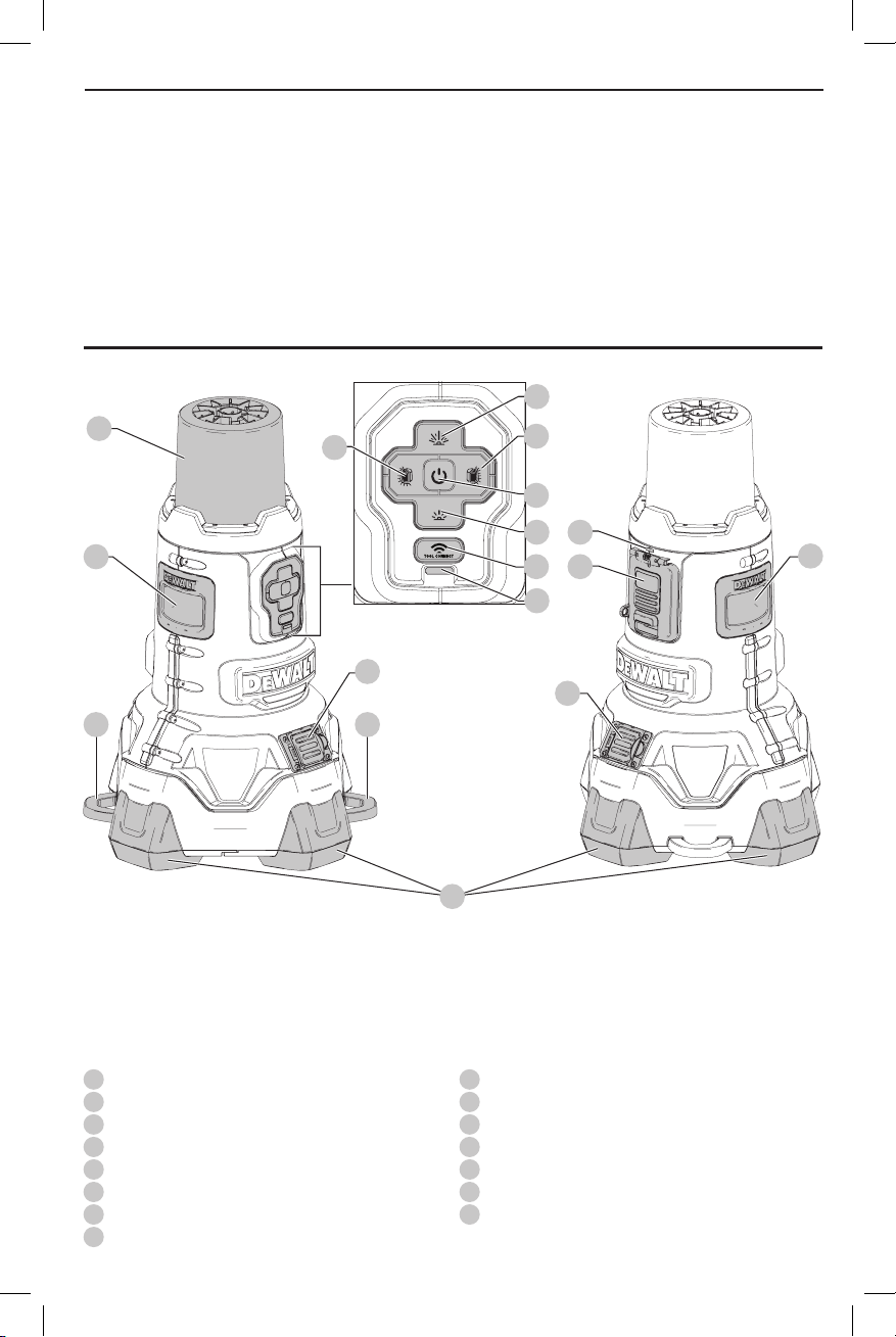
Fig. A
1
12
10
3
5
9
10
11
6
2
15
4
14
7
8
13
12
1
Lens
2
Power on/off button
3
Brightness up button
4
Brightness down button
5
Left half on/off button
6
Right half on/off button
7
Tool Connect™ button
8
Tool Connect™ indicator
9
AC plug
10
Security tab
11
Feet
12
Handle
13
AC outlet
14
Battery door
15
Charge indicator
1

ENGLISH
DeWALT
DeWALT
DeWALT
IF YOU HAVE ANY QUESTIONS OR COMMENTS
ABOUT THIS OR ANY
FREE AT: 1–800–4-
TOOL, CALL US TOLL
(1–800–433–9258).
Important Safety
Instructions
WARNING! When using the area
light, basic precautions should always be followed,
including the following:
a ) Read all the instructions before using the area light.
b ) To reduce the risk of injury, close supervision is
necessary when an area light is used near children.
c ) To disconnect, turn all controls to the OFF position,
then remove plug from outlet.
d ) Do not unplug by pulling on cord. To unplug, grasp
the plug, not the cord.
e ) Unplug from outlet when not in use and before
servicing or cleaning.
f ) Do not operate any area light with a damaged
cord or plug, or after the area light has received
a sharp blow, malfunctions or is dropped or
damaged in any manner. Return area light to the
nearest authorized service facility for examination,
repair, or electrical or mechanical adjustment.
g ) To reduce the risk of electrical shock, do not put
area light in water or other liquid. Do not place
or store area light where it can fall or be pulled into a
tub or sink.
h ) Connect to a properly grounded outlet only. Refer
to Grounding Instructions.
i ) Only use attachments recommended or sold by
themanufacturer.
j ) Risk of electric shock. Do not expose to rain. Store
indoors.
SAVE THESE
INSTRUCTIONS
Specific Safety Rules for Area Lights
WARNING: Fire hazard. Do not operate area light
near flammable liquids or in gaseous or explosive
atmospheres. Internal sparks may ignite fumes
causing personal injury.
• Do not submerge area light in any liquid.
• The area light is intended for commercial and
householduse.
• Before using battery and area light/charger, read all
instructions and cautionary markings on area light/
charger and battery pack.
• Store the area light indoors when not in use. Keep out of
reach of children.
• DO NOT attempt to charge the battery pack with any
chargers other than the ones in this manual. The area
2
light/charger and battery pack are specifically designed to
work together.
• Make sure extension cord is located so that it will not
be stepped on, tripped over, or otherwise subjected to
damage or stress.
• Use only a proper extension cord that is necessary to
operate the DCL070 area light on AC power (refer to
Use of Extension Cords with Area Light). Use of an
improper extension cord could result in risk of fire, electric
shock, or electrocution.
• A proper extension cord will be marked with the
suffix letter "W" and with a tag stating "Suitable for
Use with Outdoor Appliances."
• Place the area light away from any heat source.
• Do not disassemble area light. Take it to an authorized
service center when service or repair is required. Incorrect
reassembly may result in a risk of electric shock,
electrocution or fire.
• Disconnect the area light/charger from the outlet before
attempting any cleaning. This will reduce the risk of
electric shock. Removing the battery pack will not reduce
this risk.
• The DCL070 area light/charger is designed to operate on
120 Volts, 60 Hz AC or on direct current (DC) through fully
charged
battery packs. Do not use any other voltage.
• Use type SJW, SJOW, SJTW, SJTOW, SW, SOW, STW and
STOW cord when operating the area light on AC power.
• Do not stack more than 3 area lights. When using casters,
do not stack more than 2 area lights.
• Secure the area light in upright position while transporting.
WARNING: To reduce the risk of fire, do not place
anything on top of the lens during or after operation
of the light.
WARNING: Do not place the area light in a position
which may cause anyone to intentionally or
unintentionally stare into the area light. Serious eye
injury could result.
The label on your tool may include the following symbols. The
symbols and their definitions are asfollows:
V ......................... volts
Hz ....................... hertz
min ..................... minutes
or DC ......direct current
...................... Class I Construction
…/min .............. per minute
BPM .................... beats per minute
IPM ..................... impacts per minute
RPM .................... revolutions per
sfpm ................... surface feet per
SPM .................... strokes per minute
A ......................... amperes
W ........................ watts
or AC ........... alternating current
20V Max* or FLEXVOLT™ lithium-ion
or AC/DC .... alternating or
...................... Class II
(grounded)
minute
minute
no ....................... no load speed
n ......................... rated speed
...................... earthing terminal
..................... safety alert symbol
..................... visible radiation
..................... wear respiratory
..................... wear eye
..................... wear hearing
..................... read all
direct current
Construction
(double insulated)
protection
protection
protection
documentation

Grounding Instructions
In the event of malfunction or breakdown, grounding
provides a path of least resistance for electric current to
reduce the risk of electric shock. The area light must be
connected to a cord having an equipment-grounding
conductor and a grounding plug. The plug must be
plugged into an appropriate outlet that is properly
installed and grounded in accordance with all local codes
andordinances.
DANGER: Improper connection of the equipment
grounding conductor can result in a risk of electric
shock. The conductor with insulation having an outer
surface that is green with or without yellow stripes
is the equipment grounding conductor. If repair or
replacement of the cord or plug is necessary, do not
connect the equipment-grounding conductor to a
live terminal. Check with a qualified electrician or
serviceman if the grounding instructions are not
completely understood, or if in doubt as to whether
the area light is properly grounded. Do not modify the
plug connected to the area light—if it will not fit the
outlet, have a proper outlet installed by a qualified
electrician.
For grounded, cord-connected area
lights rated less than 15A and intended
for use on a nominal 120V supply circuit
The area light is for use on a nominal 120V circuit, and
should be connected to a grounding plug that looks like
the plug illustrated in sketch a. A temporary adaptor, which
looks like the adaptor illustrated in sketch b, may be used
to connect this plug to a 2-pole receptacle as shown in
sketch b if a properly grounded outlet is not available. The
temporary adaptor should be used only until a properly
grounded outlet can be installed by a qualified electrician.
The green colored rigid ear, lug, and the like, extending
from the adaptor must be connected to a permanent
ground such as a properly grounded outlet box cover.
Whenever the adaptor is used, it must be held in place by
the metal screw.
a
GROUNDING PIN
GROUNDED
OUTLET
BOX
b
ADAPTER
Use of Extension Cords with Area light
Only use a grounded extension cord that is rated at least
12amps and has a third-wire ground.
When a long extension cord is used to connect a area light
or tool, a voltage drop occurs. The longer the cord, the
greater the voltage drop. This results in less voltage being
supplied to the area light or tool and increases the amount
of current (amp) draw or reduces performance. A heavier
cord with a larger wire size will reduce the voltage drop. Be
ENGLISH
sure to choose a cord that will supply enough voltage to
operate your tool and/or area light.
WARNING: Risk of electric shock. Keep extension cord
connection dry and off the ground.
WARNING: Keep electrical cords in good condition.
Do not use worn, bare, or frayed cords because they
can cause electrical shock.
WARNING: Operating equipment at low voltage
can cause it to overheat. Using an excessively long
extension cord can cause the cord to overheat.
For more information about extension cord size
requirements, refer to the Minimum Gauge for Cord Sets
chart found under Important Safety Instructions for the
Area Light/Charger.
Wireless Certifications and Safety
Information
• When traveling on airlines, be sure to comply with the
airline restrictions on usage of personal electronic devices
and Bluetooth®.
• The out of range alert feature has been designed to act
as an aid to warn against products getting misplaced or
stolen. It is not a security system.
• The connectivity range is up to 100 feet (30.5 meters)
depending on environment and location.
• The shortwave radio frequency signals of a Bluetooth®
device may impair the operation of other electronic and
medical devices (such as pacemakers or hearing aids).
• This device is CAN ICES-3(B)/NMB-3(B) compliant.
• This device complies with Part 15 of the FCC rules and
Industry Canada License-exempt RSS standard(s).
Operation is subject to the following two conditions:
ʵ This device may not cause harmful interference, and
ʵ This device must accept any interference
received, including interference that may cause
undesiredoperation.
NOTE: This equipment has been tested and found to comply
with the limits for a Class B digital device, pursuant to Part
15 of the FCC Rules. These limits are designed to provide
reasonable protection against harmful interference in a
residential installation. This equipment generates, uses and
can radiate radio frequency energy and, if not installed and
used in accordance with the instructions, may cause harmful
interference to radio communications. However, there is no
guarantee that interference will not occur in a particular
installation. If this equipment does cause harmful interference
to radio or television reception, which can be determined by
turning the equipment off and on, the user is encouraged
to try to correct the interference by one or more of the
followingmeasures:
ʵ Reorient or relocate the receiving antenna.
ʵ Increase the separation between the equipment and
adaptor.
ʵ Connect the equipment into an outlet on a circuit
different from that to which the adaptor is connected.
ʵ Consult the dealer or an experienced radio/TV
technician for help.
3

ENGLISH
DeWALT
DeWALT
DeWALT
DeWALT
DeWALT
• Under Industry Canada regulations, this radio transmitter
may only operate using an antenna of a type and
maximum (or lesser) gain approved for the transmitter by
Industry Canada. To reduce potential radio interference
to other users, the antenna type and its gain should
be so chosen that the equivalent isotropically radiated
(e.i.r.p.) is not more than that necessary for successful
communication.
• To comply with FCC and Industry Canada RF radiation
exposure limits for general population, the antenna used
for this device must not be co-located or operating in
conjunction with any other antenna or transmitter.
• Changes or modifications to this equipment not expressly
approved by the manufacturer could void the user’s
authority to operate the device.
NOTE: The Bluetooth® word mark and logos are registered
trademarks owned by the Bluetooth®, SIG, Inc. and any use of
such marks by
trade names are those of their respective owners.
This product complies with these standards when operated
with a 6 foot or shorter extension cord.
is under license. Other trademarks and
BATTERIES AND CHARGERS
The area light/charger operates using a
and Flexvolt™ lithium-ion battery pack.
NOTE: The DCL070 area light/charger is also designed to
operate on 120 Volts, 60 Hz AC.
The battery pack is not fully charged out of the carton.
Before using the battery pack and charger, read the
safety instructions below and then follow charging
proceduresoutlined. When ordering replacement battery
packs, be sure to include the catalog number andvoltage.
Your tool uses a
instructions before using your charger. Consult the chart
at the end of this manual for compatibility of chargers and
batterypacks.
charger. Be sure to read all safety
READ ALL INSTRUCTIONS
20V Max*
Important Safety Instructions for All
Battery Packs
WARNING: Read all safety warnings and all
instructions for the battery pack and area light/
charger. Failure to follow the warnings and
instructions may result in electric shock, fire and/
or serious injury.
• Do not charge or use the battery pack in explosive
atmospheres, such as in the presence of flammable
liquids, gases or dust. Inserting or removing the battery
pack from the area light/charger may ignite the dust
orfumes.
• NEVER force the battery pack into the area light/
charger. DO NOT modify the battery pack in any way
to fit into a non-compatible charger as battery pack
may rupture causing serious personal injury. Consult
the chart at the end of this manual for compatibility of
batteries andchargers.
• Charge the battery packs only in designated
• DO NOT splash or immerse in water or otherliquids.
• Do not store or use the tool and battery pack in
• If battery contents come into contact with the skin,
• Contents of opened battery cells may cause
chargers.
locations where the temperature may reach or
exceed 104°F (40°C) (such as outside sheds or metal
buildings in summer). For best life, store battery packs in
a cool, drylocation.
Do not incinerate the battery pack even if it is
severely damaged or is completely worn out. The
battery pack can explode in a fire. Toxic fumes and
materials are created when lithium ion battery packs
areburned.
immediately wash area with mild soap and water. If
battery liquid gets into the eye, rinse water over the open
eye for 15 minutes or until irritation ceases. If medical
attention is needed, the battery electrolyte is composed of
a mixture of liquid organic carbonates and lithiumsalts.
respiratory irritation. Provide fresh air. If symptoms
persist, seek medicalattention.
WARNING: Burn hazard. Battery liquid may be
flammable if exposed to spark orflame.
WARNING: Fire hazard. Never attempt to open the
battery pack for any reason. If the battery pack case
is cracked or damaged, do not insert into the charger.
Do not crush, drop or damage the battery pack. Do
not use a battery pack or charger that has received a
sharp blow, been dropped, run over or damaged in
any way (e.g., pierced with a nail, hit with a hammer,
stepped on). Damaged battery packs should be
returned to the service center forrecycling.
Transportation
WARNING: Fire hazard. Do not store or carry the
battery pack so that metal objects can contact
exposed battery terminals. For example, do
not place the battery pack in aprons, pockets, tool
boxes, product kit boxes, drawers, etc., with loose
nails, screws, keys, etc. Transporting batteries
can possibly cause fires if the battery terminals
inadvertently come in contact with conductive
materials such as keys, coins, hand tools and the
like. The US Department of Transportation Hazardous
Material Regulations (HMR) actually prohibit
transporting batteries in commerce or on airplanes in
carry-on baggage UNLESS they are properly protected
from short circuits. So when transporting individual
battery packs, make sure that the battery terminals
are protected and well insulated from materials that
could contact them and cause a short circuit.
Shipping the
The DeWALT FLEXVOLT™ battery has two modes: Use and
Shipping.
FLEXVOLT™ Battery
4
Use Mode: When the FLEXVOLT™ battery stands alone or is
DeWALT
DeWALT
DeWALT
DeWALT
DeWALT
DeWALT
in a DeWALT 20V Max* product, it will operate as a 20V Max*
battery. When the FLEXVOLT™ battery is in a 60V Max* or a
120V Max* (two 60V Max* batteries) product, it will operate
as a 60V Max* battery.
Shipping Mode: When the
cap is attached to the
FLEXVOLT™ battery, the
battery is in Shipping
Mode. Strings of cells are
electrically disconnected within the pack resulting in three
batteries with a lower Watt hour (Wh) rating as compared to
one battery with a higher Watt hour rating. This increased
quantity of three batteries with the lower Watt hour rating
can exempt the pack from certain shipping regulations that
are imposed upon the higher Watt hour batteries.
The battery label indicates two Watt hour ratings (see
example). Depending on how the battery is shipped, the
appropriate Watt hour rating must be used to determine
the applicable shipping requirements. If utilizing the
shipping cap, the pack will be considered 3 batteries at
the Watt hour rating indicated for “Shipping”. If shipping
without the cap or in a tool, the pack will be considered one
battery at the Watt hour rating indicated next to “Use”.
Example of Use and Shipping Label Marking
USE: 120 Wh Shipping: 3 x 40 Wh
For example, Shipping Wh rating might indicate 3 x 40 Wh,
meaning 3 batteries of 40 Watt hours each. The Use Wh
rating might indicate 120 Wh (1 battery implied).
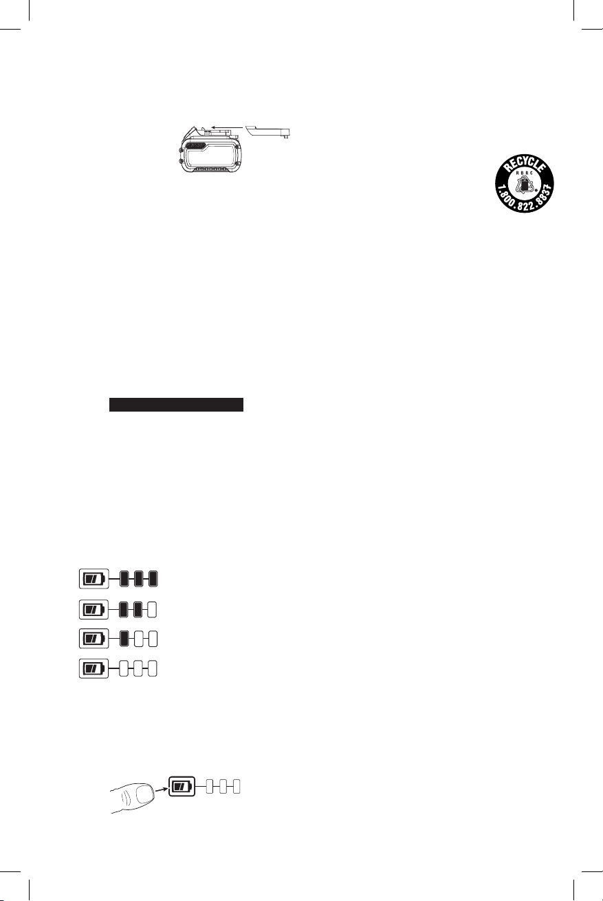
Fuel Gauge Battery Packs (Fig. B)
Some
consists of three green LED lights that indicate the level of
charge remaining in the batterypack.
The fuel gauge is an indication of approximate levels of
charge remaining in the battery pack according to the
followingindicators:
To actuate the fuel gauge, press and hold the fuel gauge
button. A combination of the three green LED lights will
illuminate designating the level of charge left. When the
level of charge in the battery is below the usable limit, the
fuel gauge will not illuminate and the battery will need to
berecharged.
NOTE: The fuel gauge is only an indication of the charge left
on the battery pack. It does not indicate tool functionality
battery packs include a fuel gauge which
75–100% charged
51–74% charged
< 50% charged
Pack needs to be charged
Fig. B
ENGLISH
and is subject to variation based on product components,
temperature and end-userapplication.
For more information regarding fuel gauge battery packs,
please contact call 1-800-4visit our website www.dewalt.com.
(1-800-433-9258) or
The RBRC® Seal
The RBRC® (Rechargeable Battery
Recycling Corporation) Seal on the nickel
cadmium, nickel metal hydride or lithiumion batteries (or battery packs) indicates
that the costs to recycle these batteries
(or battery packs) at the end of their useful life have already
been paid by
spent nickel cadmium, nickel metal hydride or lithium-ion
batteries in the trash or municipal solid waste stream and
the Call2Recycle® program provides an environmentally
consciousalternative.
Call 2 Recycle, Inc., in cooperation with
battery users, has established the program in the United
States and Canada to facilitate the collection of spent nickel
cadmium, nickel metal hydride or lithium-ion batteries. Help
protect our environment and conserve natural resources by
returning the spent nickel cadmium, nickel metal hydride
or lithium-ion batteries to an authorized
center or to your local retailer for recycling. You may also
contact your local recycling center for information on
where to drop off the spent battery. RBRC® is a registered
trademark of Call 2 Recycle,Inc.
. In some areas, it is illegal to place
and other
service
Important Safety Instructions for the
Area Light/Charger
WARNING: Read all safety warnings and all
instructions for the battery pack and area light/
charger. Failure to follow the warnings and
instructions may result in electric shock, fire and/
or serious injury.
• The area light/charger is not intended for any
uses other than professional workspace lighting
and charging
rechargeable batteries. Any other uses may result in risk
of fire, electric shock orelectrocution.
• Do not expose the area light/charger to rain
orsnow.
• Pull by the plug rather than the cord when
disconnecting the area light/charger. This will reduce
the risk of damage to the electric plug andcord.
• Make sure that the extension cord is located so that
it will not be stepped on, tripped over or otherwise
subjected to damage orstress.
• When operating the area light/charger outdoors,
always provide a dry location and use an extension
cord suitable for outdoor use. Use of a cord suitable for
outdoor use reduces the risk of electricshock.
• An extension cord must have adequate wire size
(AWG or American Wire Gauge) for safety. The smaller
the gauge number of the wire, the greater the capacity
of the cable, that is, 16 gauge has more capacity than 18
20V Max* and Flexvolt™
5
ENGLISH
DeWALT
gauge. An undersized cord will cause a drop in line voltage
resulting in loss of power and overheating. When using
more than one extension to make up the total length,
be sure each individual extension contains at least the
minimum wire size. The following table shows the correct
size to use depending on cord length and nameplate
ampere rating, and the voltage drop caused by the use of
extension cords, given different electtical loads. If in doubt,
use the next heavier gauge. The lower the gauge number,
the heavier thecord.
Minimum Gauge for Cord Sets
Volts
120 V 25 (7.6) 50 (15.2) 100 (30.5) 150 (45.7)
240 V 50 (15.2) 100 (30.5) 200 (61.0) 300 (91.4)
Ampere Rating
More
Not
Than
More
Than
0 6 18 16 16 14
6 10 18 16 14 12
10 12 16 16 14 12
12 16 14 12 Not Recommended
• Do not place any object on top of the area light/
charger nor place the area light/charger on a soft
surface that might block the ventilation slots and
result in excessive internal heat. Place the area light/
charger in a position away from any heat source. The
area light is ventilated through slots in the top of the
LEDlens.
• Do not operate the area light/charger with a
damaged cord orplug.
• Do not operate the area light/charger if it has
received a sharp blow, been dropped or otherwise
damaged in any way. Take it to an authorized
servicecenter.
• Do not disassemble the area light/charger; take it to
an authorized service center when service or repair
is required. Incorrect reassembly may result in a risk of
electric shock, electrocution orfire.
• Disconnect the area light/charger from the outlet
before attempting any cleaning. This will reduce the
risk of electric shock. Removing the battery pack will not
reduce thisrisk.
• NEVER attempt to connect more than 4 area lights together.
• The area light/charger is designed to operate on
standard 120V household electrical power. Do not
attempt to use it on any other voltage. This does not
apply to the vehicularcharger.
WARNING: Shock hazard. Do not allow any liquid
to get inside the area light/charger. Electric shock
mayresult.
WARNING: Burn hazard. Do not submerge the
battery pack in any liquid or allow any liquid to
enter the battery pack. Never attempt to open the
battery pack for any reason. If the plastic housing of
the battery pack breaks or cracks, return to a service
center for recycling.
6
Total Length of Cord in Feet
(meters)
American Wire Gauge
CAUTION: Burn hazard. To reduce the risk of injury,
charge only
Other types of batteries may overheat and burst
resulting in personal injury and propertydamage.
NOTICE: Under certain conditions, with the area
light/charger plugged into its power supply, the area
light/charger can be shorted by foreign material.
Foreign materials of a conductive nature, such as,
but not limited to, grinding dust, metal chips, steel
wool, aluminum foil or any buildup of metallic
particles, should be kept away from the area light/
charger cavities. Unplug the area light/charger before
attempting toclean.
rechargeable battery packs.
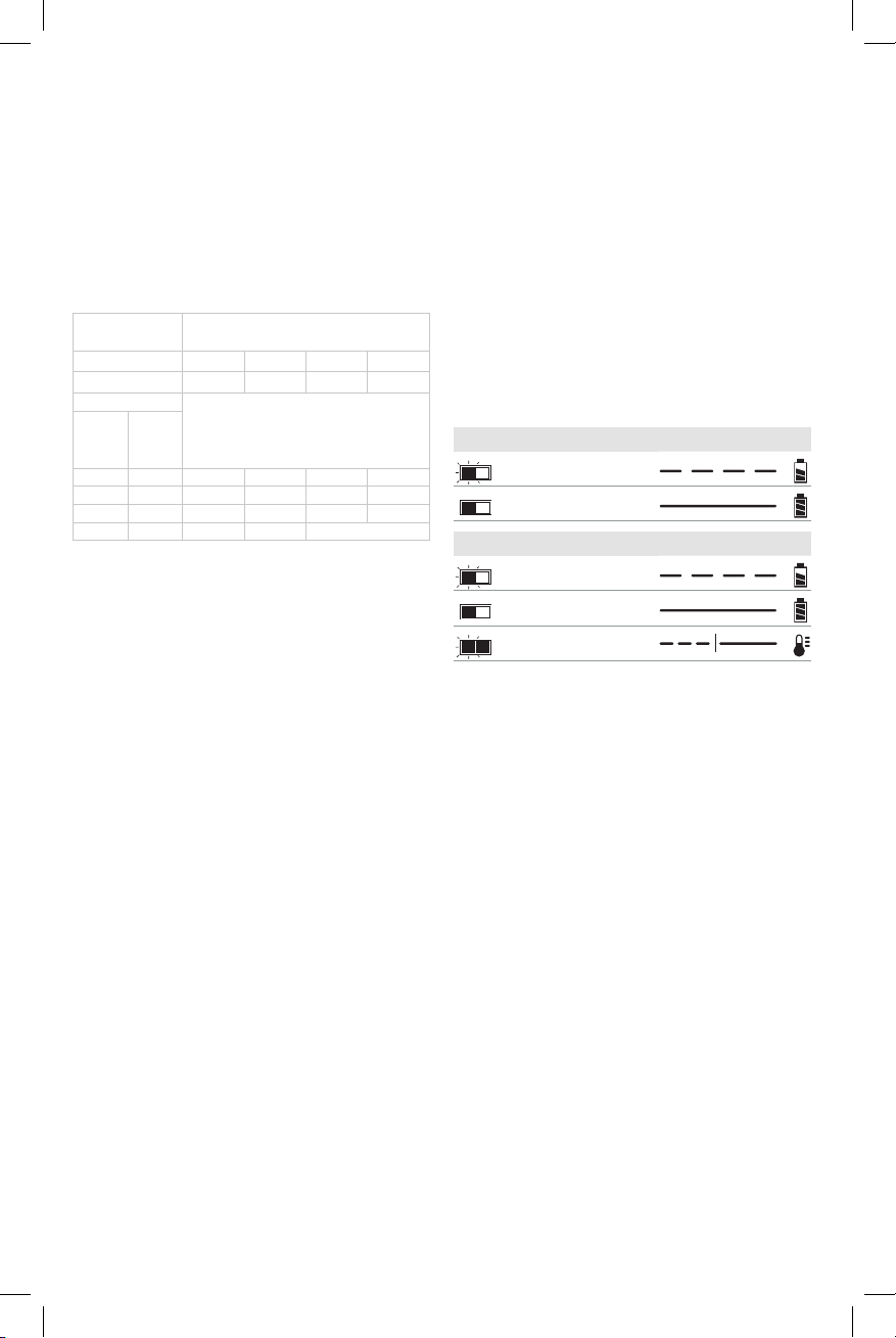
Charging Operation
Refer to the indicators below for the charge status of the
battery pack.
Charging Indicators
Charging
Fully Charged
DCB107, DCB112, DCB113, DCB115, DCB118, DCB132
Charging
Fully Charged
Hot/Cold Pack Delay*
* DCB107, DCB112, DCB113, DCB115, DCB118, DCB132:
The red light will continue to blink, but a yellow indicator
light will be illuminated during this operation. Once the
battery pack has reached an appropriate temperature, the
yellow light will turn off and the charger will resume the
charging procedure.
The area light/charger will not charge a faulty battery pack.
The area light/charger will indicate faulty battery pack by
refusing to light or by displaying a problem pack or charger
blink pattern.
NOTE: This could also mean a problem with a area light/
charger.
If the area light/charger indicates a problem, take the area
light/charger and battery pack to be tested at an authorized
service center.
Hot/Cold Pack Delay
DCB107, DCB112, DCB113, DCB115, DCB118, DCB132
When the charger detects a battery pack that is too hot
or too cold, it automatically starts a Hot/Cold Pack Delay,
suspending charging until the battery pack has reached an
appropriate temperature. The charger then automatically
switches to the pack charging mode. This feature ensures
maximum battery pack life.
A cold battery pack will charge at a slower rate than a warm
battery pack. The battery pack will charge at that slower rate
throughout the entire charging cycle and will not return to
maximum charge rate even if the battery pack warms.

The DCB118 charger is equipped with an internal fan
DeWALT
designed to cool the battery pack. The fan will turn on
automatically when the battery pack needs to be cooled.
Never operate the charger if the fan does not operate
properly or if ventilation slots are blocked. Do not permit
foreign objects to enter the interior of the charger.
Electronic Protection System
Li-Ion tools are designed with an Electronic Protection
System that will protect the battery pack against
overloading, overheating or deep discharge.
The tool will automatically turn off if the Electronic
Protection System engages. If this occurs, place the lithiumion battery pack on the charger until it is fully charged.
Wall Mounting
DCB107, DCB112, DCB113, DCB115, DCB118, DCB132
These chargers are designed to be wall mountable or to
sit upright on a table or work surface. If wall mounting,
locate the charger within reach of an electrical outlet,
and away from a corner or other obstructions which may
impede air flow. Use the back of the charger as a template
for the location of the mounting screws on the wall. Mount
the charger securely using drywall screws (purchased
separately) at least 1" (25.4 mm) long, with a screw head
diameter of 0.28–0.35" (7–9mm), screwed into wood to an
optimal depth leaving approximately 7/32" (5.5 mm) of the
screw exposed. Align the slots on the back of the charger
with the exposed screws and fully engage them in the slots..
Charger Cleaning Instructions
DCB107, DCB112, DCB113, DCB115, DCB118, DCB132
WARNING: Shock hazard. Disconnect the charger
from the AC outlet before cleaning. Dirt and grease
may be removed from the exterior of the charger using
a cloth or soft non-metallic brush. Do not use water or
any cleaning solutions.
Important Charging Notes
1. Longest life and best performance can be obtained if
the battery pack is charged when the air temperature is
between 65°F and 75°F (18° – 24°C). DO NOT charge
the battery pack in an air temperature below +40°F
(+4.5°C), or above +104°F (+40°C). This is important
and will prevent serious damage to the battery pack.
2. The area light/charger and battery pack may become
warm to the touch while charging. This is a normal
condition, and does not indicate a problem. To
facilitate the cooling of the battery pack after use,
avoid placing the area light/charger or battery pack
in a warm environment such as in a metal shed or an
uninsulatedtrailer.
3. If the battery pack does not charge properly:
a. Check operation of receptacle by plugging in a lamp
or other appliance;
b. Check to see if receptacle is connected to a light
switch which turns power off when you turn out
thelights;
ENGLISH
c. Move the area light/charger and battery pack to a
location where the surrounding air temperature is
approximately 65°F – 75°F (18° – 24°C);
d. If charging problems persist, take the area light/
charger and battery pack to your local service center.
4. The battery pack should be recharged when it fails to
produce sufficient power on jobs which were easily
done previously. DO NOT CONTINUE to use under these
conditions. Follow the charging procedure. You may
also charge a partially used pack whenever you desire
with no adverse effect on the battery pack.
5. Foreign materials of a conductive nature such as, but
not limited to, grinding dust, metal chips, steel wool,
aluminum foil, or any buildup of metallic particles
should be kept away from area light/charger cavities.
Unplug the area light/charger before attempting
toclean.
6. Do not freeze or immerse the area light/charger in water
or any other liquid.
WARNING: Shock hazard. Don’t allow any liquid
to get inside the area light/charger. Electric shock
mayresult.
WARNING: Burn hazard. Do not submerge the
battery pack in any liquid or allow any liquid to
enter the battery pack. Never attempt to open the
battery pack for any reason. If the plastic housing of
the battery pack breaks or cracks, return to a service
center for recycling.
Storage Recommendations
1. Store the area light/charger indoors.
2. The best storage place is one that is cool and dry, away
from direct sunlight and excess heat or cold.
3. For long storage, it is recommended to store a fully
charged battery pack in a cool dry place out of the area
light/charger for optimal results.
NOTE: Battery packs should not be stored completely
depleted of charge. The battery pack will need to be
recharged before use.
SAVE THESE INSTRUCTIONS FOR
FUTURE USE
COMPONENTS (FIG. A)
WARNING: Never modify the power tool or any part
of it. Damage or personal injury couldresult.
Refer to Figure A at the beginning of this manual for a
complete list ofcomponents.
INTENDED USE
This area light is designed for professional workspace
lighting and charging
rechargeable batteries.
DO NOT use in presence of flammable liquids or gases.
DO NOT let children come into contact with the tool.
Supervision is required when inexperienced operators use
this tool.
20V Max* and Flexvolt™
7
ENGLISH
DeWALT
DeWALT
DeWALT
DeWALT
DeWALT
DeWALT
DeWALT
DeWALT
OPERATION
WARNING: To reduce the risk of serious personal
injury, turn light off, remove battery pack and
disconnect from the AC outlet before making any
adjustments, removing/installing attachments
or accessories, and before cleaning.
WARNING: Do not cover the lens during
operation.
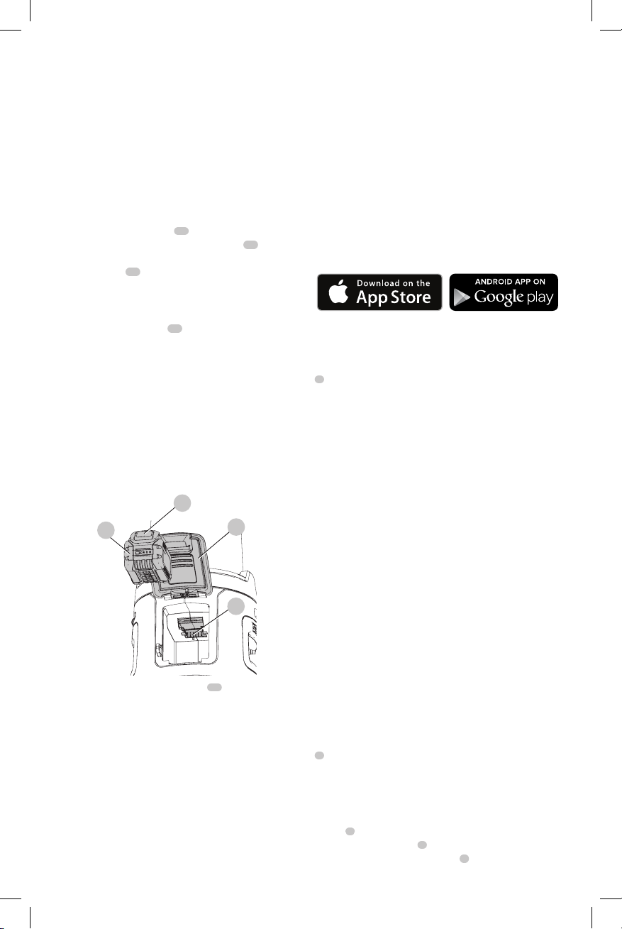
Installing and Removing Battery Packs
(Fig. D)
1. To install the battery pack
charger, lift the battery compartment door
battery pack with the rails inside the area light's battery
compartment
is firmly seated. Ensure that it does not disengage, then
close the door.
2. To remove the battery pack from the area light/charger,
press the release button
firmly pull the battery pack out.
19
17
into the area light/
and slide it in until the battery pack
18
on the battery pack and
Charging a Battery in the Area Light/
Charger (Fig. D)
1. Attach an extension cord to the area light, then plug
the area light/charger into an appropriate outlet before
inserting battery pack.
NOTE: The area light/charger will not charge a battery
unless the light is plugged into an AC outlet.
2. To install the battery pack, refer to Installing and
Removing Battery Packs.
Fig. D
17
3. The red (charging) indicator light (
continuously indicating that the charging process
hasstarted.
4. The completion of charge will be indicated by the red
(charging) indicator light remaining ON continuously.
The battery pack is fully charged and may be used at
this time or left in the area light/charger.
NOTE: To ensure maximum performance and life of lithiumion battery packs, charge the battery pack fully before
firstuse.
This area light is capable of connecting with mobile
devices that support Bluetooth® Smart (or Bluetooth® 4.0)
8
Tool Connect™
18
15
, Fig.A) will blink
14
19
14
, align the
technology. (To see if your mobile device is compatible,
visit: http://www.bluetooth.com/Pages/Bluetooth-Smart-
Devices-List.aspx)
Tool Connect™ is an optional application for your
smart device (such as a smart phone or tablet) that can
connect and control your area light.
NOTE: The Bluetooth® word mark and logos are registered
trademarks owned by the Bluetooth®, SIG, Inc. and any use
of such marks by
and trade names are those of their respective owners.
NOTE: The Tool Connect™ App is governed by separate
terms and conditions available for viewing through the
mobile application.
Step 1: Download the
applicationat:
Step 2: Follow the instructions in the app to create your
Tool Connect™ account.
Step 3: Connect your area light with the
Connect™ app first by pressing the Tool Connect™ button
7
on the front of the light until it begins to blink. Then go
to the Home screen of the app and select "+ Tool." The area
light can only be connected to one Tool Connect™ account
at a time.
Step 4: Once the connection is established, you will be
prompted to give the product an individual name as well as
confirm that you would like to register the product on your
.com account.
CAUTION: When using the scheduler, ensure
the illuminated area is free of personnel before a
scheduled turn off.
For more information on DeWALT Tool Connect™
functionality and features, please call 1–800–4(1–800–433–9258), visit www.
FAQ page and help screens located inside the mobile
application.
is under license. Other trademarks
Tool Connect™
.com or view the
Using and Controlling the Area Light
(Fig. A)
NOTE: For best results, make sure your battery pack is
fullycharged. Refer to Charging a Battery in the Area
Light/Charger.
On/Off Button (Fig. A)
CAUTION: Do not stare into area light lens.
Serious eye injury could result.
To turn both halves of the light on, press the on/off button
2
. To turn them both off, press the on/off button again.
Light Levels
The area light has 10 brightness levels. Maximum brightness
for DC operation is 3000 lm. Maximum brightness for AC
operation is 7000 lm. You can press the brightness up
3
button
to increase the brightness level or press the
brightness down button
and hold the brightness up button
4
to lower the brightness. Press
3
to go directly to
Tool

maximum brightness. Press and hold the brightness down
DeWALT
DeWALT
DeWALT
DeWALT
DeWALT
DeWALT
DeWALT
DeWALT
4
button
to go directly to minimum brightness.
Pressing the brightness up button
brightness will go directly to minimum brightness.
Pressing the brightness down button
brightness will go directly to maximum brightness.
Light Direction
To turn the left half of the light on or off, press the left light
on/off button
press the right light on/off button
5
. To turn the right half of the light on or off,
3
while at maximum
4
while at minimum
6
.
Low Battery Indicator
As the battery nears a fully discharged state, the light will
blink twice and then dim, dropping the brightness of the
light below the normal level. The light will continue to blink
twice every 45 seconds until the battery is fully discharged
at which time the light will turn off. Indication time will vary
based on battery pack capacity.
WARNING: Stop work and replace the battery or
connect the area light to AC when this occurs.
AC Outlet/AC Plug (Fig. A)
An extension cord can be plugged into the AC plug
then into a wall outlet to power the area light and charge
the battery. An AC outlet is available to connect extension
cords to additional lights or for powering additional tools or
appliances.
NOTE: The AC outlet cannot be controlled by the Tool
Connect™ app.
WARNING: Do not connect devices drawing more
than 10 amps.
WARNING: Do not connect more than 4 area
lightstogether.
CAUTION: The area light's AC outlet is "live" when
the area light is plugged into a wall outlet. The AC
outlet is not controlled by buttons or by the Tool
Connect™app.
9
Securing the Area Light
Two security tabs
light to lock it with a chain or to keep multiple area lights
secured together.
10
are available on the base of the area
Moving the Area Light
Two handles
light. The feet
standard 3" (76 mm) diameter casters with 3/8-16 UNC
threaded studs (1-3/4" [45 mm] maximum stud length) with
a minimum 100 lb weight capacity. At least one caster must
be of a locking type. Accessory
on www.dewalt.com.
12
are provided for safely carrying your area
11
on the area light can accommodate four
casters are available
MAINTENANCE
WARNING: To reduce the risk of serious personal
injury, turn area light/charger off, remove
battery pack and disconnect from the AC outlet
before making any adjustments, removing/
ENGLISH
installing attachments or accessories, and
beforecleaning.
Cleaning
WARNING: Blow dirt and dust out of all air vents with
clean, dry air at least once a week. To minimize the risk
of eye injury, always wear ANSI Z87.1 approved eye
protection when performingthis.
WARNING: Never use solvents or other harsh
chemicals for cleaning the non-metallic parts of
the tool. These chemicals may weaken the plastic
materials used in these parts. Use a cloth dampened
only with water and mild soap. Do not clean this area
light with a water spray or the like; never immerse any
part of the area light in a liquid.
Accessories
WARNING: Since accessories, other than those
offered by
product, use of such accessories with this tool could be
hazardous. To reduce the risk of injury, only
recommended accessories should be used with
thisproduct.
Recommended accessories for use with your tool
are available at extra cost from your local dealer or
authorized service center. If you need assistance in
locating any accessory, please contact
Tool Co., 701East Joppa Road, Towson, MD 21286, call
1-800-4www.dewalt.com.
, have not been tested with this
(1-800-433-9258) or visit our website:
Industrial
Repairs
The battery pack is notserviceable.
WARNING: To assure product SAFETY and
RELIABILITY, repairs, maintenance and adjustment
(including brush inspection and replacement) should
be performed by a
or a
identical replacementparts.
authorized service center. Always use
factory service center
Register Online
Thank you for your purchase. Register your product nowfor:
• WARRANTY SERVICE: Registering your product will
help you obtain more efficient warranty service in case
there is a problem with yourproduct.
• CONFIRMATION OF OWNERSHIP: In case of
an insurance loss, such as fire, flood or theft, your
registration of ownership will serve as your proof
ofpurchase.
• FOR YOUR SAFETY: Registering your product will
allow us to contact you in the unlikely event a safety
notification is required under the Federal Consumer
SafetyAct.
Register online at www.dewalt.com/register.
Three Year Limited Warranty
will repair, without charge, any defects due to
faulty materials or workmanship for three years from the
date of purchase. This warranty does not cover part failure
9
 Loading...