

Page 1

ZGG81
ZGG81-N
ZERO GRAVITY
WEB GRINDER
USER MANUAL
Safety, Operation and Maintenance
© 2017 Stanley Black & Decker, Inc.
New Britain, CT 06053
U.S.A.
76531 8/2017 Ver. 1
Page 2

Page 3
TABLE OF CONTENTS
SAFETY SYMBOLS ...............................................................................................................................................4
SAFETY PRECAUTIONS .......................................................................................................................................5
TOOL STICKERS & TAGS .....................................................................................................................................6
WARNINGS / PINCH POINTS ...............................................................................................................................7
HOSE TYPES .........................................................................................................................................................8
HOSE RECOMMENDATIONS ...............................................................................................................................9
HTMA / EHTMA REQUIREMENTS ........................................................................................................................10
OPERATION ...........................................................................................................................................................11
TOOL PROTECTION & CARE ...............................................................................................................................13
TROUBLESHOOTING ...........................................................................................................................................14
SPECIFICATIONS ..................................................................................................................................................15
ZGG81/81-N MOTOR PARTS ILLUSTRATION .....................................................................................................16
ZGG81/81-N MOTOR/BEARING HOUSING PARTS LIST ....................................................................................17
ZGG81/81-N QUAD ARM ASSEMBLY ILLUSTRATION ........................................................................................18
ZGG81/81-N QUAD ARM ASSEMBLY PARTS LIST ..............................................................................................19
ZGG81/81-N CLAMP PARTS ILLUSTRATION ......................................................................................................20
ZGG81/81-N CLAMP PARTS LIST ........................................................................................................................21
ZGG81/81-N HANDLE PARTS ILLUSTRATION ....................................................................................................22
ZGG81/81-N MOTOR MOUNT ILLUSTRATION .................................................................................................... 23
ZGG81/81-N GUARD ILLUSTRATION & PARTS LIST ..........................................................................................24
ZGG81/81-N HOSE/COUPLERS ILLUSTRATION & PARTS LIST ........................................................................25
To ll out a product warranty validation form, and for information on your warranty,
visit www.stanleyhydraulics.com and select the Company tab > Warranty.
Note: The warranty validation record must be submitted to validate the warranty.
SERVICING: This manual contains safety, operation and routine maintenance instructions. Stanley Hydraulic Tools
recommends that servicing of hydraulic tools, other than routine maintenance, must be performed by an authorized
and certied dealer. Please read the following warning.
SERIOUS INJURY OR DEATH COULD RESULT FROM THE IMPROPER REPAIR OR
SERVICE OF THIS TOOL.
REPAIRS AND / OR SERVICE TO THIS TOOL MUST ONLY BE DONE BY AN
AUTHORIZED AND CERTIFIED DEALER.
For the nearest certied dealer, call Stanley Hydraulic Tools at (503) 659-5660 and ask for a Customer Service Representative.
ZGG81 User Manual ◄ 3
Page 4

SAFETY SYMBOLS
Safety symbols and signal words, as shown below, are used to emphasize all operator, maintenance and repair
actions which, if not strictly followed, could result in a life-threatening situation, bodily injury or damage to equipment.
This is the safety alert symbol. It is used to alert you to potential personal injury
hazards. Obey all safety messages that follow this symbol to avoid possible
injury or death.
This safety alert and signal word indicate an imminently hazardous situation
which, if not avoided, will result in death or serious injury.
This safety alert and signal word indicate a potentially hazardous situation
which, if not avoided, could result in death or serious injury.
This safety alert and signal word indicate a potentially hazardous situation
which, if not avoided, could result in death or serious injury.
This signal word indicates a potentially hazardous situation which, if not avoided,
may result in property damage.
This signal word indicates a situation which, if not avoided, will result in damage
to the equipment.
This signal word indicates a situation which, if not avoided, may result in damage
to the equipment.
Always observe safety symbols. They are included for your safety and for the protection of the tool.
LOCAL SAFETY REGULATIONS
Enter any local safety regulations here. Keep these instructions in an area accessible to the operator and
maintenance personnel.
4 ► ZGG81 User Manual
Page 5

SAFETY PRECAUTIONS
Tool operators and maintenance personnel must always
comply with the safety precautions given in this manual
and on the stickers and tags attached to the tool and
hose.
These safety precautions are given for your safety.
Review them carefully before operating the tool and
before performing general maintenance or repairs.
Supervising personnel should develop additional
precautions relating to the specic work area and local
safety regulations. Place the added precautions in the
space provided in this manual.
The model ZGG81 Zero Gravity Grinder will provide
safe and dependable service if operated in accordance
with the instructions given in this manual. Read and
understand this manual and any stickers and tags
attached to the grinder and hose before operation.
Failure to do so could result in personal injury or
equipment damage.
• The operator must start in a work area without
bystanders. Flying debris can cause serious injury.
• Do not operate the tool unless thoroughly trained
or under the supervision of an instructor. Establish
a training program for all operators to ensure safe
operation.
• Always wear safety equipment such as eye
protection, ear protection, head protection,
respiratory protection and safety shoes at all times
when operating the tool. Use gloves if necessary.
• The operator must be familiar with all prohibited work
areas such as excessive slopes and dangerous
terrain conditions. Railway workers must follow all
FRA Federal/State Railroad Administration safety
regulations at all times.
• Do not inspect, clean or replace the grinding wheel
while the hydraulic power source is connected. Do
not inspect or clean the tool while the hydraulic
power source is connected. Accidental engagement
of the tool can cause serious injury.
• Always connect hoses to the tool hose couplers
before energizing the hydraulic power source. Be
sure all hose connections are tight and are in good
condition.
• Do not operate the tool at oil temperatures above
140 °F/60 °C. Operation at higher temperatures can
cause higher than normal temperatures at the tool,
which can result in operator discomfort.
• Do not operate the tool with the wheel guard
removed.
• Do not operate a damaged, improperly adjusted or
incompletely assembled grinder.
• Never wear loose clothing that can become
entangled in the working parts of the tool.
• Keep all parts of your body away from the rotating
wheel and pinch points. Long hair or loose clothing
can become drawn into rotating components.
• Keep the wheel off all surfaces when starting the
grinder.
• Do not use a wheel that is cracked, chipped or
otherwise damaged. Always inspect wheels for
possible damage before installation or use.
• Always use wheels that conform to the specications
given in “Grinding Wheel Safety” on page 6.
• Do not reverse grinding wheel rotation direction by
changing uid ow direction.
• Do not move the tool until the grinding wheel has
stopped rotating. Release the trigger if the power
supply has been interrupted.
• To avoid personal injury or equipment damage,
all tool repair, maintenance and service must only
be performed by authorized and properly trained
personnel.
• If the material being ground creates an emission of
dust and fumes, use personal protective devices.
• Never cock, jam or wedge the grinding wheel during
operation.
• Never cause sparks in the vicinity of ammable
materials or gases.
• Eye injury, cutting or severing of body parts is
possible if proper procedures are not followed.
• Warning: Use of this tool on certain materials during
grinding could generate dust potentially containing a
variety of hazardous substances such as asbestos,
silica or lead. Inhalation of dust containing these or
other hazardous substances could result in serious
injury, cancer or death. Protect yourself and those
around you. Research and understand the materials
you are grinding or cutting. Follow correct safety
procedures and comply with all applicable national,
state or provisional health and safety regulations
relating to them, including arranging for the safe
disposal of the materials by a qualied person.
ZGG81 User Manual ◄ 5
Page 6
SAFETY PRECAUTIONS
GRINDING WHEEL SAFETY
• Ensure that the grinding wheel is correctly mounted
and tightened before use.
• Operate the grinder at “no load” for 30 seconds in
a safe position and ensure there is no vibration or
other defects detected. If considerable vibration or
other defects are detected, stop operation of the tool
immediately and determine the cause. Do not use
the tool until the defect is corrected.
• If the grinder is dropped with an abrasive wheel
installed, the abrasive wheel should be examined
thoroughly before use.
• Only use abrasive wheels that comply with ANSI
B7.1:2010/ISO 525, 603.
TOOL STICKERS & TAGS
• Ensure that the maximum RPM operating speed of
the abrasive wheel is equal to, or greater than, the
rated shaft speed of the grinder.
• Ensure that the grinding wheel dimensions are
compatible with the grinder and that the grinding
wheel ts the shaft.
• Ensure that the thread type and size of the grinding
wheel exactly matches the thread type and size of
the shaft.
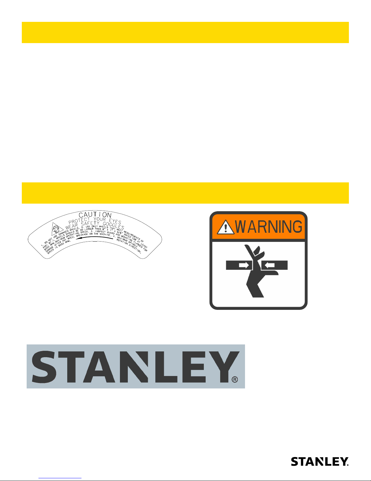
25414
CAUTION STICKER
74832
STANLEY LOGO STICKER
73038
PINCH POINT STICKER
6 ► ZGG81 User Manual
Page 7
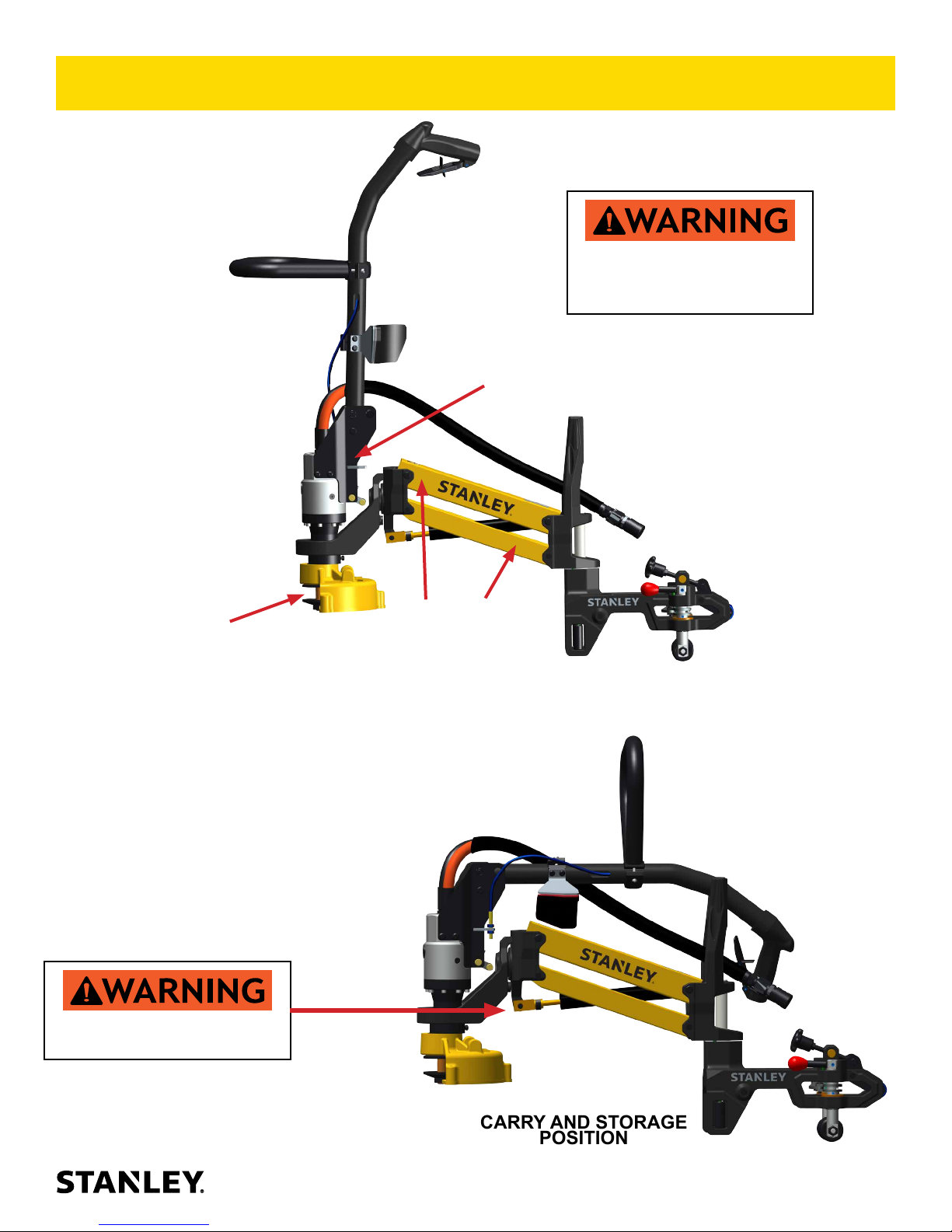
WARNINGS / PINCH POINTS
Keep all body parts clear of
potential pinch points or moving
parts indicated by the arrows
shown here.
CAUTION:
PINCH POINT
KEEP CLEAR OF
MOVING PARTS
Do not open or damage gas
spring, under high pressure.
CAUTION: PINCH POINT,
ARM FRAME COLLAPSES
WHEN MOVED
OPERATING POSITION
CARRY AND STORAGE
POSITION
ZGG81 User Manual ◄ 7
Page 8

HOSE TYPES
The rated working pressure of the hydraulic hose must be equal to or higher than the relief valve setting on the hydraulic system. There are three types of hydraulic hose that meet this requirement and are authorized for use with
Stanley Hydraulic Tools. They are:
Certied non-conductive — constructed of thermoplastic or synthetic rubber inner tube, synthetic ber braid
reinforcement, and weather resistant thermoplastic or synthetic rubber cover. Hose labeled certied non-
conductive is the only hose authorized for use near electrical conductors.
Wire-braided (conductive) — constructed of synthetic rubber inner tube, single or double wire braid reinforcement, and weather resistant synthetic rubber cover. This hose is conductive and must never be used near
electrical conductors.
Fabric-braided (not certied or labeled non-conductive) — constructed of thermoplastic or synthetic rubber inner tube, synthetic ber braid reinforcement, and weather resistant thermoplastic or synthetic rubber cover. This
hose is not certied non-conductive and must never be used near electrical conductors.
HOSE SAFETY TAGS
To help ensure your safety, the following DANGER tags are attached to all hose purchased from Stanley Hydraulic
Tools. DO NOT REMOVE THESE TAGS.
If the information on a tag is illegible because of wear or damage, replace the tag immediately. A new tag may be
obtained from your Stanley Distributor.
THE TAG SHOWN BELOW IS ATTACHED TO “CERTIFIED NON-CONDUCTIVE” HOSE
DANGER
1. FAILURE TO USE HYDRAULIC HOSE LABELED AND CERTIFIED AS NON-CONDUCTIVE
WHEN USING HYDRAULIC TOOLS ON OR NEAR ELECTRIC LINES MAY RESULT IN
DEATH OR SERIOUS INJURY.
FOR PROPER AND SAFE OPERATION MAKE SURE THAT YOU HAVE BEEN PROPERLY TRAINED IN CORRECT PROCEDURES REQUIRED FOR WORK ON OR AROUND
ELECTRIC LINES.
2. BEFORE USING HYDRAULIC HOSE LABELED AND CERTIFIED AS NON-CONDUCTIVE
ON OR NEAR ELECTRIC LINES. WIPE THE ENTIRE LENGTH OF THE HOSE AND FITTING WITH A CLEAN DRY ABSORBENT CLOTH TO REMOVE DIRT AND MOISTURE AND
TEST HOSE FOR MAXIMUM ALLOWABLE CURRENT LEAKAGE IN ACCORDANCE WITH
SAFETY DEPARTMENT INSTRUCTIONS.
DO NOT REMOVE THIS TAG
SEE OTHER SIDE
SIDE 1
3. DO NOT EXCEED HOSE WORKING PRESSURE OR ABUSE HOSE. IMPROPER USE
OR HANDLING OF HOSE COULD RESULT IN BURST OR OTHER HOSE FAILURE.
KEEP HOSE AS FAR AWAY AS POSSIBLE FROM BODY AND DO NOT PERMIT DIRECT
CONTACT DURING USE. CONTACT AT THE BURST CAN CAUSE BODILY INJECTION
AND SEVERE PERSONAL INJURY.
4. HANDLE AND ROUTE HOSE CAREFULLY TO AVOID KINKING, ABRASION, CUTTING, OR
CONTACT WITH HIGH TEMPERATURE SURFACES. DO NOT USE IF KINKED. DO NOT
USE HOSE TO PULL OR LIFT TOOLS, POWER UNITS, ETC.
5. CHECK ENTIRE HOSE FOR CUTS CRACKS LEAKS ABRASIONS, BULGES, OR DAMAGE TO COUPLINGS IF ANY OF THESE CONDITIONS EXIST, REPLACE THE HOSE
IMMEDIATELY. NEVER USE TAPE OR ANY DEVICE TO ATTEMPT TO MEND THE HOSE.
6. AFTER EACH USE STORE IN A CLEAN DRY AREA.
(Shown smaller than actual size)
DANGER
DANGER
SEE OTHER SIDE
SIDE 2
THE TAG SHOWN BELOW IS ATTACHED TO “CONDUCTIVE” HOSE.
DANGER
DANGER
1. DO NOT USE THIS HYDRAULIC HOSE ON OR NEAR ELECTRIC LINES. THIS HOSE IS
NOT LABELED OR CERTIFIED AS NON-CONDUCTIVE. USING THIS HOSE ON OR NEAR
ELECTRICAL LINES MAY RESULT IN DEATH OR SERIOUS INJURY.
2. FOR PROPER AND SAFE OPERATION MAKE SURE THAT YOU HAVE BEEN PROPERLY
TRAINED IN CORRECT PROCEDURES REQUIRED FOR WORK ON OR AROUND ELECTRIC LINES.
3. DO NOT EXCEED HOSE WORKING PRESSURE OR ABUSE HOSE. IMPROPER USE OR
HANDLING OF HOSE COULD RESULT IN BURST OR OTHER HOSE FAILURE. KEEP HOSE
AS FAR AWAY AS POSSIBLE FROM BODY AND DO NOT PERMIT DIRECT CONTACT
DURING USE. CONTACT AT THE BURST CAN CAUSE BODILY INJECTION AND SEVERE
PERSONAL INJURY.
4. HANDLE AND ROUTE HOSE CAREFULLY TO AVOID KINKING, CUTTING, OR CONTACT
WITH HIGH TEMPERATURE SURFACES. DO NOT USE IF KINKED. DO NOT USE HOSE TO
PULL OR LIFT TOOLS, POWER UNITS, ETC.
DO NOT REMOVE THIS TAG
SEE OTHER SIDE
SIDE 1
5. CHECK ENTIRE HOSE FOR CUTS CRACKS LEAKS ABRASIONS, BULGES, OR DAMAGE TO
COUPLINGS IF ANY OF THESE CONDITIONS EXIST, REPLACE THE HOSE IMMEDIATELY.
NEVER USE TAPE OR ANY DEVICE TO ATTEMPT TO MEND THE HOSE.
6. AFTER EACH USE STORE IN A CLEAN DRY AREA.
(Shown smaller than actual size)
DANGER
SEE OTHER SIDE
SIDE 2
DO NOT REMOVE THIS TAG
DO NOT REMOVE THIS TAG
8 ► ZGG81 User Manual
Page 9

Min. Working Pressure
USE
Press/Return)
(
HOSE RECOMMENDATIONS
Certied Non-Conductive Hose - Fiber Braid - for Utility Bucket Trucks
Oil Flow Hose Lengths Inside Diameter
GPM LPM FEET METERS INCH MM PSI BAR
4-9 15-34 up to 10 up to 3 3/8 10 Both 2250 155
Conductive Hose - Wire Braid or Fiber Braid -DO NOT USE NEAR ELECTRICAL CONDUCTORS
4-6 15-23 up to 25 up to 7.5 3/8 10 Both 2500 175
4-6 15-23 26-100 7.5-30 1/2 13 Both 2500 175
5-10.5 19-40 up to 50 up to 15 1/2 13 Both 2500 175
5-10.5 19-40 51-100 15-30 5/8 16 Both 2500 175
5/8 16 Pressure 2500 175
3/4 19 Return 2500 175
5-10.5 19-40 100-300 30-90
10-13 38-49 up to 50 up to 15 5/8 16 Both 2500 175
5/8 16 Pressure 2500 175
3/4 19 Return 2500 175
10-13 38-49 51-100 15-30
3/4 19 Pressure 2500 175
1 25.4 Return 2500 175
10-13 38-49 100-200 30-60
5/8 16 Pressure 2500 175
3/4 19 Return 2500 175
13-16 49-60 up to 25 up to 8
3/4 19 Pressure 2500 175
1 25.4 Return 2500 175
13-16 49-60 26-100 8-30
PRESSURE
<<< FLOW
RETURN
FLOW >>>
Figure 1. Typical Hose Connections
Tool to Hydraulic Circuit Hose
Recommendations
The chart to the right shows recommended
minimum hose diameters for various hose
lengths based on gallons per minute (GPM)/
liters per minute (LPM). These recommenda-
tions are intended to keep return line pressure
(back pressure) to a minimum acceptable lev-
el to ensure maximum tool performance.
This chart is intended to be used for hydraulic
tool applications only based on Stanley Hy-
draulic Tools tool operating requirements and
should not be used for any other applications.
All hydraulic hose must have at least a rated
minimum working pressure equal to the maxi-
mum hydraulic system relief valve setting.
All hydraulic hose must meet or exceed
specications as set forth by SAE J517.
ZGG81 User Manual ◄ 9
Page 10

HTMA / EHTMA REQUIREMENTS
HTMA / EHTMA REQUIREMENTS
HTMA
HYDRAULIC SYSTEM REQUIREMENTS
Flow Range
Nominal Operating Pressure
(at the power supply outlet)
System relief valve setting
(at the power supply outlet)
Maximum back pressure
(at tool end of the return hose)
(at min. operating temperature)
(at max. expected ambient temperature)
Min. cooling capacity at a temperature
temps
NOTE:
Do not operate the tool at oil temperatures above 140° F (60° C). Operation at higher temperatures can cause operator
discomfort at the tool.
Filter
(For cold temp. startup and max.
dirt-holding capacity)
4-6 gpm 7-9 gpm 9-10.5 gpm 11-13 gpm
(15-23 lpm) (26-34 lpm) (34-40 lpm) (42-49 lpm)
1500 psi 1500 psi 1500 psi 1500 psi
(103 bar) (103 bar) (103 bar) (103 bar)
2100-2250 psi 2100-2250 psi 2200-2300 psi 2100-2250 psi
(145-155 bar) (145-155 bar) (152-159 bar) (145-155 bar)
250 psi 250 psi 250 psi 250 psi
(17 bar) (17 bar) (17 bar) (17 bar)
400 ssu* 400 ssu* 400 ssu* 400 ssu*
(82 centistokes) (82 centistokes) (82 centistokes) (82 centistokes)
140° F 140° F 140° F 140° F
(60° C) (60° C) (60° C) (60° C)
3 hp 5 hp 6 hp 7 hp
(2.24 kW) (3.73 kW) (5.22 kW) (4.47 kW)
40° F 40° F 40° F 40° F
(22° C) (22° C) (22° C) (22° C)
25 microns 25 microns 25 microns 25 microns
30 gpm 30 gpm 30 gpm 30 gpm
(114 lpm) (114 lpm) (114 lpm) (114 lpm)
TYPE I TYPE II
TOOL TYPE
TYPE RR
TYPE III
(premium grade, anti-wear, non-conductive)
Viscosity (at min. and max. operating temps)
NOTE:
over a wide range of operating temperatures.
*SSU = Saybolt Seconds Universal
EHTMA
HYDRAULIC SYSTEM
REQUIREMENTS
Flow Range
Nominal Operating Pressure
(at the power supply outlet)
System relief valve setting
(at the power supply outlet)
NOTE:
100-400 ssu* 100-400 ssu* 100-400 ssu* 100-400 ssu*
(20-82 centistokes)
CLASSIFICATION
B
3.5-4.3 gpm 4.7-5.8 gpm 7.1-8.7 gpm 9.5-11.6 gpm 11.8-14.5 gpm
(13.5-16.5 lpm) (18-22 lpm) (27-33 lpm) (36-44 lpm) (45-55 lpm)
1870 psi 1500 psi 1500 psi 1500 psi 1500 psi
(129 bar) (103 bar) (103 bar) (103 bar) (103 bar)
2495 psi 2000 psi 2000 psi 2000 psi 2000 psi
(172 bar) (138 bar) (138 bar) (138 bar) (138 bar)
C
D
.
10 ► ZGG81 User Manual
Page 11

OPERATION
PREPARATION FOR INITIAL USE
Each unit, as shipped, has no special unpacking or
assembly requirements prior to usage. Inspection to
assure the unit was not damaged in shipping and does
not contain packing debris is all that is required. After
installation of a grinding wheel a unit may be put to use.
CHECK HYDRAULIC POWER SOURCE
1. Using a calibrated owmeter and pressure gauge,
check that the hydraulic power source develops
a ow of 7–10 GPM/26–38 LPM at 1500–2000
psi/105–140 bar.
2. Make certain the hydraulic power source is equipped
with a relief valve set to open at 2100–2250 psi/145–
155 bar minimum.
3. Check that the hydraulic circuit matches the tool for
open-center (OC) operation.
CHECK TOOL
1. Make sure all tool accessories are correctly installed.
Failure to install tool accessories properly can result
in damage to the tool or personal injury.
2. There should be no signs of leaks.
3. The tool should be clean, with all ttings and
fasteners tight.
CHECK TRIGGER MECHANISM
1. Check that the trigger operates smoothly and is free
to travel between the ON and OFF positions.
CHECK GUARD ASSEMBLY
1. Inspect the wheel guard assembly for cracks and
other structural damage. Do not use a damaged
guard assembly. Do not use this tool if the guard
has been removed.
INSTALLING AND REMOVING GRINDING
WHEELS
Read and understand the sections titled Safety
Precautions, Tool Stickers And Tags, Hydraulic
Hose Requirements, Hydraulic Requirements, And
Preparation Procedures, before using this product.
NOTE: Use 8 inch by 1 inch thick (Type 1) grinding
wheels with a 5/8 arbor hole. Only use grinding
wheels which comply with ANSI B7.1/ISO 525, 603.
1. Remove the 3 capscrews and remove the guard
front plate and set aside.
2. Depress the push lock to lock the spindle. Unscrew
the jam nut. Remove the outside ange.
3. Make sure blotters or labels remain on the grinding
wheel. Install the grinding wheel onto the spindle
and reinstall the outside ange and jam nut.
4. Depress the push lock and tighten the jam nut. Only
tighten sufciently to prevent slippage of the wheel
between the anges.
5. Reinstall the guard front plate and capscrews.
CONNECT HOSES
1. Wipe all hose couplers with a clean, lint-free cloth
before making connections.
2. Connect the hoses from the hydraulic power source
to the hose couplers on the grinder. Connect the
return hose rst and disconnect it last to minimize
trapped pressure within the grinder motor.
3. Observe ow indicators stamped on hose couplers
to be sure that oil will ow in the proper direction.
The female coupler is the inlet coupler.
NOTE: The pressure increase in uncoupled hoses
left in the sun may result in making them difcult to
connect. When possible, connect the free ends of
the operating hoses together, when not in use.
OPERATING PROCEDURES
1. Observe all safety precautions.
2. Always start the grinder with the grinding wheel
away from the work surface.
ZGG81 User Manual ◄ 11
Page 12

OPERATION
Operating Position
Trigger
Rear Adjuster
Roller
Clamp Lever Wheels
FIGURE 1
OPERATION
1. Before placing the unit on the rail, loosen Rear
Adjuster (see gure 1), raising the Roller.
2. Open the Wheels by lifting the Clamp Lever and
rotate wheels so they are sideways.
Leg Brace
Cradle
Hose Coupler
Handle Lock
Release
FIGURE 2
continuing.
10. Start the grinder and move the grinding wheel to
the work surface.
NOTE: Rest your leg against the leg brace to increase
your leverage on the grinding wheel.
3. Place on rail, lift and rotate Clamp Lever/wheels
and lock the pin in place.
4. Tighten Rear Adjustor until the roller touches rail,
do not over tighten, the clamp will roll freely.
5. Pull Handle Lock Release (see gure 2) and lift
handle to the operating position. Verify the lock is
engaged in the side plate.
6. Connect hose whips.
7. Rotate the motor to the side of rail to be ground.
8. Move the hydraulic circuit control valve to the ON
position
9. Squeeze the trigger momentarily. If the grinder
does not operate, the hoses might be reversed.
Verify correct connection of the hoses before
12 ► ZGG81 User Manual
11. Grind a small amount of material at a time.
12. Grind the web, then move grinder over the rail
head and grind the second web.
13. When nished, turn off the power supply and
disconnect the hose whips.
14. Release handle lock (see gure 2) and rest the
handle back in the cradle and lock in place.
15. Lift up and rotate clamp lever (see gure 1) and
remove grinder from rail.
COLD WEATHER OPERATION
If the grinder is to be used during cold weather, preheat
the hydraulic uid at low engine speed. When using the
normally recommended uids, uid temperature should
be at or above 50 °F/10 °C (400 ssu/82 centistokes)
before use.
Page 13

TOOL PROTECTION & CARE
In addition to the safety precautions found in
this manual, observe the following for equipment
protection and care.
• Make sure all couplers are wiped clean before
connection.
• The hydraulic circuit control valve must be in the
OFF position when coupling or uncoupling hydraulic
tools. Failure to do so may result in damage to
the quick couplers and cause overheating of the
hydraulic system.
• Always store the tool in a clean dry space, safe from
damage or pilferage.
• Make sure the circuit PRESSURE hose (with male
quick disconnect) is connected to the IN port. The
circuit RETURN hose (with female quick disconnect)
is connected to the opposite port. Do not reverse
circuit ow. This can cause damage to internal seals.
• Replace all parts, including hoses and couplings,
with replacement parts recommended by Stanley
Hydraulic Tools. Supply hoses must have a minimum
working pressure rating of 2500 psi/172 bar.
• Do not exceed the rated ow and pressure. See
“Specications” on page 15 for correct ow rate
and pressure rating. Rapid failure of the internal
seals may result.
• Always keep critical tool markings, such as warning
stickers and tags, legible.
• Tool repair should be performed by experienced
personnel only.
• Make certain that the recommended relief valves
are installed in the pressure side of the system.
• Do not use the tool for applications for which it was
not intended.
ZGG81 User Manual ◄ 13
Page 14

TROUBLESHOOTING
If symptoms of poor performance develop, the following chart can be used as a guide to correct the problem.
When diagnosing faults in operation of the grinder, always check that the hydraulic power source is supplying the
correct hydraulic ow and pressure to the grinder as listed in the table. Use a owmeter known to be accurate.
Check the ow with the hydraulic oil temperature at least 80 °F/27 °C.
Problem Cause Solution
Grinder does not run. Hydraulic power source not
functioning.
Couplers or hoses blocked. Locate and remove restriction.
Hydraulic motor failure. Inspect and repair.
Hydraulic lines not connected. Connect lines.
Grinder operates too slow. Hydraulic motor speed to slow. Check power unit for proper ow (7–10
High back-pressure. Check hydraulic system for excessive
Couplers or hoses blocked. Locate and remove restriction.
Oil too hot (above 140 °F/60 °C)
or too cold (below 60 °F/16 °C).
Relief valve set too low. Adjust relief valve to 2100–2250 psi /
Hydraulic motor worn. Inspect, repair or replace.
Flow control malfunctioning. Have ow control serviced at an
Grinder operates too fast. Flow control malfunctioning. Have ow control and valve body
Check power source for proper ow
and pressure (7–10 GPM/26–38 LPM
@ 1500–2000 psi/105–140 bar.
GPM/26–38 LPM).
back-pressure (over 250 psi/17 bar).
Check hydraulic power source for
proper oil temperature. Bypass
cooler to warm oil or provide cooler to
maintain proper temperature.
145–155 bar.
authorized Stanley service center.
serviced at an authorized Stanley
service center.
14 ► ZGG81 User Manual
Page 15

SPECIFICATIONS
Wheel Capacity ...........................................................................................8 in. dia. × 1 in. thick × 5/8 arbor (type 1)
Pressure Range.............................................................................................................. 2000–2500 psi/138–172 bar
Maximum Back Pressure...................................................................................................................... 250 psi/17 bar
Flow Range ............................................................................................................................ 7–10 GPM/26–38 LPM
Optimum Flow .................................................................................................................................. 10 GPM/38 LPM
Porting ..................................................................................................................................................–8 SAE O-ring
Couplers .........................................................................................HTMA/EHTMA Flush Face Type Male & Female
Hose Whips ........................................................................................................................................................... Yes
Weight (with whip hoses & couplers) ................................................................................................... 48.1 lb/21.8 kg
Overall Length .............................................................................................................................32.5 inches/82.5 cm
Overall Width ..................................................................................................................................... 11 inches/28 cm
Overall Height ..............................................................................................................................................................
RPM ............................................................................................................................................................. 6000 Max
Maximum Fluid Temperature .................................................................................................................. 140 °F/60 °C
ACCESSORIES
Grinding Wheel – Norton Norzon IV (8 inch dia. × 1 inch wide × 5/8 arbor) ...................................................... 28598
Grinding Wheel
Part number 28598
ZGG81 User Manual ◄ 15
Page 16

ZGG81/81-N MOTOR PARTS ILLUSTRATION
NOTE: MOTOR IS A CCW ROTATION
21
12
7
32
34
3
31
2
26
14
ITEM # 16
TORQUE TO
120 IN. LBS.
X 8.
16
ITEM # 14 (QTY-6)
TORQUE TO 225 IN. LBS.
14
24
FLOW RATE,
PSI & RPM
LOCATION
37
20
14
18
ITEM # 20 and 28
TORQUE TO 225 IN. LBS.
28
1
29
ITEM # 41 TORQUE
TO 37 IN. LBS.
8
39
38
41
17
13
14
4
11
33
25
25
6
15
22
5
23
40
NOTE: GREASE O-RINGS, SEALS, WIPERS,
AND QUAD RINGS BEFORE ASSEMBLY
COMPLETE MOTOR ASSY
P/N-211142
12
10
19
19
16 ► ZGG81 User Manual
Page 17

ZGG81/81-N MOTOR/BEARING HOUSING PARTS LIST
ITEM # PART # QTY DESCRIPTION
1 00026 1 O-Ring *
2 00106 1 O-Ring *
3 00171 1 O-Ring *
4 00214 1 Quad Ring *
5 00289 2 Dowel Pin
6 00708 1 Retaining Ring External
7 01205 1 O-Ring *
8 01608 1 Steel Ball
10 03227 2 Dowel Pin
11 04856 1 Retaining Ring
12 06316 4 Bushing, Garlock
13 06891 1 O-Ring *
14 08104 6 Hollow Hex Plug
15 16638 1 Retaining Ring
16 21962 8 Capscrew
17 22064 1 Rod Wiper *
18 25635 1 Flow Regltr.crtrdg.
19 25666 2 Drive Gear
20 73021 1 Sae Orb Plug Modied
21 73308 1 Idler Shaft Keyed
22 74890 1 Roll Pin 3/32 X .75 Lg
23 206095 1 Retaining Ring
24 74866 1 Motor Valve, Grinder (Includes 2
Bushings Item # 12 And Orice
Plug Not Pictured)
25 207823 2 Bearing
26 207828 1 Shaft Lock
28 207839 1 Trigger Cap
29 207841 1 Spool Oc
31 207843 1 Compression Coil Spring
32 76692 1 Bearing Housing, Grinder (In-
cludes 2 Du Bushings Item # 12).
33 210880 1 Motor Shaft, Ccw
34 213702 1 Seal Carrier
37 211510 1 Compression Coil Spring
38 211511 1 Compression Coil Spring
39 211519 1 Spring Seat
40 211581 1 Retaining Ring External
41 350016 1 Hollow Hex Plug
SEAL KIT P/N-74868
* Denotes Part in Seal Kit
ZGG81 User Manual ◄ 17
Page 18

ZGG81/81-N QUAD ARM ASSEMBLY ILLUSTRATION
CONNECTS
TO ITEM # 32
PAGE 16.
CAUTION: DO NOT
DISASSEMBLE ITEM
# 8 GAS SPRING, UNDER HIGH PRESSURE
CONNECTION
(AA).
1
15
4
3
6
2
21
13
16
10
12
14
19
22
22
20
11
12
8
9
14
9
5
7
18
17
18 ► ZGG81 User Manual
Page 19

ZGG81/81-N QUAD ARM ASSEMBLY PARTS LIST
ITEM # PART # QTY DESCRIPTION
1 08253 2 Capscrew (Apply 263 Loctite & torque to 6 ft/
lbs.)
2 28409 1 Composite Sticker
3 73037 1 Pinch Point Sticker
4 74832 2 Decal-Stanley Logo
5 76685 1 Lower Arm Assembly Right (Includes 2 Ser-
rated Bushings & 2 Du Bushings).
6 208041 1 Upper Arm Assembly (Includes Decals, 4 Ser-
rated Bushings & 4 Du Bushings).
7 76684 1 Lower Arm Assembly Left (Includes 2 Serrated
Bushings & 2 Du Bushings).
8 208043 1 Gas Spring
9 208046 2 Spacer Sleeve
10 208048 1 Gimbal Lug Assembly (Includes Bearings,
Bushing & Retainer Ring).
11 208049 1 Frame Lug Assembly (Includes Bushing And
Bearing).
12 208050 2 SHSS 3/8 X 3 1/2 X 1/2Thd Lgth
13 213701 1 Motor Gimbal Assembly (Includes Bearing
Item 18, Gimbal Pin, Retainer Ring Item 17 &
Gimbal Stop Item 21).
14 213707 2 Zgg Nail 3/8 X 3.850
15 213967 1 Handle / Hose Guide
16 211583 1 Bearing
17 213703 2 Retaining Ring
18 210858 1 Ball Bearing
19 213692 2 Bearing
20 213705 1 Retaining Ring
21 213706 1 Gimbal Stop
22 26812 1 Retaining Ring
23 08014 1 Bushing
ZGG81 User Manual ◄ 19
Page 20

ZGG81/81-N CLAMP PARTS ILLUSTRATION
1
7
7
SEE NOTE
PAGE 21
29
ITEM # 43 APPLY
263 LOCTITE.
43
29
46
51
29
38
11
6
37
ITEM # 9 TORQUE
TO 13 FT LBS.
9
42
11
43
33
3
23
17
CONNECTS TO
(AA) PAGE 18.
50
17
ITEM # 3 APPLY
263 LOCTITE.
1
40
24
ITEMS # 49 & 6
APPLY 263 LOCTITE
& TORQUE TO 13 FT
LBS.
23
5
47
28
46
29
51
29
41
ITEM # 4
TORQUE TO
6 FT LBS.
ITEM # 10 APPLY
263 LOCTITE &
TORQUE TO 23
FT LBS.
13
47
4
10
5
23
30
23
38
8
6
7
27
12
11
47
45
34
39
15
41
ITEM # 15 APPLY
36
19
23
52
23
1
31
32
2
263 LOCTITE.
Roller, bearings & washers
attach to item # 40.
5
20 ► ZGG81 User Manual
Page 21

ZGG81/81-N CLAMP PARTS LIST
ITEM # PART # QTY DESCRIPTION
1 00077 3 Retaining Ring
External
2 00233 2 Retaining Ring
3 00289 1 Dowel Pin
4 01397 2 Setscrew
5 04585 4 Washer
6 09892 2 Setscrew
7 17668 3 Roll Pin
8 211165 1 Roll Pin
9 20334 1 Hex Jam Nut
10 21052 1 Capscrew
11 26812 3 Retaining Ring
External
12 79217 2 Lock Nut
13 67803 1 Washer
15 204332 1 Knob, Tapered, Red
17 206116 2 Flanged Bushing
19 208077 1 Cross Dowel Nut
23 208654 8 Ball Bearing, Radial
24 208664 1 Spacer Tube Rear Bearing
27 208853 1 Wheel Pivot, Main
28 208854 1 Cross Link, Wheel Pivot
29 208856 4 Pivot Tab
30 210844 1 Roller, Upper
31 210845 2 Wheel, Lower
32 210846 2 Spacer, Lower Wheel
33 210847 1 Spindle, Quad Arm
34 210849 1 Clamp Assembly
(Includes Dowel Pins & 4 Du
Bushings
36 210851 1 Lever Rod, Wheel Pivot
37 210852 1 Wheel Pivot, Follower
38 210853 2 Thrust Washer
39 79269 2 Capscrew
40 210883 1 Roller, Rear
ITEM # PART # QTY DESCRIPTION
41 211060 2 Roller, Side
42 211062 1 Lead Screw, Rear Clamp
43 211137 1 Knob, Alum
45 211145 1 Zgg Nail 3/8 X 4.69
46 211151 2 Grooved Clevis Pin
47 211514 2 Dowel Pin
48 211574 1 Capscrew
49 211575 1 Hex Nut
50 213690 1 Rear Adjuster Asm
51 213696 2 Square Key
52 213708 1 Zgg Nail 3/8 X 4.45
NOTE: The wheel assemblies pictured below are
identical in components with the exception of two
parts.
1). Items 27 and 37 shown below and also on page # 20
are not the same.
2). Also the upper roll pin item # 8 is not the same on each
wheel assembly.
37
8
27
ZGG81 User Manual ◄ 21
Page 22

ZGG81/81-N HANDLE PARTS ILLUSTRATION
1
10
11
2
15
4
12
3
13 14
9
3
8
7
4
6
ITEM # PART # QTY DESCRIPTION
1 79204 1 Handle
2 79205 1 Handle Clamp
5
3 79203 2 Clamp Receiver
4 21962 4 Socket Head Cap Screw
5 79213 1 Pad
6 79197 1 Leg Brace Weldment
7 203222 4 Capscrew
8 79270 1 Leg Brace Clamp
9 79206 1 Trigger Cable Assembly
10 27441 1 Thumb Latch
11 27445 1 Latch Spring
12 01851 1 Roll Pin (1/8 Ø X 1)
13 07718 1 Roll Pin (3/16 Ø X 1)
14 372035 1 Roll Pin (3/16 Ø X 1/2)
15 208084 1 Trigger
22 ► ZGG81 User Manual
Page 23

ZGG81/81-N MOTOR MOUNT ILLUSTRATION
1
12
20
19
13
14
15
2
91011
8
7
3
6
4
16
17
18
ITEM # PART # QTY DESCRIPTION
1 79198 1 Handle Assembly
2 79193 1 Right Mounting Bracket
3 00147 1 Nut
4 207845 4 Motor Mounting Screws
5 79219 1 Grooved Clevis Pin
6 04855 1 Retaining Ring
7 01228 1 Roll Pin (1/8 Ø x 7/8)
8 79196 1 Left Mounting Bracket
9 206083 1 Retaining Ring
10 206084 1 Spring
5
ITEM # PART # QTY DESCRIPTION
11 206085 1 Plunger Cap
12 79201 1 Plunger
13 208849 1 Button Head Cap Screw
14 04040 2 Bushing
15 79202 1 Handle Pivot
16 79218 1 Grooved Clevis Pin
17 206114 1 Sleeve Bearing
18 208062 1 Motor Trigger
19 208891 1 Washer
20 00077 1 Retaining Ring
ZGG81 User Manual ◄ 23
Page 24

ZGG81/81-N GUARD ILLUSTRATION & PARTS LIST
ATTACH TO BEARING
HOUSING ITEM # 31
PAGE 16.
ITEM # 7 TORQUE
TO 23 FT LBS.
7
4
1
3
9
8
17
27
4
1
24 ► ZGG81 User Manual
2
10
ITEM # PART # QTY DESCRIPTION
1 00787 3 Capscrew
2 01714 1 Heavy Hex Jam Nut
3 02447 1 Key Woodruff
4 02689 3 O-Ring
7 10793 1 Capscrew
8 25354 1 Outside Flange
9 25355 1 Drive Flange
10 25414 1 Caution Sticker Ccw
17 206088 1 Inner Guard Assembly
27 211154 1 Guard Front Plate
Page 25

ZGG81/81-N HOSE/COUPLERS ILLUSTRATION & PARTS LIST
152 162 151 161
153 163
152 162
150 160
ITEM REV DESCRIPTION HOSE GROUP
ZGG81 1 Zero Gravity Grinder A
ZGG81-N 1 Zero Gravity Grinder BN B
ITEM PART NO QTY. HOSE GROUP "A" PARKER
150 03972 1 Coupler,3/8Fem. 3/8Npt Fl.face Set 03971
151 03973 1 Coupler,3/8Male 3/8Npt Fl.face Set 03971
152 76678 2 Spiral Hose Wrap 24"
153 207824 2 Hose Assy Railroad 32"
ITEM PART NO QTY. HOSE GROUP "B" AEROQUIP
160 47436 1 Coupler,3/8Fem. 3/8Npt Fl.face Set 47438
161 47437 1 Coupler,3/8Male 3/8Npt Fl.face Set 47438
162 76678 2 Spiral Hose Wrap 24"
163 208848 2 Hose Assy Railroad 32"
ZGG81 User Manual ◄ 25
Page 26

Page 27

Page 28

Stanley Hydraulic Tools
3810 SE Naef Road
Milwaukie, Oregon 97267-5698 USA
(503) 659-5660 / Fax (503) 652-1780
www.stanleyhydraulics.com
 Loading...