

Page 1

ProSert® XTN20 Blind Rivet Nut Tool – 74202
Hydro-Pneumatic Power Tool
Instruction Manual
Hydro-Pneumatic Blind Rivet Nut Tool
油空圧ブラインドリベットナット ツール
液压气动拉帽枪
EN
ZHS
JA
Page 2
2
2
3
4
5
6
1
7
8
9
15
14
11 12 13
Fig. 2
Fig. 1
13
12
14
15
16
2
3
6
1
7
11
1
2
3
4
10
11
19
21
17
18
20
4
5
9
8
18 19
1918
Page 3
3
Fig. 3
Page 4

4
Page 5

CONTENT
PA GE
1. Safety Denitions 6
2. Specication 8
2.1 Placing Tool Specication 8
2.2 The Package Contains 8
2.3 Main Components List 9
3. Tool Setup 10
4. Operating Instructions 10
4.1 Nose Equipment 10
4.2 Air Supply 11
4.3 Setting Instructions 11
5. Operating Procedure 12
6. Servicing the Tool 13
6.1 Daily Servicing 13
6.2 Weekly Servicing 13
7. Declaration of Conformity 14
8. Protect your investment . Warranty registration 15
© 2015 Stanley Black & Decker, Inc.
All rights reserved.
The information provided may not be reproduced and/or made public in any way and through any means
(electronically or mechanically) without prior explicit and written permission from STANLEY Engineered
Fastening. The information provided is based on the data known at the moment of the introduction of this
product. STANLEY Engineered Fastening pursues a policy of continuous product improvement and therefore
the products may be subject to change. The information provided is applicable to the product as delivered
by STANLEY Engineered Fastening. Therefore, STANLEY Engineered Fastening cannot be held liable for any
damage resulting from deviations from the original speci cations of the product.
The information available has been composed with the utmost care. However, STANLEY Engineered Fastening
will not accept any liability with respect to any faults in the information nor for the consequences thereof.
STANLEY Engineered Fastening will not accept any liability for damage resulting from activities carried out
by third parties. The working names, trade names, registered trademarks, etc. used by STANLEY Engineered
Fastening should not be considered as being free, pursuant to the legislation with respect to the protection of
trade marks.
Original Instruction
5
ENGLISH
Page 6
This instruction manual must be read by any person installing or operating this tool with particular attention
to the following safety rules.
1. Safety De nitions
The de nitions below describe the level of severity for each signal word. Please read the manual and pay
attention to these symbols.
DANGER: Indicates an imminently hazardous situation which, if not avoided, will result in death or serious
injury.
v WARNING: Indicates a potentially hazardous situation which, if not avoided, could result in death
or serious injury.
CAUTION: Indicates a potentially hazardous situation which, if not avoided, may result in minor or moderate
injury.
CAUTION: Used without the safety alert symbol indicates a potentially hazardous situation which, if not
avoided, may result in property damage.
Improper operation or maintenance of this product could result in serious injury and property damage.
Read and understand all warnings and operating instructions before using this equipment. When using
power tools, basic safety precautions must always be followed to reduce the risk of personal injury.
SAVE THESE INSTRUCTIONS.
WARNING:
1. Do not use outside the design intent of Placing STANLEY Engineered Fastening Blind Rivet Nuts.
2. Use only parts, fasteners, and accessories recommended by the manufacturer.
3. Do not modify the tool in any way. Any modi cation to the tool is undertaken by the customer and will be the
customer’s entire responsibility and void any applicable warranties.
4. Prior to use, check for misalignment or binding of moving parts, breakage of parts, and any other condition
that a ects the tool’s operation. If damaged, have the tool serviced before using. Remove any adjusting key
or wrench before use.
5. The tool must be maintained in a safe working condition at all times and examined at regular intervals for
damage and function by trained personnel. Any dismantling procedure will be undertaken only by trained
personnel. Do not dismantle this tool without prior reference to the maintenance instructions.
6. The operating supply air must not exceed 7 bar (100 PSI).
7. Operators and others in work area must wear ANSI Z87.1 CAN/CSA Z94.3 approved safety glasses with side
shields. Always wear safety glasses and ear protection during operation.
8. Dress properly. Do not wear loose clothing or jewellery. Keep your hair, clothing and gloves away from moving
parts. Loose clothes, jewellery or long hair can be caught in moving parts.
9. Do not operate a tool that is directed towards any person(s).
6
ENGLISH
Page 7

10. DO NOT operate tool with the nose housing removed.
11. Adopt a rm footing or a stable position before operating the tool.
12. Prior to use, inspect airlines for damage, all connections must be secure. Do not drop heavy objects on hoses.
A sharp impact may cause internal damage and lead to premature hose failure.
13. Do not lift the placing tool by the hose. Always use the placing tool handle.
14. Vent holes must not become blocked or covered.
15. Disconnect the air hose from the tool before performing any maintenance, attempting to adjust, t
or remove a nose assembly.
16. Keep tool handles dry, clean, and free from oil and grease.
17. When carrying the tool from place to place keep hands away from the trigger to avoid inadvertent activation.
18. Never leave operating tool unattended. Disconnect air hose when tool is not in use.
19. Adequate clearance is required for the tool operators hands before proceeding.
20. Do not abuse the tool by dropping or using it as a hammer.
21. Keep dirt and foreign matter out of the hydraulic system of the tool as this will cause the tool to malfunction.
STANLEY Engineered Fastening policy
is one of continuous product development and improvement
and we reserve the right to change the speci cation
of any product without prior notice.
7
ENGLISH
Page 8

Items with a * may require a mandrel adaptor kit (74202-02200 found in the Accessories Manual 07900-01073). A complete ProSert®
XTN20 (74202) tool is made up of the base tool (part number 74202-02000) and the appropriate nose assembly for the insert.
2. Speci cation
UNDER NO CIRCUMSTANCES SHOULD ANY MAINTENANCE OR SERVICING BE CONDUCTED APART FROM
NOSE EQUIPMENT CHANGE.
The ProSert® XTN20 hydro-pneumatic tool is designed for placing STANLEY Engineered Fastening Blind Rivet
Nuts through adjustment of the force and/or the stroke.
The ProSert® XTN20 Tool is used to place Blind Rivet Nuts from a range of M3 to M10 when coupled with the relevant
nose equipment. Imperial nose equipment is also available to place UNC and UNF inch thread size Blind Rivet Nuts.
The safety instructions must be followed at all times.
2.1. Placing Tool Speci cation
2.2. The package contains:
• 1 XTN20 Blind Rivet Nut Tool
• 1 set M4, M5, M6, M8 Nose Equipment & Mandrels
• 1 Printed Instruction Manual
• 1 Maintenance Kit
Pull Force: Pull @ stated pull pressure 5.0 bar 17.65 kN 3968 lbf
Air Supply Pressure: Min/Max 5-7 bar 72.5-101.5 lbf/in
2
Oil Pressure: Pull (max) 230 bar 3336 lbf/in
2
Stroke: Piston stroke 3-7 mm 0.118-0.275 in
Weight: Including nose equipment 1.59 kg 3.50 lb
Noise Level: Uncertainty noise: K=3dB(A) <75 dB(A) <75 dB(A)
Vibration: Uncertainty vibration: K=0.1 m/s² <2.5 m/s
2
<8 ft/s
2
Motor Speed: Forward & Reverse 2000rpm 2000rpm
Additional Features:
Pull-to-Force operating mode Yes
Pull-to-Stroke operating mode Yes
Auto Spin On/Spin O Yes
Tool Free Mandrel ttings Yes
Manual Reverse override Yes
Hydraulic Lip Seals & O-rings Yes
Material: - Aluminium Steel Stainless Steel
Avdel® Product
Range:
Eurosert® - M3-M10 M4-M5
Thin Sheet Nutsert® M3-M10 M3-M10 M3-M10
DK/DL M4-M10 M4-M10 Euro Hexsert®/Hexsert® - M3-M8 M6
High Strength Hexsert® - M6-M8 Squaresert® - M5-M8 -
POP Nut®
Product Range:
Standard Nut* M3-M10 M3-M8 M4-M6
Knurled Nut* M4-M8 M4-M6 Closed End Nut* M3-M10 M3-M8 M4-M6
Hexagonal Nut* M4-M8 M4-M8 M4-M6
Tetra Nut* M4-M8 M4-M8 HB Bolt* M6-M8 M6-M8 Pipe Nut* M6 M6 -
8
ENGLISH
Page 9

2.3. Main components list
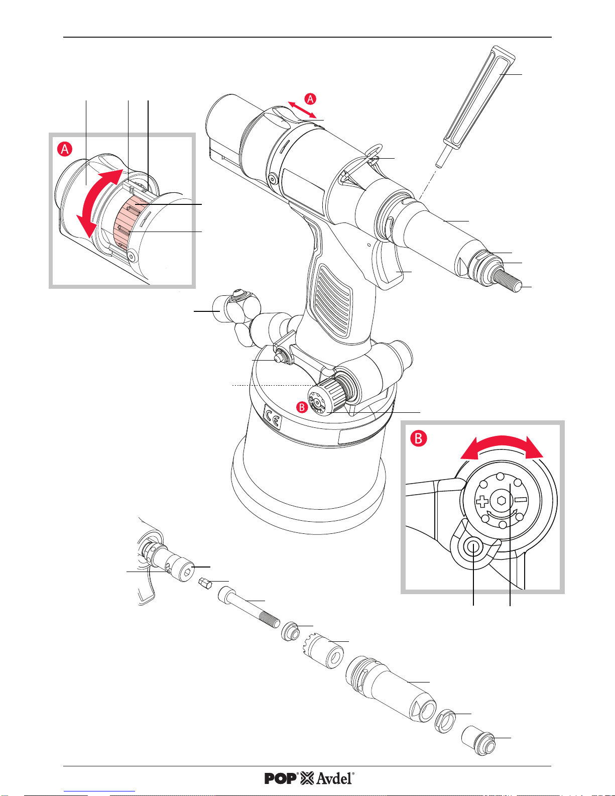
ref g. 1 & 2 Re-order
Spare part numbers Qty
1 Mandrel
M4 07555-09004 1
M5 07555-09005 1
M6 07555-09006 1
M8 07555-09008 1
2 Nose Tip
M4 07555-00904 1
M5 07555-00905 1
M6 07555-00906 1
M8 07555-00908 1
3 Lock Nut - 07555-00901 1
4 Nose Casing - 74202-02021 1
5 Chuck Nut - 74202-02022 1
6 Reducing Sleeve
M4 07555-09104 1
M5 07555-09105 1
M6 07555-09106 1
M8 07555-09108 1
7 Drive Shaft
M4 07555-01004 1
M5 07555-01005 1
M6 07555-01006 1
M8 07555-01008 1
8 Mandrel Adaptor - 74202-02023 1
9 Nose Rod - 74202-02039 10 Suspension Ring - 74202-02012 1
11 Stroke Slider - 74202-02092 1
12 Stroke Indication Markings - - 13 Stroke Locking Pin - 74202-02095 1
14 Stroke Setter - 74202-02010 1
15 Stroke Setter Recess - - 16 Air Inlet Assembly - 74202-02103 1
17 Manual Reverse Trigger - 74202-02030 1
18 Regulator Lock - 74202-02038 1
19 Pressure Regulator - 74202-02037 1
20 Trigger - 74202-02020 1
21 Pin Punch - 07900-00624 1
Complete nose assembly
M4 07555-09884
M5 07555-09885
M6 07555-09886
M8 07555-09888
* All sizes are supplied with Lock Nut (3) 07555-00901.
For additional sizes please visit www.StanleyEngineeredFastening.com
9
ENGLISH
Page 10

3. Tool Setup
IMPORTANT - READ THE SAFETY RULES ON PAGE 6 & 7 CAREFULLY BEFORE PUTTING INTO SERVICE.
Before Use
• Select relevant size nose equipment and install.
• Connect the placing tool to the air supply. Test pull and return cycles by depressing and releasing the
trigger 20.
• Set the tool for desired stroke/pressure.
CAUTION - correct supply pressure is important for proper function of the installation tool. Personal injury or
damage to equipment may occur without correct pressures. The supply pressure must not exceed that listed in the
placing tool speci cation.
4. Operating Instructions
IMPORTANT - READ THE SAFETY RULES ON PAGE 6 & 7 CAREFULLY BEFORE PUTTING INTO SERVICE.
IMPORTANT - THE AIR SUPPLY MUST BE TURNED OFF OR DISCONNECTED BEFORE FITTING OR
REMOVING THE NOSE ASSEMBLY.
4.1 Nose Equipment (see Fig.2).
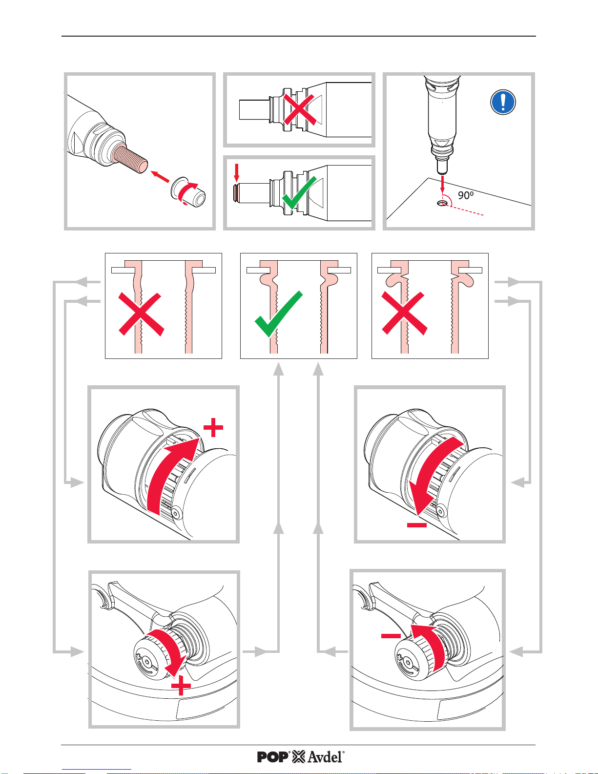
Fitting Instructions
Item numbers in bold refer to nose assembly components in g 1.
• Air supply must be disconnected.
• If still tted, remove the Nose Casing 4 and the Chuck Nut 5,while pulling back the spring loaded Nose
Rod 9. •
• Insert Drive Shaft 7 into Mandrel Adaptor 8.
• Fit Mandrel 1 onto Drive Shaft 7.
• Insert Reducing Sleeve 6 (if speci ed) into the Chuck Nut 5.
• Screw the Chuck Nut 5 onto the Mandrel Adaptor 8 while pulling back the spring loaded Nose Rod 9.
Tighten the Chuck Nut 5 clockwise.
• While holding the Tool, screw on the Nose Casing 4 and Nose Tip 2 with the nose tip Lock Nut 3.
• The reverse operation is carried out for equipment removal.
With the tool still disconnected from the air supply, screw a Blind Rivet Nut onto the Mandrel manually.
• Position Nose Tip 2 on the Nose Casing 4 and lock it with Lock Nut 3 so that the Mandrel 1 protrudes
slightly beyond the insert.
• Lock the Lock Nut 3 by turning clockwise with a spanner*. Remove the Blind Rivet Nut from
Mandrel.
*Refer to items included in the Maintenance Kit 07900-09301 page 13.
10
ENGLISH
Page 11
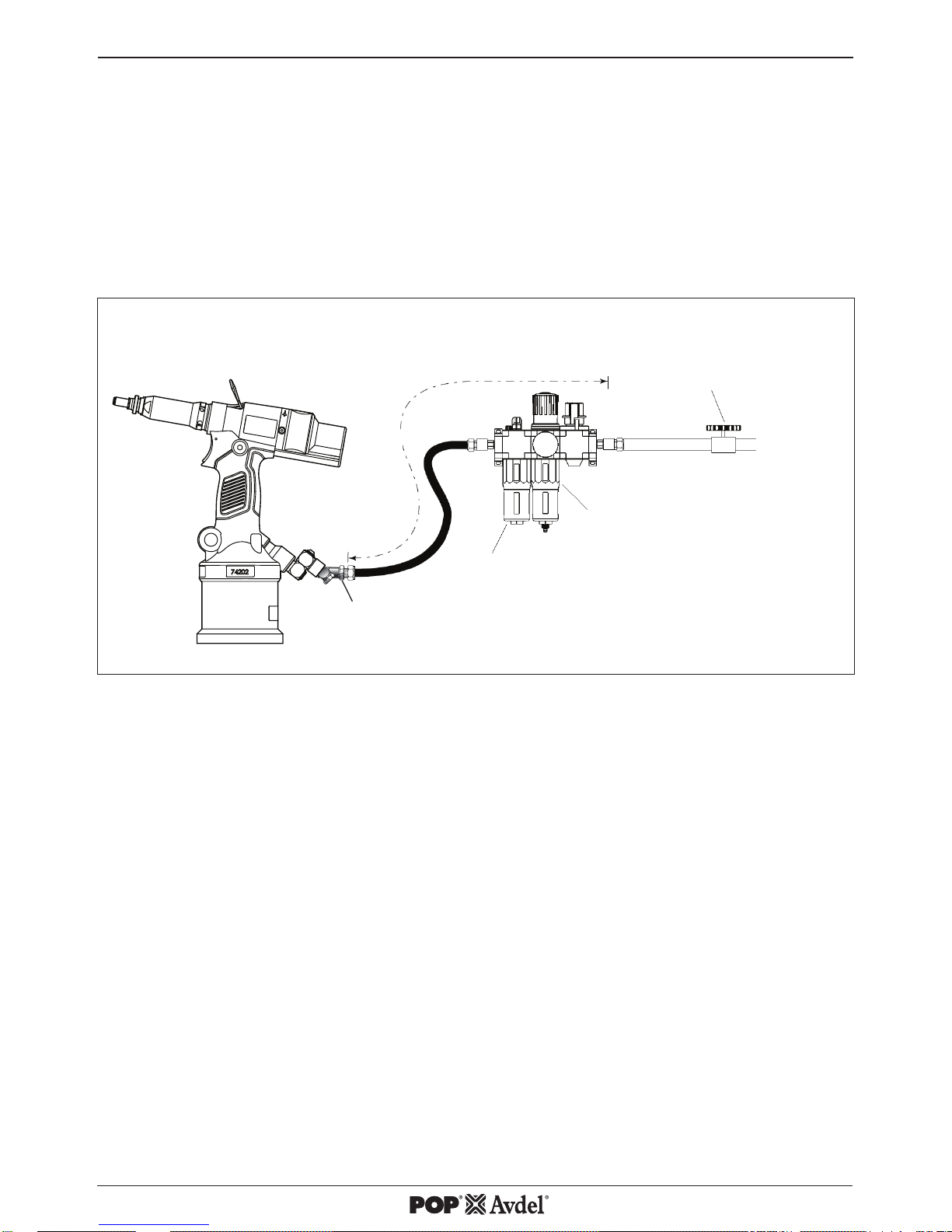
4.2 Air Supply
• All tools are operated with compressed air at an minimum pressure of 5.0 bar.
• Pressure regulators and automatic oiling/ ltering systems to be used on the main air supply within 3
metres of the tool (see g. 4).
• Air supply hoses will have a minimum working e ective pressure rating of 150% of the maximum pressure
produced in the system or 10 bar, whichever is the highest.
• Air hoses must be oil resistant, have an abrasion resistant exterior and be armoured where operating
conditions may result in hoses being damaged.
• All air hoses MUST have a minimum bore diameter of 6.4 millimetres.
LUBRICATOR
PRESSURE REGULATOR AND
FILTER DRAIN DAILY
STOP COCK
USED DURING MAINTENANCE
OF FILTER/REGULATOR OR
LUBRICATION UNITS
MAIN SUPPLY
3 METRES MAXIMUM
If above system is not available you can use the following alternative:
• Before use or when rst putting the tool into service, pour a few drops of clean, light lubricating oil into
the air inlet of the tool if no lubricator is tted on air supply. If the tool is in continuous use, the air hose
should be disconnected from the main air supply and the tool lubricated every two to three hours.
• Check for air leaks. If damaged, hoses and couplings must be replaced by new items.
• If there is no lter on the pressure regulator, bleed the air line to clear it of accumulated dirt or water
before connecting air hose to the tool.
4.3 Setting Instructions
• The stroke adjustment feature is mainly used for smaller insert sizes M3-M4.
• If you are setting the tool for optimum stroke the Stroke Setter should be wound in to minimum stroke
(3mm) and the Pressure Regulator 19 be wound in to maximum setting.
• If you are setting the tool for optimum pressure the Stroke Setter should be wound out to maximum
stroke (7mm) and the Pressure Regulator 19 be wound out to minimum setting.
When dealing with di erent grip thicknesses, it is always recommended that the tool is set for optimum
pressure rather than optimum stroke. Use the maximum grip condition to set optimum pressure.
Fig. 4
1/4" GAS
CONNECTION
11
ENGLISH
Page 12

4.3.1. Stroke Adjustment (see Fig. 1A & 3).
To use this tool in stroke set operation, screw the Pressure Regulator 19 fully in to achieve full pressure then
adjust Stroke Setter to the desired stroke length:
• Open Stroke Slider 11.
• The Stroke Locking Pin 13 will be released.
• Directional arrows indicate stoke direction.
• Increase the stroke from the minimum until optimum deformation is obtained.
• The scale gives an indication of the current stroke length.
• Increments 12 shown are 3, 5 and 7mm on one side and 4 and 6mm on the opposite.
• Line the rear of the Stroke Setter 14 up with these marks to achieve desired stroke length.
• Each Recess 15 on the Stroke Setter 14 is equal to +- 0.1mm of stroke.
• Close the Stroke Slider 11 before using in the application environment.
• The Stroke Lock will activate when the Stroke Slider 11 is closed when the tool is in the upright position
• The tool is now ready to operate.
4.3.2. Pressure Adjustment (see Fig. 1B & 3).
To use this tool in pressure set operation, wind the Stroke Setter 14 to 7mm, then screw the Pressure
Regulator 19 fully out to achieve minimum pressure then adjust to the desired pressure:
• Initially the Blind Rivet Nut will not deform and the tool will spin o .
• Screw in the Pressure Regulator 19 by 1 groove on the regulator body and test.
• Repeat the operation with the Pressure Regulator 19 until optimum deformation is obtained.
• 1 notch on the Pressure Regulator 19 is equivalent to approximately 20N of pulling force.
• After a successful Blind Rivet Nut deformation, check the Blind Rivet Nut and increase the force if
necessary.
• Increase by 1-2 notches extra to allow for variation in the Blind Rivet Nuts.
• The tool is now ready to operate.
5. Operating Procedure
Installing a Blind Rivet Nut (see Fig. 3).
To install a Blind Rivet Nut.
• Check that the correct Blind Rivet Nut has been selected.
• Push Blind Rivet Nut into the application.
• Check Nose Assembly is at right angle (90°) to the work.
• Push onto the Blind Rivet Nut with the tool to spin on.
• Once fully and correctly inserted, depress tool Trigger 20 switch to start installation cycle.
• Hold the Trigger 20 until the Blind Rivet Nut is completely set and the tool has disengaged completely.
In the event a Blind Rivet Nut becomes jammed in an application press the Manual Reverse Trigger 17 to
reverse the Mandrel 1 and spin o the Blind Rivet Nut. Alternately disconnect from the air supply and use the
4mm Pin Punch 21 supplied in the Maintenance Kit to wind o the Mandrel through the Nose Casing 4 shown
in the gure 1.
CAUTION - do not attempt to force the installation of an insert as this will cause damage to the tool and/or
application.
12
ENGLISH
Page 13

6. Servicing the Tool
Regular servicing must be carried out by trained personnel and a comprehensive inspection performed
annually or every 500,000 cycles, whichever is sooner.
Cleaning and Maintenance
DISCONNECT AIR SUPPLY
Nose assemblies should be serviced at weekly intervals or every 5,000 cycles
CAUTION - Blow dirt and dust out of the main housing with dry air as often as dirt is seen collecting in and
around the air vents where the Pneumatic Cylinder connects to the plastic Handle Assembly. Wear approved eye
protection and approved dust mask when performing this procedure.
CAUTION - Never use solvents or other harsh chemicals for cleaning the non-metallic parts of the tool. These
chemicals may weaken the materials used in these parts.
• Disconnect the air supply
• Remove the complete nose assembly using the reverse procedure to the Fitting Instructions page 10(4.1).
• Any worn or damaged part must be replaced by a new part.
• Particularly check wear on Mandrel.
• Assemble according to tting instructions.
6.1 Daily Servicing
• Check for air leaks. If damaged, hoses and couplings must be replaced by new items.
• Check that the Nose Assembly is correct and tted properly.
• Check if the stroke of the tool is adequate to place selected Blind Rivet Nut. See Stroke Adjustment page
12 (4.3.1.).
• Inspect the Mandrel 1 in the nose assembly for wear or damage. If any, replace.
6.2 Weekly Servicing
• Check for oil leaks and air leaks on air supply hose and ttings and tool.
• With the tool laid horizontally, open “Oil Plug” and check oil level, if low re-prime, refer to “Service manual,
Section 6”.
For full servicing, troubleshooting and maintenance instructions please refer to Service Manual 07900-09302.
Maintenance Kit 07900-09301
Part Number Description Qty
07900-00624 4mm Pin Punch 1
07900-00632 17mm/19mm Spanner 1
07900-00225 5mm Hexagonal Wrench 1
13
ENGLISH
Page 14

7. Declaration of Conformity
We, Avdel UK Limited, Stanley House, Works Road, Letchworth Garden City, Hertfordshire,
SG6 1JY UNITED KINGDOM, declare under our sole responsibility that the product:
Description ProSert® XTN20 Hydro-Pneumatic Blind Rivet Nut Tool
Brand/Model POP-Avdel 74202
Serial No.
to which this declaration relates is in conformity with the following standards:
ISO 12100:2010 EN ISO 28927-5:2009
EN ISO 11202:2010 EN ISO 3744:2010
EN ISO 4413:2010 EN ISO 11148-1:2011
EN ISO 4414:2010 EN 28662-1: 1993
Technical documentation is compiled in accordance with Annex 1, section 1.7.4.1,
in accordance with the following Directive:
2006/42/EC The Machinery Directive
UK Statutory Instruments 2008 No 1597 - The Supply of Machinery (Safety) Regulations refers.
A. K. Seewraj
Technology Manager – EU Blind Fastening
Avdel UK Limited, Stanley House, Works Road, Letchworth Garden City,
Hertfordshire, SG6 1JY UNITED KINGDOM
Place of issue: Letchworth Garden City
Date of issue: 01-04-2015
This machinery is in conformity with
Machinery Directive 2006/42/EC
Original Instruction
14
ENGLISH
Page 15

8. Protect your Investment!
POP®Avdel® BLIND RIVET NUT TOOL WARRANTY
STANLEY Engineered Fastening warrants that all power tools have been carefully manufactured and that they
will be free from defect in material and workmanship under normal use and service for a period of one (1)
year.
This warranty applies to the rst time purchaser of the tool for original use only.
Exclusions:
Normal wear and tear.
Periodic maintenance, repair and replacement parts due to normal wear and tear are excluded from coverage.
Abuse & Misuse.
Defect or damage that results from improper operation, storage, misuse or abuse, accident or neglect, such as
physical damage are excluded from coverage.
Unauthorized Service or Modi cation.
Defects or damages resulting from service, testing adjustment, installation, maintenance, alteration or
modi cation in any way by anyone other than STANLEY Engineered Fastening, or its authorized service
centres, are excluded from coverage.
All other warranties, whether expressed or implied, including any warranties of merchantability or tness for
purpose are hereby excluded.
Should this tool fail to meet the warranty, promptly return the tool to our factory authorized service centre
location nearest you. For a list of POP®Avdel®Authorized Service Centres in the US or Canada, contact us at our
toll free number (877)364 2781.
Outside the US and Canada, visit our website www.StanleyEngineeredFastening.com to find your nearest
STANLEY Engineered Fastening location.
STANLEY Engineered Fastening will then replace, free of charge, any part or parts found by us to be defective
due to faulty material or workmanship, and return the tool prepaid. This represents our sole obligation under this
warranty. In no event shall STANLEY Engineered Fastening be liable for any consequential or special damages
arising out of the purchase or use of this tool.
Register Your Blind Rivet Nut Tool online.
To register your warranty online, visit us
http://www.stanleyengineeredfastening.com/popavdel-powertools/warranty-card
Thank you for choosing an STANLEY Engineered Fastening’s POP®Avdel® Brand tool.
15
ENGLISH
Page 16

Page 17

目次
ページ
1. 安全の定義 6
2. 仕様 8
2.1 ツール仕様 8
2.2 同梱内容 8
2.3 部品リスト 9
3. ツールセットアップ 10
4. 操作方法 10
4.1 ノーズエクイップメント 10
4.2 エア供給 11
4.3 設定方法 11
5. 操作手順 12
6. ツールメンテナンス 13
6.1 日常点検 13
6.2 毎週点検 13
7. 適合宣言 14
8. 製品保証 15
© 2015 Stanley Black & Decker, Inc.
無断転載禁止
本説明書で示された情報は、STANLEY Engineered Fastening からの事前の明示および書面による許
可なしに、いかなる手段 (電子的または機械的) によっても複製かつまたはいかなる方法による公開
も許可しません。示された情報は、本製品の紹介時点で知られたデータに基づいています。STANLEY
Engineered Fastening は継続的な製品の改善により、製品の仕様は変更の対象となる場合がありま
す。示された情報は、STANLEY Engineered Fastening によって出荷された時点で製品に適用されま
す。そのため、STANLEY Engineered Fastening は製品のオリジナル仕様からかけ離れていることに起
因する損傷については責任を持つことはできません。
利用可能な情報は最大限の注意を払っていますが、STANLEY Engineered Fasteningは情報のいか
なる誤りおよびそれが原因で生じる結果に関しても責任を受け入れません。STANLEY Engineered
Fastening は、第三者によって行われた行為によって引き起こされた損傷についての責任を受け入れ
ません。STANLEY Engineered Fastening によって使用される作業名、商品名、登録商標 などは、登
録商標保護法に従い制限されています。
はじめに
日本語
5
Page 18

この取扱説明書は、以下の安全上のルールに注意を払いながら セットアップまたは操作をする人 に
読んで頂く必要があります。
1. 安全の定義
下記の定義は各シグナルの言葉に対する重大さのレベルを示しています。マニュアルを良く読み、こ
れらの表示に注意を払ってください。
危険:回避しないとただちに死亡や重大なケガにつながる危険な状態。
v 警告:回避しないと死亡や重大なケガにつながる恐れのある危険な状態。
注意:回避しないとケガにつながる恐れのある危険な状態。
注意:回避しないと設備などの損傷につながる恐れのある危険な状態。
本製品の操作やメンテナンスを正しく行わないと、重大なケガや設備の損傷などにつながる恐れがあ
ります。警告や操作説明手順は使用する前にすべてよく読んでください。ツールを使用する際は、ケ
ガのリスクを軽減するため、必ず基本的な安全の注意事項に従ってください。
説明書は必ず保管してください。
警告:
1. STANLEY Engineered Fastening社のブラインドリベットリベットナットの締結目的以外には使用し
ないでください。
2. 部品、ファスナー、付属品は、メーカー推奨のものを使用してください。
3. いかなる場合も本製品を改造しないこと。改造による全責任はお客様が負うものとし、製品の品質
保証は無効となります。
4. 使用前に可動部の接続や外れ、部品の損傷、そのほかツールの操作に影響するような状態がないか
確認してください。損傷していた場合は、使用前にツールを修理に出してください。使用前に調
整キーやレンチを取り外さないでください。
5. ツールや設備は、常に安全な作業状態に置き、トレーニングを受けた人員が定期的に損傷の有無や
機能を確認してください。ツールや設備の分解はトレーニングを受けた人員のみが実施し、メン
テナンス手順書を事前に参照したうえで行ってください。
6. 供給エアは 7 bar (100 PSI) を超えないようにしてください。
7. オペレータ本人及び作業エリアにいる他の人員は、側面の保護の付いた承認済みの安全メガネ
ANSI Z87.1 CAN/CSA Z94.3 をかける必要があります。操作中は常に安全メガネおよび防音保護具
を身 に着けてください。
日本語
6
Page 19

8. 衣服をきちんと着用してください。ゆったりした服装や貴金属類は身に着けないでください。
髪、衣服、手袋を可動部分から離してください。ゆったりした服装、貴金属類や長い髪は可動部
に引き込まれる可能性があります。
9. 人に向けての本機の操作は行わないでください。
10. ノーズハウジングを外した状態で操作しないでください。
11. ツールを操作する前に、足元をしっかり固めるか安定した位置を確保してください。
12. 使用前に、エア配管に損傷がない事を確認し、接続部がきちんと接続されているか確認してくだ
さい。ホースの上に重いものを落とさないこと。先のとがったものが当たるとホース内部が損傷
する恐れがあります。
13. ホースでツールを持ち上げないでください。必ずツールのハンドル部を使用して ください。
14. 通気穴はブロックされたりカバーされたりしないようにしてください。
15. 保守作業の前、ノーズアセンブリの調整、取付け、取外しをする前には本機からエアホースを外
してください。
16. ツールのハンドルの部分は乾いたきれいな状態を保ち、油やグリスの付着がないようにしてくだ
さい。
17. ツールを持ち運ぶ場合は、トリガから手を離して不用意な作動を避けてください。
18. ツールの作動中はツールから離れないでください。ツールを使用していないときはエアホースを
取り外してください。
19. ツールのオペレータの手前方には適切なクリアランスが必要です。
20. ツールを落としたり、ハンマーとして使用したりしないこと。
21. ツールが誤動作する原因になるため、本機の油圧システムに汚れ、異物が付かないようにしてく
ださい。
STANLEY Engineered Fastening のポリシー
は、絶え間ない製品の開発と改善
当社は予告なしに製品の仕様を変更する
権利を有します。
日本語
7
Page 20

* の付いた項目は、マンドレルアダプタキット (アクセサリのマニュアル (07900-01073) の中にある 74202-02200)
が必要な場合があります。完全な ProSert® XTN20 (74202) 機は、ベースツール (部品番号 74202-02000) および
挿入用に適合するノーズアセンブリから構成されます。
2. 仕様
いかなる場合も、メンテナンスや修理でノーズエクイップメントの部品の変更はしないこと。
ProSert® XTN20 油空圧ブラインドリベットナット ツールは、荷重またはストローク調整により
STANLEY Engineered Fastening のブラインドリベットナットを締結するために設計されています
ProSert® XTN20 ツールは、関連するノーズエクイップメントと結合したとき、M3 から M10 までのブ
ラインドリベットナットを締結するために使用されます。英本国法定の標準に従うノーズエクイップ
メントは、UNC および UNF インチサイズのブラインドリベットナットの締結にも使用できます。
安全のための注意事項には必ず従ってください。
2.1. ツール仕様
2.2. 同梱の内容:
• XTN20 ブラインド リベット ナット ツール 1 式
• M4, M5, M6, M8 エクイップメント & マンドレル 1 セット
• 取扱説明書 1 冊
• 保守用品 1 キット
引力:
エア圧 5.0 bar 時の引力
17.65 kN 3968 lbf
エア供給圧 最小/最大 5~7 bar
72.5~101.5 lbf/in
2
オイル圧 最大 230 bar 3336 lbf/in
2
ストローク: 最小/最大 3~7 mm
0.118~0.275 in
重量: 含 ノーズエクイップメント 1.59 kg 3.50 lb
ノイズレベル: K=3dB(A) <75 dB(A) <75 dB(A)
振動レベル: K=0.1 m/s² <2.5 m/s
2
<8 ft/s
2
モータ速度: 正転/反転 2000rpm 2000rpm
その他の特長:
荷重管理の操作モード 搭載
ストローク管理の操作モード
搭載
ナットの自動装着/自動離脱 搭載
工具不要のマンドレル脱着 搭載
手動反転ボタン 搭載
油圧リップシール & O-リング 搭載
材質 -
アルミ二ウム スチール ステンレス
Avdel® シリーズ:
Eurosert® - M3~M10 M4~M5
Thin Sheet Nutsert® M3~M10 M3~M10 M3~M10
DK/DL M4~M10 M4~M10 -
Euro Hexsert®/Hexsert®
- M3~M8 M6
High Strength Hexsert®
- M6~M8 -
Squaresert® - M5~M8 -
POP Nut®シリーズ:
Standard Nut* M3~M10 M3~M8 M4~M6
Knurled Nut* - M4~M5 Closed End Nut* M4~M8 M3~M8 M4,M6
Hexagonal Nut* M4~M8 M4~M8 M4,M6
Tetra Nut* - M4~M8 HB Bolt* - M6 Pipe Nut* - M5~M8 -
日本語
8
Page 21

2.3.主要部品表
参考 図 1 および図 2 再注文
スペア部品番号 員数
1 マンドレル
M4 07555-09004 1
M5 07555-09005 1
M6 07555-09006 1
M8 07555-09008 1
2 ノーズチップ
M4 07555-00904 1
M5 07555-00905 1
M6 07555-00906 1
M8 07555-00908 1
3 ロックナット - 07555-00901 1
4 ノーズケース - 74202-02021 1
5 チャックナット - 74202-02022 1
6 レデューシングスリーブ
M4 07555-09104 1
M5 07555-09105 1
M6 07555-09106 1
M8 07555-09108 1
7 ドライブシャフト
M4 07555-01004 1
M5 07555-01005 1
M6 07555-01006 1
M8 07555-01008 1
8 マンドレルアダプタ - 74202-02023 1
9 ノーズロッド - 74202-02039 10 サスペンションリング - 74202-02012 1
11 ストロークスライダー - 74202-02092 1
12 ストローク表示マーク - - 13 ストロークロックピン - 74202-02095 1
14 ストロークセッター - 74202-02010 1
15 ストロークセッター溝 - - 16 吸気口アセンブリ - 74202-02103 1
17 手動逆転ボタン - 74202-02030 1
18 レギュレータロック - 74202-02038 1
19 圧力レギュレータ - 74202-02037 1
20 トリガ - 74202-02020 1
21 パンチピン - 07900-00624 1
ノーズアセンブリ フルセット
M4 07555-09884
M5 07555-09885
M6 07555-09886
M8 07555-09888
* 全サイズがロックナット (3) 07555-00901 と共に供給されます。
追加のサイズについては www.StanleyEngineeredFastening.com を見てください。
日本語
9
Page 22

3. ツールセットアップ
重要 -作業を開始する前に必ず安全のルール(P.6及びP7)をよく読んでください。
• 正しいサイズのノーズエクイップメントを選択し取付けてください。
• ツールに供給エアを接続してください。トリガ 20 を引いたり離したりして引込みと戻りのサイ
クルをテストしてください。
• ツールを希望するストローク/荷重に設定してください。
注意 - 適切な供給エア圧はツールの正しい動作機能に重要です。正しいエア圧が供給されない
と、人 に傷害を与えたり設備に損傷を与えたりする恐れがあります。供給エア圧はツール仕様範囲を
超えてはいけません。
4. 操作方法
重要 - 作業を開始する前に必ず安全のルール(P.6及びP7)をよく読んでください。
重要 - ノーズアセンブリ脱着の前に、エアの供給を止めてください。
4.1 ノーズエクイップメント装置 (図.2 参照) 取付けの説明
取付けの説明
図 1 で太字の項目番号はノーズアセンブリの部品を参照しています。
• エア供給は止めておく必要があります。
• まだ取り付けられている場合は、ノーズロッド 9 に付けられたスプリングを引き抜きながら、ノ
ーズケース 4 とチャックナット 5 を取り外します。•
• ドライブシャフト 7 をマンドレルアダプタ 8 に挿入します。
• マンドレル 1 をドライブシャフト 7 に取り付けます。
• レデューシングスリーブ 6 (必要に応じて) を チャックナット 5 に挿入します。
• ノーズロッド 9 に付けられたスプリングを引き抜きながら、マンドレルアダプタ 8 にチャック
ナット 5 をねじ込みます。チャックナット 5 を時計回りに締め付けます。
• ツールを保持しながら、ノーズケース 4 とノーズチップ 2 をノーズチップロックナット 3 でね
じ止めします。
• ノーズエクイップメントの取外しは、上記と逆の手順で行ってください。
ツールがまだ供給エアから切り離されている状態で、ブラインドリベットナットをマンドレルに手で
装着します。
• ノーズチップ 2 をノーズケース 4 に位置決めし、マンドレル 1 がインサートよりわずかに突き
出すようにロックナット 3 で固定します。
• ロックナット 3 をスパナ* で時計回りに回して固定します。マンドレルをブラインドリベット
ナットから取外します。
* 保守キット 07900-09301の 13 ページにある項目を参照してください。
日本語
10
Page 23

4.2 エア供給
• 本機は最小圧力 5.0 bar の供給エアで動作します。
• 圧力レギュレータと自動オイル/フィルタシステムを本機から 3m 以内のメインのエア供給で使用
します。 (図. 4 を参照)
• エア供給ホースには、システムで作られる最大圧力の 150% または 10 bar のどちらか高い方の
最小作業効果的圧力レートがあります。
• エアホースはオイル抵抗があり、外面には摩耗抵抗があり、操作条件がホースの損傷を招く場合
がある場所では外側を守られている必要があります。
• すべてのエアホースは必ず 6.4 mm の最小内径を持っている必要があります。
ル
ブリケータ
ー
レギュレータとエアフィルタ
(毎日 排出のこと)
停止コック
(フィルタ/レギュレータまたは
潤滑装置の保守の際に使用)
メイン供給
エア
最大 3M
図4の環境が利用できない場合は、代替として以下の方法を実施してください。
• 使用前またはツールを使い始めるにあたって、ルブリケーターがエア供給ラインに付けられてい
ない場合、新品の潤滑油を数滴本機のエア吸気口に注いでください。ツールを連続使用する場合
は、エアホースをメインの供給エアから切り離し、本機を2、3 時間毎に給油します。
• エア洩れがないか確認します。損傷がある場合、ホースとカップリングは新しいものと交換して
ください。
• レギュレータにフィルタがない場合は、エアホースをツールに接続する前に共有エアを止めて
溜まっている汚れまたは水を取り除きます。
4.3 設定方法
• ストローク調整機能は主に M3~M4 の小さいサイズのブラインドリベットナットに使用します。
• ストロークセッター14を使用してツールのストロークを設定する場合は、ストロークセッターを
最少ストローク(3mm)まで回し、プレッシャーレギュレーター19を最大設定値まで回す。
• プレッシャーレギュレーター19を使用して設定する場合は、ストロークセッターは最大ストロー
ク (7mm) まで回し、プレッシャーレギュレーター19 は最小の設定まで回します。
異なる母材板厚に対応するときは、ツールをストローク管理よりも荷重管理に設定することを推奨し
ます。最大母材板厚の条件を使って荷重を設定します。
図 4
1/4"
管用ネジ
接続
日本語
11
Page 24

4.3.1.ストローク調整 (図 1A、3 を参照)
本機をストローク設定で使用するためには、圧力レギュレータ 19 を完全に締め最大圧力にし、その
後ストロークセッターを調整して任意のストロークに調整します。
• ストロークスライダ 11 を開きます。
• ストロークロックピン 13 が解放します。
• 矢印はストロークの方向を示します。
• ストロークを最小から最適な座屈が得られるまで調整します。
• スケールは現在のストローク長を示します。
• ストローク表示マーク12 は片側 3、5、7mm、反対側 4、6mm です。
• ストロークセッター 14 の後ろをこれらのマークに合わせて望みのストローク長さを得ます。
• ストロークセッター 14 のストロークセッター溝 15 はストロークの +- 0.1mm です。
• 使用する前に、ストロークスライダ 11 を閉めます。
• ストロークロックピン13は、ストロークスライダ11が閉じていてツールが直立の状態で作動します。
• ストローク調整が完了しました。
4.3.2.圧力調整 (図 1B、3 を参照)
本機を圧力設定の操作で使用するには、ストロークセッター 14 を 7mm まで巻き、その後圧力レギ
ュレータ 19 を完全にねじ止めして最小圧力を得て、それから希望の圧力に調整します。
• 最初 トリガを引くとブラインドリベットナットは座屈せずツールから離脱します。
• 圧力レギュレータ 19 を1 ノッチだけ緩めテストします。
• 最適な座屈が得られるまで圧力レギュレータ 19 でこの操作を繰り返します。
• 圧力レギュレータ 19 の 1 ノッチは引込み力のおよそ 20N に相当します。
• ブラインドリベットナットの座屈が最適になった後は、ブラインドリベットナットを確認し、必
要に応じて荷重を大きくします。
• 1~2 ノッチ分さらに増やすとブラインドリベットナットの座屈が安定します。
• 荷重調整が完了しました。
5. 操作手順
ブラインドリベットナットの締結 (図 3 を参照)
ブラインドリベットナットを締結には、
• 適切なブラインドリベットナットであるかを確認します。
• ブラインドリベットナットを母材に挿入します。
• ノーズアセンブリをワークに対して直角 (90°) にします。
• ブラインドリベットナットをマンドレルに押し付け 装着します。
• 十分かつ正確に挿入されたら、本機のトリガ 20 のスイッチを押し取付けのサイクルを開始しま
す。
• ブラインドリベットナットが完全にセットされ、ツールが分離するまでトリガ 20 を保持 しま
す。
ブラインドリベットナットがマンドレル1に噛み込んだ場合には、手動逆転トリガ 17 を押し、マンド
レル 1 を逆転させブラインドリベットナットを取り除きます。あるいは、供給エアを切り離し保守キ
ットの 4mm パンチピン 21 を使ってマンドレル1を図 1 のノーズケース の穴から回してブラインド
リベットナットから外します。
注意 - ツールやマンドレルが損傷する恐れがあるため、ブラインドリベットナットを無理に装
着しないこと。
日本語
12
Page 25

6. ツールメンテナンス
トレーニングを受けた人によって定期的な保守を行い総合的な検査を年に 1 回または 50万 サイクル
毎の どちらか早い方の時点で行う必要があります。
清掃とメンテナンス
供給エアの切り離し
ノーズアセンブリは週に 1 回または 5,000 サイクル毎に保守します。
注意 - ケース本体や、チャンバーをプラスチック製ハンドルに接続するエアベント付近に汚れ
やほこりが目立つ場合は、エアで吹き飛ばすこと。
その際、必ず保護メガネや防塵マスクを着用すること。
注意 - 非金属部の材質が劣化する恐れがあるため、ツールの非金属部の清掃に溶剤やその他の
化学薬品を使用しないこと。
• 供給エアを切り離します。
• ノーズアセンブリ取付けの説明のページ 10(4.1) と逆の手順で取り外します。
• 摩耗や損傷を受けた部品は新しい部品に交換する必要があります。
• マンドレルの摩耗は必ず確認してください。
• 取り付け手順に従って組み立てます。
6.1 日常点検
• エア洩れがないか確認します。損傷がある場合、ホースとカップリングは新しいものと交換して
ください。
• ノーズアセンブリが正しく適切に取り付けられていることを確認します。
• ツールのストロークが選択したブラインドリベットナットを締結するのに適切かどうかを確認し
ます。ストローク調整のページ 12 (4.3.1.) を参照してください。
• ノーズアッセンブリ―のマンドレル1の摩耗や損傷を点検する。摩耗、損傷している場合は、交換
してください。
6.2 毎週点検
• エア供給ホース、取付部品、本体にオイル、エア洩れがないか確認します。
• ツールを水平に置いた状態で、「オイルプラグ」を開いてオイルレベルを確認し、低い場合は「
サービスマニュアルのセクション 6」を参照してオイル補充します。
メンテナンス全般、トラブルシューティング、メンテナンスの説明については、サービスマニュアル
07900-09302 を参照してください。
保守キット 07900-09301
部品番号 品名 員数
07900-00624 4mm ピンパンチ 1
07900-00632 17mm/19mm スパナ 1
07900-00225 5mm 六角レンチ 1
日本語
13
Page 26

7.適合宣言
当社Avdel UK Limited, Stanley House, Works Road, Letchworth Garden City, Hertfordshire,
SG6 1JY UNITED KINGDOM は以下に明記する製品について責任を負うと宣言します。
対象 ProSert® XTN20 油空圧式ブラインドリベットナッ
トツール
ブランド/モデル POP-Avdel 74202
シリアル番号
本製品は以下の基準に適合しています。
ISO 12100:2010 EN ISO 28927-5:2009
EN ISO 11202:2010 EN ISO 3744:2010
EN ISO 4413:2010 EN ISO 11148-1:2011
EN ISO 4414:2010 EN 28662-1:1993
技術データは以下の指令に基づき、付録1、条項1.7.4.1に編纂されています。
2006/42/EC The Machinery Directive
UK Statuory Instruments 2008 No 1597 – The Supply of Machinery (Safety) Regulations 参照
A.K.Seewraj
Technology Manager – EU Blind Fastening
Avdel UK Limited, Stanely House, Works Road, Letchworth Garden City,
Hertfordshire, SG6 1JY UNITED KINGDOM
発行場所:Letchworth Garden City
発行年月日:2015 年 4 月 1 日
本機械は機械指令 2006/42/EC に
。準拠しています
はじめに
日本語
14
Page 27

8.製品保証
POP®Avdel® ブラインドリベットナット ツール保証
STANLEY Engineered Fastening は、全電動ツールが注意深く製造されていること、材料および製造品
は 1 年間の通常の使用および保守の下で欠陥が発生しないことを保証します。
本保証は、オリジナルな使用のみを目的としたツールの最初のご購入に対して適用します。
免責条項:
通常の摩耗および亀裂
定期的なメンテナンス、修理および通常の摩耗、亀裂による部品の交換は適用対象から除外されます。
不正使用 & 誤使用
物理的な損傷など、不適切な操作、保存、誤使用または不正使用、事故または不注意による欠陥また
損傷は適用対象から除外されます。
未承認の保守または改造
STANLEY Engineered Fastening ならびに許可を受けたサービスセンター以外の者による点検、調整、
装着、メンテナンス、変更や改造に起因する不具合や損傷はいかなる場合も、保証されません。
その他すべての保証は、表記されたものまたは暗示されたものであっても、市場性または目的適合性
のいかなる保証も含めてここに除外されます。
ツールが保証条件に合致しない場合は、速やかにお近くの弊社サービスセンターまで製品を返却して
ください。米国およびカナダ国内のPOP Avdelサービスセンター一覧については、8773642781(電話料
無料)にお電話ください。
米国およびカナダ以外については、下記の弊社ホームページでお近くのサービスセンターをご確認く
ださい。www.StanleyEngineeredFastening.com
部品及び製品の不具合による不良ついては、弊社で部品交換を行い、お客様に返送いたします。保証
義務に基づき、部品交換及び送料はすべて弊社で負担いたします。ただし、製品の購入や使用による
特殊な損傷などについては責任を負いません
お使いのブラインドリベットナットツールをオンライン登録してく
ださい
オンラインでの保証登録ができます。
http://www.stanleyengineeredfastening.com/popavdel-powertools/warranty-card
この度は、弊社製品をお買い上げいただきありがとうございました。
日本語
15
Page 28

Page 29

目录
页码
1. 安全说明 6
2. 技术参数 8
2.1 拉帽枪技术参数 8
2.2 拉帽枪组件 8
2.3 主要部件列表 9
3. 拉帽枪安装 10
4. 操作说明 10
4.1 枪嘴装置 10
4.2 气源 11
4.3 调节说明 11
5. 操作程序 12
6. 拉帽枪维护 13
6.1 日常维护 13
6.2 每周维护 13
7. 一致性声明 14
8. 保护你的投资。保修登记 15
© 2015 Stanley Black & Decker, Inc.
版权所有。
未经史丹利工程紧固系统公司的事先明确书面允许,禁止以任何方式以及通过任何电子或机械手段复制
和/或公开所提供的信息。本手册中所提供的信息基于本产品推出时所了解的资料。史丹利工程紧固系统
公司致力于不断改进产品,因此公司产品可能随时发生变更。本手册中所提供的信息适用于史丹利工程
紧固系统公司交付的产品。因此,史丹利工程紧固系统公司不会对由于与产品出厂技术参数偏差而产生
的任何损坏承担责任。
可利用的信息经过精心编辑。但是,史丹利工程紧固系统公司不会对信息错误或因此导致的结果承担任
何责任。史丹利工程紧固系统公司不会对由于第三方的行为而导致的损坏承担任何责任。根据注册商标
保护法的规定,史丹利工程紧固系统公司使用的机构名称、商标名称、注册商标等资产均不可视为免
费。
原始手册
中文
5
Page 30

安装或操作该拉帽枪的人员必须仔细阅读该《使用手册》,尤其特别注意遵循以下安全规则。
1. 安全说明
以下说明对每种警示词的严重等级进行了描述。请阅读本手册,并注意以下标志。
危险:表示紧急的危险情况。若不避免,可能会导致人员死亡或严重受伤。
警告:表示可能的危险情况。若不避免,可能会导致人员死亡或严重受伤。
注意:表示可能的危险情况。若不避免,可能会导致人员轻度或中度受伤。
注意:无安全警示标志随附时,表示可能的危险情况。若不避免,可能会导致财产损坏。
对本产品操作或维护不当可能会导致人员严重受伤或者财产损坏。在使用本设备之前,阅读并理解所有
的警示和操作说明。在使用电动工具时,务必遵循基本的安全注意事项,以降低人员受伤的风险。
妥善保存这些说明。
警告:
1. 切勿使用史丹利工程紧固系统公司拉帽枪进行设计之外的用途。
2. 仅可使用制造商推荐的部件、紧固件和配件。
3. 切勿以任何方式对拉帽枪进行改装。对于由客户对拉帽枪进行的任何改装所导致的结果,客户完全
承担责任,所有适用的保修均无效。
4. 在使用之前,检查转动部件是否存在失调或者是否固定妥当、部件是否损坏以及可能影响拉帽枪使
用的任何其他状况。若有损坏,在使用之前对拉帽枪进行维修。在使用之前,移除所有的调节键或
扳手。
5. 该拉帽枪必须始终由经过培训的人员在安全的工作状况下进行维护以及定期对损坏状况进行检查。
所有的拆卸工作必须只能由经过培训的人员进行。切勿未在事先参照维护说明的情况下拆卸本工
具。
6. 工作气源压力不可超过7巴 (100 PSI)。
7. 在工作区域内的操作人员和其他人员必须佩戴符合ANSI Z87.1 CAN/CSA Z94.3 标准的护目镜
(配有侧护屏)。在操作过程中,务必佩戴护目镜和护耳罩。
8. 穿戴妥当。切勿穿着宽松的衣服或佩戴首饰。将头发、衣服和手套整理妥当,远离转动部件。宽松
的衣服、首饰或者长头发可能会被搅进转动部件中。
9. 切勿面对其他人员操作工具。
10. 切勿在枪嘴外壳拿开的情况下操作拉帽枪。
11. 在操作拉帽枪之前,选择一个稳固的立足点或稳定的位置。
12. 在使用之前,检查空气管线是否有破损、所有的连接是否牢固。切勿将重物掉落在空气软管上。
尖锐的碰撞可能会导致内部损坏,从而引起空气软管过早毁损。
中文
6
Page 31

13. 切勿通过空气软管提起拉帽枪。务必采用拉帽枪手柄。
14. 排气孔不可堵塞或遮盖。
15. 在进行维护、尝试调整、安装或移除枪嘴装置之前,断开拉帽枪的空气软管。
16. 保持拉帽枪的手柄干燥、清洁,无油污或油脂。
17. 在将拉帽枪从一处携带至另外一处时,将手置于远离触发器的位置,避免意外触发。
18. 切勿将拉帽枪置于无人看管的状态。在不使用时,断开空气软管。
19. 在开始操作之前,需要与操作人员 操作的手之间保持足够的空隙。
20. 切勿随意将拉帽枪掉落或用作锤子。
21. 避免灰尘或异物进入拉帽枪的液压系统,以免导致拉帽枪发生故障。
史丹利工程紧固系统公司致力于
持续产品研发和改进,
有权对任意一款产品的技术参数做出变更,
而不做任何事先通知。
中文
7
Page 32

标有星号的项目可能需要芯轴适配器组件(配件手册07900-01073中标示的74202-02200)。整套 ProSert® XTN20
(74202) 拉 帽枪由枪体(部件编号74202-02000)和用于铆入的相应枪嘴装置构成。
2. 技术参数
除了更换枪嘴装置之外,禁止进行任何形式的维护或维修。
ProSert® XTN20液压气动拉帽枪设计用于通过调节拉力和/或行程,铆接史丹利工程紧固系统公司生产
的铆螺母。
ProSert® XTN20 拉帽枪用于铆接铆螺母,在与相应枪嘴装置配套使用的情况下,可铆接 M3至M10 尺寸
范围内的铆螺母。此外,英制枪嘴装置也可用于铆接UNC和UNF英寸螺纹尺寸的铆螺母。
务必始终遵循安全说明。
2.1. 拉帽枪技术参数
2.2. 成套工具包括:
• 1 XTN20 拉帽枪
• 1 组M4、M5、M6、M8 枪嘴装置 & 芯轴
• 1 本印刷使用手册
• 1 套维护工具
拉力: 在标明的5.0巴拉力下拉动 17.65 kN 3968 lbf
气源压力: 最低/最高 5-7 巴 72.5-101.5 lbf/in
2
油压: 拉力(最大) 230 巴 3336 lbf/in
2
行程 活塞行程 3-7 mm 0.118-0.275 in
重量: 包含枪嘴装置 1.59 kg 3.50 lb
噪音级别: 不确定性噪音:K=3dB(A) <75 dB(A) <75 dB(A)
振动: 不确定性振动:K=0.1 m/s² <2.5 m/s
2
<8 ft/s
2
电机转速: 正转 & 反转 2000rpm 2000rpm
其他特点:
拉铆-用力操作模式 是
拉铆-行程操作模式 是
自动旋进/旋出 是
无键芯轴配件 是
手动反向辅助控制器 是
液压唇形密封&O型密封圈 是
材质: - 铝 钢 不锈钢
Avdel
®
产品系列:
Eurosert
®
- M3-M10 M4-M5
Nutsert
®
适用薄板 M3-M10 M3-M10 M3-M10
DK/DL M4-M10 M4-M10 Euro Hexsert®/Hexsert
®
- M3-M8 M6
高强度 Hexsert
®
- M6-M8 -
Squaresert
®
- M5-M8 -
POP螺母
®
产品系列:
标准螺母* M3-M10 M3-M8 M4-M6
滚花螺母* M4-M8 M4-M6 封闭螺母* M3-M10 M3-M8 M4-M6
六角螺母* M4-M8 M4-M8 M4-M6
Tetra 螺母* M4-M8 M4-M8 HB 螺栓* M6-M8 M6-M8 管螺母* M6 M6 -
中文
8
Page 33

2.3.主要部件列表
参考图 1 & 2 再次订购
备件编号 数量
1 芯轴
M4 07555-09004 1
M5 07555-09005 1
M6 07555-09006 1
M8 07555-09008 1
2 枪头
M4 07555-00904 1
M5 07555-00905 1
M6 07555-00906 1
M8 07555-00908 1
3 锁紧螺母 - 07555-00901 1
4 枪嘴外壳 - 74202-02021 1
5 夹头螺母 - 74202-02022 1
6 转接套
M4 07555-09104 1
M5 07555-09105 1
M6 07555-09106 1
M8 07555-09108 1
7 传动轴
M4 07555-01004 1
M5 07555-01005 1
M6 07555-01006 1
M8 07555-01008 1
8 芯轴适配器 - 74202-02023 1
9 枪嘴螺杆 - 74202-02039 10 吊环 - 74202-02012 1
11 行程滑块 - 74202-02092 1
12 行程指示标记 - - 13 行程定位销 - 74202-02095 1
14 行程设置器 - 74202-02010 1
15 行程设置器凹槽 - - 16 进气口组件 - 74202-02103 1
17 手动反向触发器 - 74202-02030 1
18 调节器锁定装置 - 74202-02038 1
19 压力调节器 - 74202-02037 1
20 触发器 - 74202-02020 1
21 尖冲头 - 07900-00624 1
整套枪嘴装置
M4 07555-09884
M5 07555-09885
M6 07555-09886
M8 07555-09888
* 所有的尺寸均配套供应锁紧螺母 (3) 07555-00901。
对于其他尺寸,请访问网站www.StanleyEngineeredFastening.com。
中文
9
Page 34

3. 拉帽枪安装
重要提示 - 在使用拉帽枪之前,请仔细阅读第6页和第7页内的安全说明。
在使用之前:
• 选择相应尺寸的枪嘴装置,然后安装。
• 将拉帽枪与气源连接。通过按压和释放触发器20,测试拉铆和返回操作。
• 设置合适的拉帽枪行程/压力。
注意
- 正确的气源压力对于拉帽枪的正常使用至关重要。当压力不合适时,可能会导致人员受伤或
拉帽枪损坏。气源压力不可超出拉帽枪技术参数中所列的数值。
4. 操作说明
重要提示 - 在使用拉帽枪之前,请仔细阅读第6页和第7页内的安全说明。
重要提示 - 在装配或拆卸枪嘴装置之前,必须关闭或断开气源。
4.1 枪嘴装置(参见图 2)
装配说明
黑体项目编号系指图1中的枪嘴装置部件。
• 必须断开气源。
• 若仍然继续装配,移除枪嘴外壳4和夹头螺母5,同时拉回弹力枪嘴螺杆9。
• 将传动轴7插入芯轴适配器8中。.
• 将芯轴1 装配到传动轴7上。
• 将转接套6 (若指定)插到夹头螺母5内。
• 将夹头螺母5拧到芯轴适配器8 上,同时拉回弹簧式枪嘴螺杆9。顺时针拧紧夹头螺母5。
• 在握住拉帽枪的同时,用枪头锁紧螺母3将枪嘴外壳4和枪头2旋紧在一起。.
• 拆卸枪嘴装置时,与以上顺序相反。
在拉帽枪仍然与气源断开的情况下,手动将拉帽拧到芯轴上。
• 将枪头2定位在枪嘴外壳4上,用锁紧螺母3锁紧,这样在插入之前芯轴1可略微突出。
• 用扳手顺时针将锁紧螺母3锁紧*。将拉帽从芯轴上拆下来。
* 参见维护套件07900-09301第13页上包括的项目。
中文
10
Page 35

4.2 气源
• 所有的拉帽枪均采用最佳5.0巴压力的压缩空气。
• 位于拉帽枪3米以内的主气源上将采用压力调节器和自动加油/过滤系统(参见图4)。
• 气源软管的最低有效工作压力额定值至少是系统所产生最高压力的150%或10巴(两者取较高值)。
• 空气软管必须耐油,外部耐磨;在软管可能受损的情况下,加装保护层。
• 所有的空气软管必须具有最小6.4毫米的孔径。
注油器
压力调节器和过滤器(每
天排放)
停止旋塞
(在过滤器/调节器或润滑部件维
护过程中使用)
主气源
最远3米
若无法使用上述系统,可采用以下备选方案:
• 在使用之前或第一次将拉帽枪投入使用时,若气源上未装配注油器,将几滴清洁的轻质润滑油倒进
拉帽枪的进气口。若连续使用拉帽枪,每两到三个小时,需要将空气软管从主气源上断开一次,对
拉帽枪进行润滑。
• 检查是否存在空气泄漏。若有损坏,必须采用新软管和管接头进行更换。
• 若压力调节器上无过滤器,在将空气管线连接到拉帽枪之前,将空气管线放空,清除累积的灰尘或
水。
4.3 调节说明
• 行程调节功能主要用于较小铆接尺寸M3-M4。
• 若要将拉帽枪行程设置为最佳,那么应将行程设置器设为最小行程 (3mm),压力调节器19 设为最大
设定值。
• 若要将拉帽枪压力设置为最佳,那么应将行程设置器设为最大行程 (7mm),压力调节器19 设为最小
设定值。
处理不同的铆接厚度时,建议将拉帽枪设置为最大铆接厚度。
图 4
1/4" 气体
接头
中文
11
Page 36

4.3.1.行程调节(参见图1A & 3)
若通过行程调节使用该拉帽枪,可完全拧紧压力调节器 19,以达到最大压力,然后调节行程设置器到需
要的行程长度。
• 打开行程滑块11。
• 行程定位销13 将被释放。
• 方向箭头表示行程方向。
• 从最小值开始增大行程,直到获得最佳变形。
• 刻度表示当前行程长度。
• 所显示的增量12 为一侧3 mm、5 mm和7 mm,另外一侧4mm和6 mm。
• 将行程设置器14的后端与这些标记对齐,以获得需要的行程长度。
• 行程设置器14上的每个凹槽15 都等于+- 0.1mm行程。
• 在实际操作之前,闭合行程滑块 11。
• 在拉帽枪处于竖直状态下闭合行程滑块11后,将启动行程锁定装置。
• 铆螺母枪设置妥当,可以随时使用。
4.3.2.压力调节(参见图1B & 3)
若通过压力调节使用该拉帽枪,可将行程设置器14 设置为7 mm,然后完全拧松压力调节器 19,以获得
最小压力,之后再调节到需要的压力。
• 开始的时候,铆螺母不会变形,拉帽枪反向动作。
• 将压力调节器19拧紧调节器主体上的1个凹槽,进行测试。
• 对压力调节器19重复操作,直到获得最佳变形。
• 压力调节器19上的1个凹槽等于大约20N的拉力。
• 在一次成功的铆螺母变形之后,检查铆螺母;若有必要,增加拉力。
• 再额外增加1-2个凹槽,以使铆螺母发生变化。
• 拉帽枪调节妥当,可以随时使用。
5. 操作程序
安装铆螺母(参见图 3)。
若要安装铆螺母:
• 检查铆螺母是否选择正确。
• 将铆螺母推入拉帽枪。
• 检查枪嘴装置是否与工件垂直 (90°)。
• 用拉帽枪将铆螺母推送到工件上,旋紧。
• 在完全正确铆进之后,按压拉帽枪触发器20开关,开始安装。
• 按住触发器20,直到铆螺母完全定位,拉帽枪已经完全释放。
若铆螺母在工件内堵住,按压手动反向触发器17,使芯轴1反向动作,旋出铆螺母。或者,断开气源,
使用维护套件中提供的4 mm 尖冲头21,通过图1所示的枪嘴外壳4将芯轴旋出。
注意 - 切勿尝试强制铆进铆螺母,否则会损坏拉帽枪和/或其他装置。
中文
12
Page 37

6. 拉帽枪维护
必须由经过培训的人员对拉帽枪进行定期维护,每年或每使用50万次(先到者为准)进行一次全面检查。
清洁和维护
断开气源
应每周或每使用5000次对枪嘴装置进行一次维护。
注意 - 一旦发现在气压缸与塑料手柄连接处的排气口周围存在灰尘,立即采用干空气吹除主壳体上
的灰尘。在进行该操作时,佩戴符合标准的眼睛防护装备和护面罩。
注意 - 禁止使用溶剂或其他刺激性化学品清洁拉帽枪的非金属部件。这些化学品可能会降低这些部
件中所使用材质的性能。
• 断开气源。
• 采用与装配手册第10页 (4.1)相反的顺序,拆卸整套枪嘴装置。
• 所有已经磨损或损坏的部件必须采用新部件进行更换。
• 特别注意检查芯轴的磨损情况。
• 根据装配手册的说明进行组装。
6.1 日常维护
• 检查是否存在空气泄漏。若有损坏,必须采用新软管和管接头进行更换。
• 检查枪嘴装置是否装配妥当。
• 检查拉帽枪的行程是否足够铆接所选择的铆螺母。参见第12页 (4.3.1.)“行程调节”。
• 检查枪嘴装置内芯轴1是否有磨损或损坏。若有,进行更换。
6.2 每周维护
• 检查空气软管和管件以及拉帽枪上是否存在润滑油泄漏和/或空气泄漏。
• 将拉帽枪水平放置,打开油塞,检查油位。若油位较低,将其加满,参见《维护手册》第6部分。
有关完全维护、故障排除和维护说明,请参见《维护手册》07900-09302.。
维护套件 7900-09301
部件编号 说明 数量
07900-00624 4 mm尖冲头 1
07900-00632 17 mm/19 mm 扳手 1
07900-00225 5mm 六角扳手 1
中文
13
Page 38

7.一致性声明
我公司Avdel UK Limited(地址:Stanley House, Works Road, Letchworth Garden City, Hertfordshire,
SG6 1JY UNITED KINGDOM)声明:完全承担以下产品的责任:
说明 ProSert® XTN20 液压气动拉帽枪
品牌/型号 POP-Avdel 74202
序列号
本声明符合以下标准:
ISO 12100:2010 EN ISO 28927-5:2009
EN ISO 11202:2010 EN ISO 3744:2010
EN ISO 4413:2010 EN ISO 11148-1:2011
EN ISO 4414:2010 EN 28662-1:1993
技术文件的编制符合以下指令附件1第1.7.4.1节的
规定:
2006/42/EC 机械指令
《英国法规汇编 2008》第1597条 - 机械供应(安全)条例规定
A. K. Seewraj
技术经理 - EU Blind Fastening
Avdel UK Limited, Stanley House, Works Road, Letchworth Garden City,
Hertfordshire, SG6 1JY UNITED KINGDOM
发布地点:莱奇沃思花园城 (Letchworth Garden City)
发布日期:2015年4月1日
该拉帽枪符合《机械指令》
2006/42/EC。
原始手册
中文
14
Page 39

8.保护你的投资!
POP®Avdel® 拉帽枪保修
史丹利工程紧固系统公司在此保证:所有的电动工具均已经过精心制造,在材质和工艺方面均无缺陷,
正常使用情况下提供一年保修。
该保修仅适用于拉帽枪首次购买者按设计用途使用的情况。
例外情况:
正常磨损
由于正常磨损而进行的定期维护、维修和更换部件不在保修范围之内。
滥用 & 误用
由于操作和/或存储不当、误用或滥用、事故或疏忽导致的缺陷或损坏不在保修范围之内。
未授权服务或改装
由史丹利工程紧固系统公司之外的其他人员或其授权的维修中心以任何方式进行的维修、测试调整、安
装、维护、变更或改装而产生的缺陷或损坏不在保修范围之内。
所有其他明示或暗示保修,包括适销性或用途匹配性方面的保修,不包括在本保修范围之内。
若该拉帽枪不符合保修规定,请立即将其返回离您最近的我公司授权维修中心。若要了解美国或加拿大
境内的POP®Avdel®授权维修中心情况,请拨打我们的免费电话(877)364 2781,与我们联系。
对于美国和加拿大境外的史丹利工程紧固系统公司分支机构,请访问我们的网站
www.StanleyEngineeredFastening.com,了解离您最近的分支机构情况。
史丹利工程紧固系统公司将免费更换我们发现的由于故障材质或制造原因而产生缺陷的任何部件,然后
采用运费预付的方式将产品返回给客户。这表示我公司完全承担本保修项下的责任。在任何情况下,史
丹利工程紧固系统公司均不会对本拉帽枪购买或使用过程中产生的后果性或特殊损坏承担责任。
在线登记您的拉帽枪
若要在线登记您的产品保修,请访问我们的网站:
http://www.stanleyengineeredfastening.com/popavdel-powertools/warranty-card
感谢您选择史丹利工程紧固系统公司的POP
®
Avdel®拉帽枪。。
中文
15
Page 40

Find your closest STANLEY Engineered Fastening location on
www.stanleyengineeredfastening.com/contact
For an authorized distributor nearby please check
www.stanleyengineeredfastening.com/econtact/distributors
Manual Number Issue C/N
07900-09305 B 15/304
Avdel UK Limited
Stanley House, Works Road
Letchworth Garden City, Hertfordshire SG6 1JY
Tel. +44 1582 900-000 · Fax -001
enquiries2@sbdinc.com
© 2015 Stanley Black & Decker, Inc.
Holding your world together®, Avdel®, Eurosert®, Nutsert®, Hexsert® and Squaresert® are registered trade
marks of Avdel UK Limited. ProSert® is a trade mark of Avdel UK Limited. POP Nut® is a registered trade mark of
Newfrey LLC.
The names and logos of other companies mentioned herein may be trademarks of their respective owners.
Data shown is subject to change without prior notice as a result of continuous product development and
improvement policy. Your local STANLEY Engineered Fastening representative is at your disposal should you
need to con rm latest information.
 Loading...