

Page 1
1
XGrip N08QI
XGrip N10QI
Hydraulic pneumatic blind rivet nut tools
Hydraulisch-pneumatische Blindnietmutter-Werkzeuge
Outils hydrauliques pneumatiques pour écrous aveugles à riveter
Remachadora hidráulica de tuercas remachables ciegas
Hydraulisch pneumatisch blindklink gereedschap
Hydrauliczno-pneumatyczne nitownice do nitonakrętek zrywalnych
Page 2
XGrip N08QI - XGrip N10QI
2
A
F
E
D
B
C
G
N
O
X
Y
I
Bottom view / Ansicht von unten / Vue de dessous /
Vista desde abajo / Onderaanzicht / Widok od dołu
J
K
H
M
L
1
Fig. 1
P
Page 3
XGrip N08QI - XGrip N10QI
3
1
23
4
5
67
8
1 2
3
4
Fig. 2
Fig. 3
Testing
Page 4
XGrip N08QI - XGrip N10QI
2
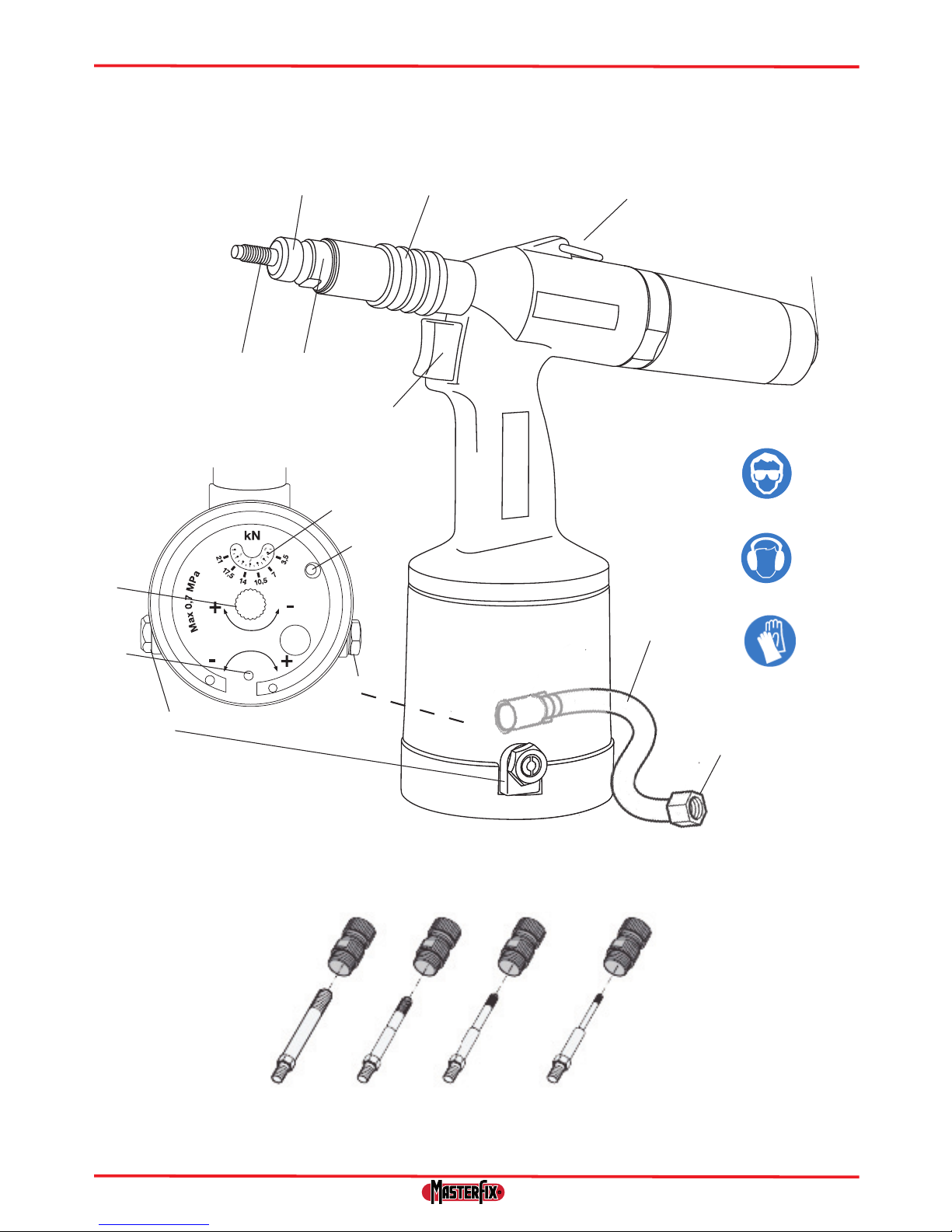
2. Main components
2.1 Components
2.2 Mandrels/Anvils
The delivered box for XGrip N08 QI contains mandrels and anvils M4 - M8.
The delivered box for XGrip N10 QI contains mandrels and anvils M5-M10
Other mandrels and anvils are available seperately.
1. General
1.1 This manual
This manual describes the daily use of the tools. Carefully read this manual. Every user must be acquainted with
the contents of this manual. Strictly follow the instructions in this manual. Always carry out the activities in the correct order. Keep this manual at a xed place. If the manual gets lost, you can download it from www.master x.com.
1.2 Icons in this manual
The following icons and symbols have been used in this manual:
CAUTION!
Procedures requiring extra attention
Read the manual
Use safely goggles
Use hearing protection
Use safety gloves
1.3 Discarding and the environment
Discarded tools are to be disposed of in accordance with the local regulations.
A Mandrel K Needle valve (to set return time)
B Anvil L Pressure gauge
C Nose piece holder M Oil level indicator
D Protective sleeve N Pressured air hose
E Bracket O Air connection
F Release button P Mandrel/Anvil set
G Trigger X Type indication
H Tool - Air connection Y Serial number
I Pressure releave valve
J Pressure adjustment dial
Page 5

XGrip N08QI - XGrip N10QI
3
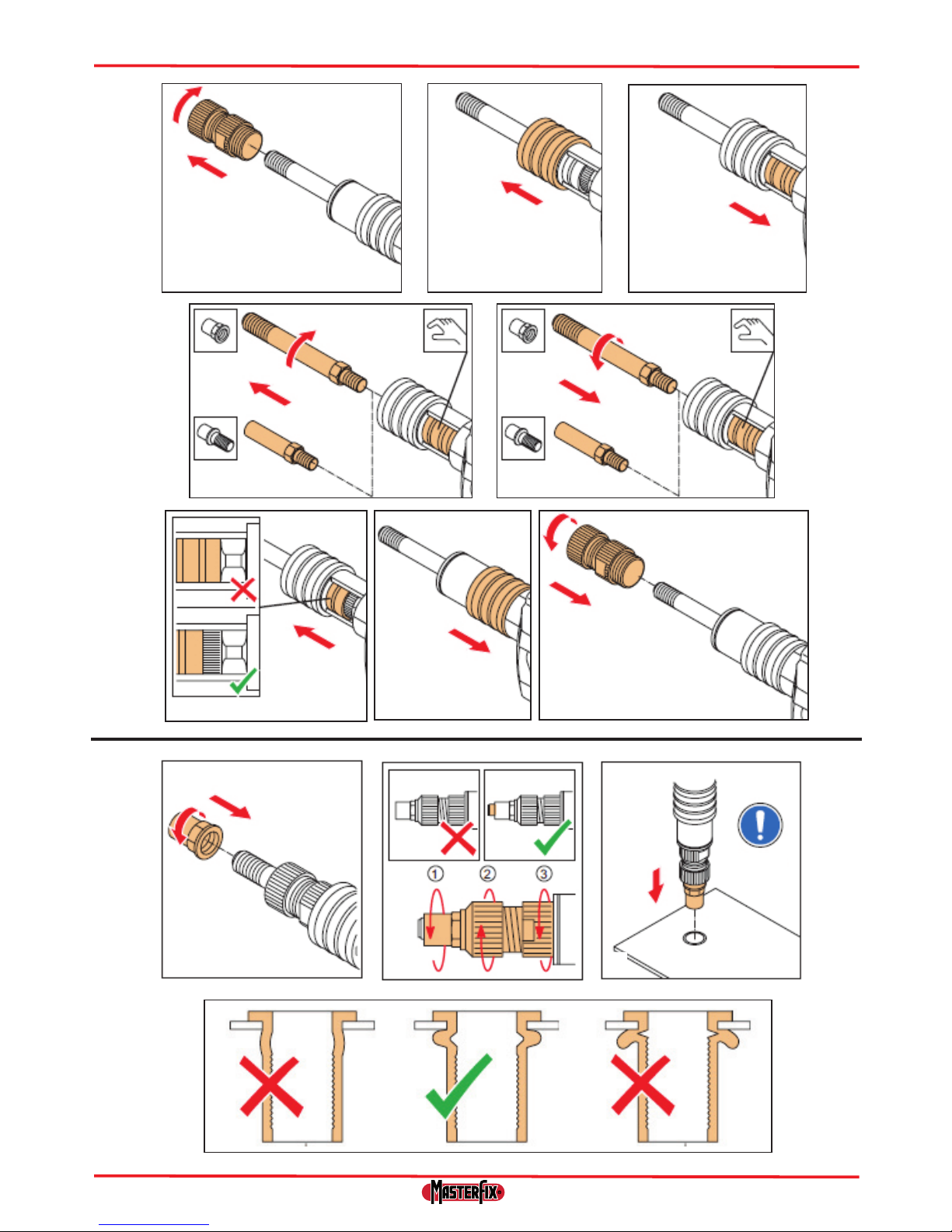
4. Operation
4.1 Fitting the correct mandrel/adapter (see Fig. 2)
4.2 Placing the rivet nut/bolt (see Fig. 3)
4.3 Setting the pressure (see Fig. 1)
• The pressure can be adjusted by the set screw (J) at the bottom of the tool. The tool is set at its minimum
pressure when it leaves the factory.
• Turn the set screw(J) clockwise to increase the pressure. Turn the set screw (J) anti-clockwise to reduce the
pressure. When reducing the pressure, always operate the trigger (G) to let the pressure release.
• The set pressure can be read from the pressure indication (L).
When adjusting the pressure belonging to the nut/bolt:
• rst adjust to the minimum pressure and then slowly increase;
• place a nut/bolt on the mandrel/adapter (A)
• operate the trigger(G) and increase the pressure by turning the set screw(J) clockwise until the nut/bolt
deforms.
If problems should occur with the setting of the pressure, disconnect the tool from the compressed air supply, to
release the tool from the pressure.
3. Safety
3.1 Safety instructions
Read the manual
Use safety goggles. This also applies to persons in the immediate surroundings.
Use hearing protection when the sound level exceeds 85 dB(A).
Use safety gloves.
• Keep your ngers away from the front when connecting the compressed air.
• Never direct the tool at persons.
3.2 Work environment
- Set a constant air pressure to 5 - 7 bars (maximum 7 bars).
•
• Keep the work environment clean and neat.
• Use dry, ltered and with anti-corrosive oillubricated air.
• If not available, put 0.1 ml (approximately 5 drops) of anti- corrosive lubricating oil in air connection of tool
three times each operating day.
• Work in a frost-free environment.
• The connection to the tools is G¼“. A connection nipple has not been included. Provide an appropriate
solution yourself.
3.3 Tools
Never use the tools
- when the anvil (A) is missing;
• Check the tools for damage before connecting the air pressure.
• Keep the tools in an optimum condition.
• Switch o the air supply when the tools are not used.
• Make sure that the exible connection hose (M) is not pressurised when disconnecting.
• Do not modify the tools in any way.
• Only use the device for appropriate purposes
Page 6
XGrip N08QI - XGrip N10QI
4
5. Maintenance
Use safety goggles
Use hearing protection
Use safety gloves
5.1 Regular maintenance
Turn o and disconnect the air supply.
- Check the oil level. There may be insu cient oil if the stroke is too small for proper installation
of the rivet nut or rivet bolt.
- Dismantle anvil(see Fig. 2.1). then clean using an air blow gun and soft cloth.
- Dismantle the mandrel (see Fig. 2.4) clean using an air blow gun and soft cloth.
- Clean front sleeve using an air blow gun and soft cloth.
- Lubricate mandrel after reassembly.
5.2 Major maintenance
Every 100.000 cycles tool must be completely dismantled and all seals and worn parts must be replaced.
This must be done only by a trained engineer or listed service center.
Model XGrip N08QI XGrip N10QI
Weight kg 2,3 2,5
length mm 313 313
Height mm 276 276
Stroke mm 9 max 9 max
Pulling Force N 21000 29800
Rivet nut range nom. dia. M3-M8 M4-M10
6. Technical Data
7. Warranty
This rivet nut tool has a 12 month warranty from the day of delivery (to be proven by invoice
or delivery note). Damage caused by common wearing, overloading or improper handling are
excluded from the warranty. Damages caused by material or manufacturing faults will be covered
by this waranty and will be repaired or replaced at no cost. Claims can only be accepted if the
complete rivet nut tool (not stripped) is returned to the distributor.
Page 7
XGrip N08QI - XGrip N10QI
5
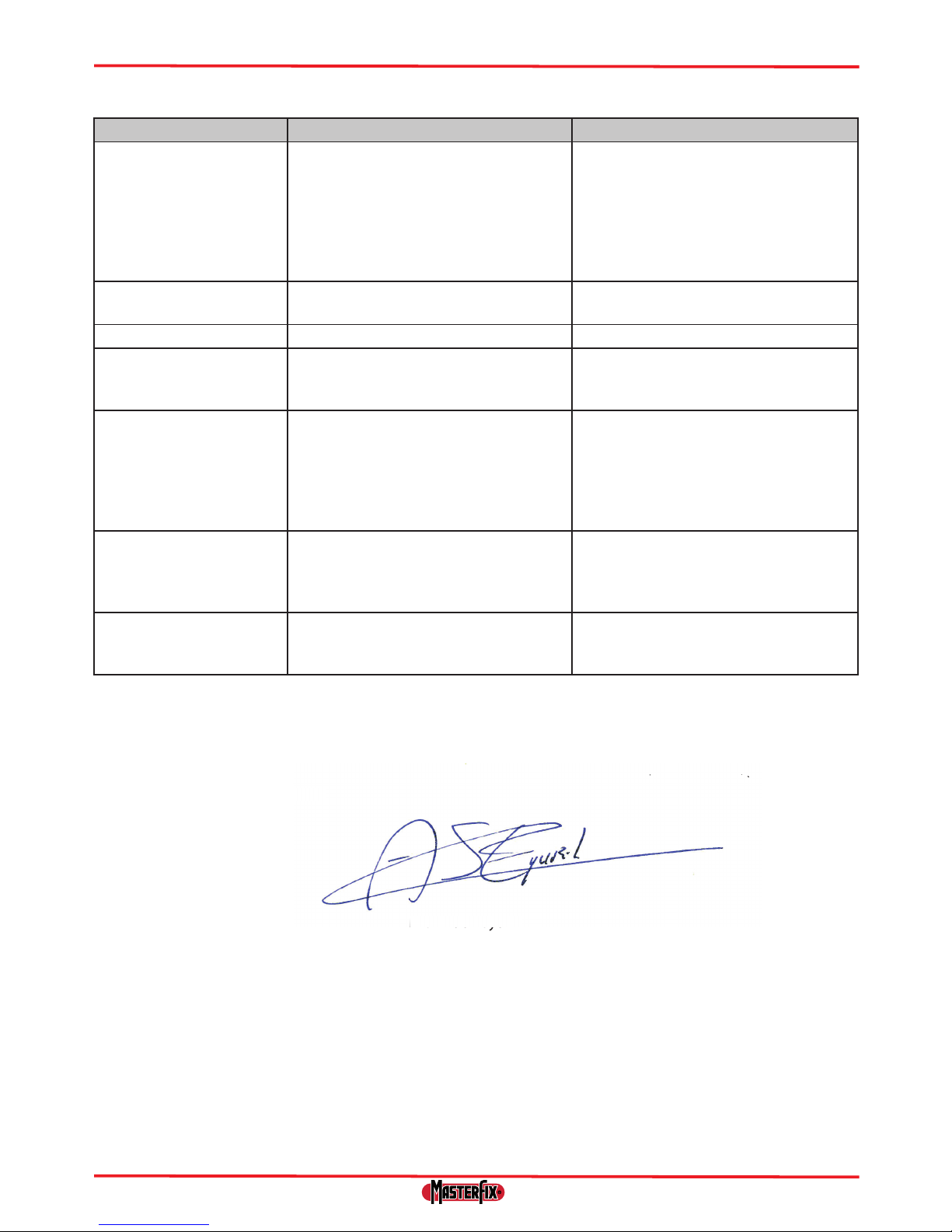
9. CE conformity declaration
We hereby declare under our sole responsibilty that these products meet the following
standards and directives:
• 2006/42/EC
• EN 792-1
Mr. Andor Gyurik
Managing Director
Emhart Teknologies B.V.
Born, The Netherlands: 21-01-2013
Problem Cause Corrective action
The tool does not work The tool has not been connected to the
air connection
The air supply closing valve is still closed
There is insu cient air pressure
Connect the tool to the air
connection
Open the air supply closing valve
Use the correct air pressure 5-7 bar
Air is coming out of the
safety valve
The air pressure is too high Use the correct air pressure 5-7 bar
The trigger does not work There is insu cient air pressure Use the correct air pressure 5-7 bar
The blind rivet nut
cannot be placed onto the
mandrel
The incorrect mandrel/anvil set has been
installed
Install the correct mandrel/anvil set
The blind rivet nut is not
set correctly
Stroke is not set correctly
There is insu cient air pressure
The capacity of the tool has been
exceeded
Set correct stroke
Use the correct air pressure
Use the correct tool
The tool does not
completely release from
the set rivet nut after trigger is released
Rivet nut has not set
correctly
Push release button
The tool does not
perform well
consistently
Requires service Contact a service centre
8. Trouble shooting
nder our sole responsibilty that these productsmeet the followi
n
iv
es:
Page 8

XGrip N08QI - XGrip N10QI
6
Inhalt
1 Allgemeines..................................................................................................................................... 7
2 Hauptkomponenten.................................................................................................................... 7
3 Sicherheit......................................................................................................................................... 8
4 Betrieb............................................................................................................................................... 8
5 Wartung............................................................................................................................................ 9
6. Technische Daten.......................................................................................................................... 9
7 Garantie............................................................................................................................................ 9
8. Fehlerbehebung............................................................................................................................ 10
9. CE-Konformitätserklärung......................................................................................................... 10
10 Schnellanleitung............................................................................................................................ 31
© 2013 Emhart Teknologies B.V.
Alle Rechte vorbehalten.
Die bereitgestellten Informationen dürfen in keinerlei Weise und durch keinerlei Mittel (elektronisch oder mechanisch) vervielfältigt und/oder verö entlicht werden, wenn keine vorherige ausdrückliche und schriftliche Genehmigung von Emhart Teknologies B.V. vorliegt. Die bereitgestellten Informationen stützen sich auf die Daten, die
zum Zeitpunkt der Einführung dieses Produktes bekannt sind. Emhart Teknologies B.V. verfolgt eine Politik der
ständigen Produktverbesserung und somit können die Produkte Änderungen unterliegen.
Die bereitgestellten Informationen gelten für das Produkt wie von Master x Products b.v. geliefert. Daher haftet
Emhart Teknologies B.V. nicht für Schäden, die aus Abweichungen von den ursprünglichen Spezi kationen des
Produkts entstehen.
Die verfügbaren Informationen wurden mit größter Sorgfalt zusammengestellt. Allerdings übernimmt Emhart
Teknologies B.V. keine Haftung für eventuelle Fehler in den Informationen noch für die Folgen davon. Master x
Products b.v. haftet nicht für Schäden, die aus Tätigkeiten entstehen, die von Dritten ausgeführt werden.
Die Arbeitstitel, Handelsnamen, Warenzeichen usw., die von Emhart Teknologies B.V. verwendet werden, dürfen
gemäß den Rechtsvorschriften in Bezug auf den Schutz von Marken nicht als frei angesehen werden.
Page 9
XGrip N08QI - XGrip N10QI
7
2. Hauptkomponenten
2.1 Komponenten
2.2 Dorne/Matrizen
Der Lieferumfang für XGrip N08 QI enthält Gewindedorne/Mundstücke der Größen M4 - M8.
Der Lieferumfang für XGrip N10 QI enthält Gewindedorne/Mundstücke der Größen M5 - M10.
Andere Gewindedorne/Mundstücke sind separat erhältlich.
1. Allgemeines
1.1 Dieses Handbuch
Dieses Handbuch beschreibt den täglichen Gebrauch der Werkzeuge. Lesen Sie dieses Handbuch sorgfältig. Jeder
Benutzer muss mit dem Inhalt dieses Handbuchs vertraut sein. Befolgen Sie die Anweisungen in diesem Handbuch genau. Führen Sie die Tätigkeiten immer in der richtigen Reihenfolge aus. Bewahren Sie dieses Handbuch an
einem festen Platz auf. Wenn das Handbuch verloren geht, können Sie es von www.master x.com herunterladen.
1.2 Symbole in diesem Handbuch
In diesem Handbuch werden die folgenden Symbole und Zeichen verwendet:
VORSICHT!
Verfahren, die besondere Aufmerksamkeit erfordern
Lesen Sie das Handbuch
Tragen Sie eine Schutzbrille
Benutzen Sie einen Gehörschutz
Tragen Sie Schutzhandschuhe
1.3 Entsorgung und die Umwelt
Ausgediente Werkzeuge müssen in Übereinstimmung mit den örtlichen Vorschriften entsorgt werden.
A Gewindedorn K Nadelventil (zum Einstellen der Rücklaufzeit)
B Mundstück L Manometer
C Mundstückaufnahme M Ölstandsanzeige
D Schutzhülle N Druckluftschlauch
E Halterung O Luftanschluss
F Entriegelungstaste P Gewindedorn/Mundstückset
G Auslöser X Typenangabe
H Werkzeug - Luftanschluss Y Seriennummer
I: Druckbegrenzungsventil
J Druckeinstellrad
Page 10
XGrip N08QI - XGrip N10QI
8
4. Betrieb
4.1 Montage des richtigen Gewindedorns/Mundstücks (siehe Abb. 2)
4.2 Einsetzen von Nietmutter/Bolzen (siehe Abb. 3)
4.3 Einstellen des Drucks (siehe Abb. 1)
• Der Druck kann durch die Stellschraube (J) an der Unterseite des Werkzeugs eingestellt werden. Das Werkzeug
ist auf seinen minimalen Druck eingestellt, wenn es das Werk verlässt.
• Drehen Sie die Stellschraube (J) im Uhrzeigersinn, um den Druck zu erhöhen. Drehen Sie die Stellschraube (J)
gegen den Uhrzeigersinn, um den Druck zu verringern. Betätigen Sie beim Reduzieren des Drucks immer den
Auslöser (G), um den Druck zu entlasten.
• Der eingestellte Druck kann an der Druckanzeige (L) abgelesen werden.
Beim Einstellen des Drucks für die Mutter/den Bolzen:
• zuerst bis zum minimalen Druck einstellen und dann langsam steigern;
• eine Mutter/einen Bolzen auf den Dorn/Adapter (A) setzen,
• den Auslöser (G) betätigen und den Druck erhöhen, indem Sie die Stellschraube (J) im Uhrzeigersinn drehen,
bis sich die Mutter/der Bolzen verformt.
Wenn bei der Einstellung des Drucks Probleme auftreten, trennen Sie das Werkzeug von der Druckluftversorgung,
um den Druck aus dem Werkzeug abzulassen.
3. Sicherheit
3.1 Sicherheitshinweise
Lesen Sie das Handbuch
Tragen Sie eine Schutzbrille. Dies gilt auch für Personen in der unmittelbaren Umgebung.
Verwenden Sie einen Gehörschutz, wenn der Schallpegel über 85 dB(A) liegt.
Tragen Sie Schutzhandschuhe.
• Halten Sie Ihre Finger beim Anschließen der Druckluft von der Vorderseite weg.
• Richten Sie das Werkzeug niemals auf Personen.
3.2 Arbeitsumgebung
- Stellen Sie einen konstanten Luftdruck von 5 bis 7 bar (maximal 7 bar) ein.
•
• Halten Sie die Arbeitsumgebung sauber und ordentlich.
• Verwenden Sie trockene, ge lterte und mit antikorrosivem Öl geschmierte Luft.
• Falls diese nicht vorhanden ist, tragen Sie dreimal pro Betriebstag 0,1 ml (ca. 5 Tropfen) antikorrosives Schmieröl auf den Luftanschluss des Werkzeugs auf.
• Arbeiten Sie in einer frostfreien Umgebung.
• Der Werkzeuganschluss hat die Größe G¼“. Ein Anschlussnippel ist nicht enthalten. Stellen Sie selbst eine
angemessene Lösung bereit.
3.3 Werkzeuge
Verwenden Sie die Werkzeuge niemals:
- wenn das Mundstück (A) fehlt;
• Überprüfen Sie die Werkzeuge auf Schäden, bevor Sie die Druckluft anschließen.
• Halten Sie die Werkzeuge in einem optimalen Zustand.
• Schalten Sie die Luftzufuhr ab, wenn die Werkzeuge nicht verwendet werden.
• Stellen Sie sicher, dass der exible Verbindungsschlauch (M) nicht unter Druck steht, wenn Sie den Anschluss lösen.
• Nehmen Sie keinerlei Veränderungen an den Werkzeugen vor.
• Verwenden Sie das Gerät nur für für den vorgesehenen Zweck.
Page 11

XGrip N08QI - XGrip N10QI
9
5. Wartung
Tragen Sie eine Schutzbrille
Benutzen Sie einen Gehörschutz
Tragen Sie Schutzhandschuhe
5.1 Regelmäßige Wartung
Schalten Sie die Luftzufuhr aus und trennen Sie sie ab.
- Überprüfen Sie den Ölstand. Es ist eventuell zu wenig Öl vorhanden, wenn der Hub für die ord-
nungsgemäße Installation der Nietmutter oder des Nietbolzens zu klein ist.
- Mundstück demontieren (siehe Abb. 2.1), dann mit einer Druckluftpistole und einem weichen
Tuch reinigen.
- Gewindedorn demontieren (siehe Abb. 2.4), dann mit einer Druckluftpistole und einem weichen
Tuch reinigen.
- Vordere Hülse mit einer Druckluftpistole und einem weichen Tuch reinigen.
- Gewindedorn nach dem Zusammenbau schmieren.
5.2 Hauptwartung
Nach jeweils 100.000 Zyklen muss das Werkzeug komplett zerlegt und alle Dichtungen und abgenutzte
Teile müssen ausgetauscht werden. Dies darf nur von einer Fachkraft oder einem der aufgeführten Kundendienstzentren durchgeführt werden.
Modell XGrip N08QI XGrip N10QI
Gewicht kg 2,3 2,5
Länge mm 313 313
Höhe mm 276 276
Hub mm max. 9 max. 9
Zugkraft N 21000 29800
Nietmutternbereich Nenndurchm. M3-M8 M4-M10
6. Technische Daten
7. Gewährleistung
Dieses Nietmutternwerkzeug verfügt über eine 12-monatige Gewährleistung ab dem Tag der
Lieferung (durch Rechnung oder Lieferschein nachzuweisen). Schäden, die durch üblichen Verschleiß, Überlastung oder unsachgemäße Behandlung entstehen, sind von der Gewährleistung
ausgeschlossen. Schäden, die durch Material- oder Fabrikationsfehler verursacht werden, sind von
dieser Gewährleistung abgedeckt und werden unentgeltlich repariert oder ersetzt. Beanstandungen können nur anerkannt werden, wenn das gesamte Nietmutternwerkzeug (nicht zerlegt) an
den Händler zurückgegeben wird.
Page 12

XGrip N08QI - XGrip N10QI
10
9. CE-Konformitätserklärung
Wir erklären hiermit in unserer alleinigen Verantwortung, dass diese Produkte die folgenden
Normen und Richtlinien erfüllen:
• 2006/42/EC
• EN 792-1
Herr Andor Gyurik
Managing Director
Emhart Teknologies B.V.
Born, The Netherlands: 21-01-2013
Problem Ursache Abhilfemaßnahme
Das Werkzeug funktioniert
nicht
Das Werkzeug ist nicht an den Luftanschluss angeschlossen
Das Luftzufuhrventil ist noch geschlossen
Es ist zu wenig Luftdruck vorhanden
Schließen Sie das Werkzeug an
die Luftzufuhr an
Ö nen Sie das Luftzufuhrventil
Verwenden Sie den richtigen Luftdruck
von 5-7 bar
Luft tritt aus dem Sicherheitsventil aus
Der Luftdruck ist zu hoch Verwenden Sie den richtigen Luftdruck
von 5-7 bar
Der Auslöser funktioniert
nicht
Es ist zu wenig Luftdruck vorhanden Verwenden Sie den richtigen Luftdruck
von 5-7 bar
Die Blindnietmutter kann
nicht auf den Dorn gesetzt
werden
Das falsche Gewindedorn/Mundstückset
wurde installiert
Installieren Sie das richtige Gewindedorn/Mundstückset
Die Blindnietmutter ist
nicht richtig eingesetzt
Der Hub ist nicht richtig eingestellt
Es ist zu wenig Luftdruck vorhanden
Die Kapazität des Werkzeugs wurde
überschritten
Richtigen Hub einstellen
Verwenden Sie den richtigen Luftdruck
Verwenden Sie das richtige Werkzeug
Das Werkzeug löst sich
nicht vollständig von der
eingesetzten Nietmutter,
nachdem der Auslöser
losgelassen wird
Nietmutter ist nicht korrekt eingesetzt Entriegelungstaste drücken
Das Werkzeug funktioniert
nicht immer gleich gut
Wartung erforderlich Kontaktieren Sie den Kundendienst
8. Fehlersuche
i
n unserer alleinigen
V
er
antwortu
, dass diese Produkte die fo
lg
e
rfüll
e
n:
Herr Andor Gyuri
k
Page 13

XGrip N08QI - XGrip N10QI
11
Table des matières
1 Généralités....................................................................................................................................... 12
2 Principaux composants............................................................................................................... 12
3 Sécurité............................................................................................................................................. 13
4 Fonctionnement............................................................................................................................ 13
5 Entretien........................................................................................................................................... 13
6 Caractéristiques techniques...................................................................................................... 14
7 Garantie............................................................................................................................................ 14
8 Dépannage...................................................................................................................................... 15
9 Déclaration de conformité CE................................................................................................. 15
10 Utilisation rapide........................................................................................................................... 31
© 2013 Emhart Teknologies B.V.
Tous droits réservés.
Les informations fournies ne doivent pas être reproduites et/ou divulguées, quelque soit la manière ou le moyen
(électronique ou mécanique) sans l'accord explicite préalable par écrit de la part d'Emhart Teknologies B.V. Les informations fournies se basent sur les données connues au moment de la commercialisation de ce produit. Emhart
Teknologies B.V. adopte une politique d'amélioration permanente de ses produits et ces derniers peuvent donc
faire l'objet de modi cations.
Les informations fournies s'appliquent au produit livré par Master x Products bv. Par conséquent, Emhart Teknologies B.V. ne saurait être tenu responsable des dégâts résultant de di érences avec les spéci cations d'origine du
produit.
Les informations disponibles ont été rédigées avec le plus grand soin. Toutefois, Emhart Teknologies B.V. rejettera
toute responsabilité en cas d'erreur dans les informations ou pour les conséquences de leur utilisation. Master x
Products bv rejettera toute responsabilité quant aux dégâts résultant des activités e ectuées par des tiers.
Les noms provisoires, noms commerciaux, marques déposées, etc. utilisés par Emhart Teknologies B.V. ne doivent
pas être considérés libres, conformément à la législation relative à la protection des marques de commerce.
Page 14

XGrip N08QI - XGrip N10QI
12
2. Principaux composants
2.1 Composants
2.2 Mandrins/enclumes
La boîte fournie pour le XGrip N08 QI contient des mandrins et enclumes M4 - M8.
La boîte fournie pour le XGrip N10 QI contient des mandrins et enclumes M8 - M10.
D’autres mandrins et enclumes sont disponibles en accessoires optionnels.
1. Généralités
1.1 Ce manuel
Ce manuel décrit l'utilisation quotidienne des outils. Lisez attentivement ce manuel. Chaque utilisateur doit se familiariser avec le contenu de ce manuel. Suivez scrupuleusement les instructions de ce manuel. E ectuez toujours
les activités dans l'ordre correct. Conservez ce manuel au même endroit. Si le manuel est perdu, vous pouvez le
télécharger depuis le site www.master x.com.
1.2 Icônes dans ce manuel
Les icônes et symboles suivants ont été utilisés dans ce manuel:
ATTENTION!
Procédures exigeant une attention particulière
Lisez le manuel
Utilisez des lunettes de sécurité
Utilisez une protection auditive
Utilisez des gants de sécurité
1.3 Mise au rebut et environnement
Les outils qui ne sont plus utilisés doivent être mis au rebut conformément aux réglementations locales.
A Mandrin K Pointeau (pour régler le temps de retour)
B Enclume L Manomètre
C Porte-embout M Indicateur de niveau d'huile
D Manchon de protection N Tuyau d'air comprimé
E Support O Tuyau d’alimentation pneumatique
F Bouton de dévissage forcé P Ensemble mandrin/enclume
G Gâchette X Indication de type
H Raccord pneumatique de l'outil Y Numéro de série
I Soupape de décharge
J Cadran de réglage de la pression
Page 15

XGrip N08QI - XGrip N10QI
13
4. Fonctionnement
4.1 Montage du mandrin/adaptateur correct (voir Fig. 2)
4.2 Mise en place de l’écrou/goujon à sertir (voir Fig. 3)
4.3 Réglage de la pression (voir Fig. 1)
• La pression se règle avec la vis de réglage (J) au bas de l'outil. L'outil est réglé à la pression minimale lorsqu'il
quitte l'usine.
• Tournez la vis de réglage (J) à droite pour augmenter la pression. Tournez la vis de réglage (J) à gauche pour diminuer la pression. Lorsque vous réduisez la pression, actionnez toujours la gâchette (G) pour purger la pression.
• La pression réglée peut être lue sur l'indicateur de pression (L).
Lors du réglage de la pression pour l’écrou/goujon :
• réglez d'abord la pression minimale, puis augmentez lentement;
• placez un écrou/goujon sur le mandrin/adaptateur (A)
• actionnez la gâchette (G) et augmentez la pression en tournant la vis de réglage (J) à droite jusqu’à ce que
l’écrou/goujon se déforme.
En cas de problème avec le réglage de la pression, déconnectez l'outil de l'alimentation d'air comprimé pour purger la pression de l'outil.
3. Sécurité
3.1 Consignes de sécurité
Lisez le manuel
Utilisez des lunettes de sécurité. Cette consigne est également valable pour les personnes à proximité
immédiate.
Utilisez une protection auditive lorsque le niveau de bruit dépasse 85dB(A).
Utilisez des gants de sécurité.
• Tenez les doigts éloignés de l'avant de l'outil lors du raccordement de l'air comprimé.
• Ne dirigez jamais l'outil vers les personnes.
3.2 Environnement de travail
- Régler une pression d'air constante à 5 - 7 bars (maximum 7 bars).
•
• Maintenez l'environnement de travail propre et ordonné.
• Utilisez de l’air ltré et lubri é avec de l’huile anticorrosion.
• En cas d'indisponibilité, mettez 0,1ml (environ 5 gouttes) d'huile de lubri cation anticorrosion dans le raccord
pneumatique de l'outil trois fois par jour.
• Travaillez dans un lieu à l'abri du gel.
• Le raccord des outils est de type G¼“. Aucun mamelon de connexion n’est fourni. Charge à l’Utilisateur de raccorder l’outil au réseau pneumatique de manière appropriée.
3.3 Outils
N'utilisez jamais les outils
- si l'enclume (A) est absente;
• Contrôlez l’état général de l’outil avant de le raccorder l’air comprimé.
• Maintenez les outils en excellent état.
• Désactivez l'alimentation de l'air lorsque les outils ne sont pas utilisés.
• Assurez-vous que le exible de connexion (M) n'est pas sous pression avant de le déconnecter.
• Ne modi ez jamais les outils.
• Utilisez exclusivement l'appareil conformément aux usages prévus.
Page 16

XGrip N08QI - XGrip N10QI
14
5. Entretien
Utilisez des lunettes de sécurité
Utilisez une protection auditive
Utilisez des gants de sécurité
5.1 Entretien ordinaire
Désactivez et déconnectez l'alimentation d'air.
- Véri ez le niveau d’huile. Le niveau d’huile peut être insu sant si la course est trop faible pour
une installation correcte de l’écrou ou du goujon à sertir.
-
Démontez l'enclume (voir Fig. 2.1), puis nettoyez avec un pistolet à air comprimé et un chi on doux.
- Démontez le mandrin (voir Fig. 2.4) et nettoyez avec un pistolet à air comprimé et un chi on doux.
- Nettoyez le manchon avant avec un pistolet à air comprimé et un chi on doux.
- Lubri ez le mandrin après le remontage.
5.2 Entretien extraordinaire
Tous les 100000 cycles, l'outil doit être complètement démonté et tous les joints et pièces d'usure
doivent être remplacés. Cette opération doit être réalisée par un technicien formé ou l'un des centres de
services indiqués.
Modèle XGrip N08QI XGrip N10QI
Poids kg 2,3 2,5
longueur mm 313 313
Hauteur mm 276 276
Course mm 9 max 9 max
Force de traction N 21000 29800
Gamme d’écrou à sertir dia. nom. M3-M8 M4-M10
6. Caractéristiques techniques
7. Garantie
Cet outil pour écrou à riveter est couvert par une garantie de 12 mois à compter de la date de
livraison (la facture ou le bon de livraison doivent être présentés). Les dégâts causés par l’usure
normale, la surcharge ou toute manipulation incorrecte sont exclus de la garantie. Les dégâts causés par des défauts de matériel ou de fabrication seront couverts par cette garantie feront l’objet
d’une réparation ou d’un remplacement à titre gratuit. Les réclamations ne pourront être acceptées que si l’outil pour écrou à riveter complet (non démonté) est renvoyé au distributeur.
Page 17

XGrip N08QI - XGrip N10QI
15
9. Déclaration de conformité CE
Nous déclarons par la présente sous notre unique responsabilité que ces produits sont conformes
aux normes et directives suivantes:
• 2006/42/EC
• EN 792-1
Mr. Andor Gyurik
Directeur général
Emhart Teknologies B.V.
Born, The Netherlands: 21-01-2013
Problème Cause Action corrective
L'outil ne fonctionne pas L'outil n'a pas été raccordé à la
connexion pneumatique
La soupape d'arrêt d'alimentation d'air
est encore fermée
La pression de l'air est insu sante
Raccordez l'outil à la connexion
pneumatique
Ouvrez la soupape d'arrêt d'alimentation
d'air
Utilisez la pression d'air correcte de 5-7 bar
L'air sort de la
soupape de sûreté
La pression de l'air est trop élevée Utilisez la pression d'air correcte de 5-7 bar
La gâchette ne fonctionne pas
La pression de l'air est insu sante Utilisez la pression d'air correcte de 5-7 bar
L’écrou à sertir ne peut
pas être placé sur le
mandrin
Un ensemble mandrin/enclume incorrect a été installé
Installez l'ensemble mandrin/enclume
correct
L’écrou à sertir n’est pas
placé correctement
La course n'est pas réglée correctement
La pression de l'air est insu sante
La capacité de l'outil a été dépassée
Réglez la course correcte
Utilisez la pression d'air correcte
Utilisez l'outil correct
L'outil ne se libère pas
complètement de l'écrou
riveté après avoir relâché
la gâchette
L’écrou n’a pas été serti correctement Appuyez sur le bouton de dévissage forcé
L'outil ne fonctionne pas
correctement de manière
régulière
Révision nécessaire Contactez un centre de service
8. Dépannage
a ésente sous notre
un
iq
ue res
nsa
bilité
que ces
oduits so
n
essuivant
es
Mr. Andor G
y
ur
i
k
Page 18

XGrip N08QI - XGrip N10QI
16
Contenido
1 General............................................................................................................................................. 17
2 Componentes principales......................................................................................................... 17
3 Seguridad......................................................................................................................................... 18
4 Funcionamiento............................................................................................................................. 18
5 Mantenimiento.............................................................................................................................. 19
6. Datos técnicos................................................................................................................................ 19
7 Garantía............................................................................................................................................. 19
8. Resolución de problemas........................................................................................................... 20
9. Declaración de conformidad CE............................................................................................. 20
10 Uso rápido........................................................................................................................................ 31
© 2013 Emhart Teknologies B.V.
Todos los derechos reservados.
La información proporcionada no se podrá reproducir y/ohacer pública bajo ningún concepto ypor ningún medio
(electrónico omecánico) sin autorización previa, explicita ypor escrito, de Emhart Teknologies B.V. Dicha información se basa en los datos conocidos hasta el momento de introducción de este producto. Emhart Teknologies B.V.
aplica una política de mejora continua de producto, por lo tanto, los productos están sujetos amodi caciones.
La información facilitada es de aplicación al producto tal ycomo ha sido entregado por Master x Products bv. Por
tanto, Emhart Teknologies B.V. no se responsabilizará de ningún daño derivado de Disconformidades con las especi caciones originales del producto.
La información disponible ha sido elaborada con extrema diligencia. No obstante, Emhart Teknologies B.V. no
asumirá responsabilidad alguna en relación con cualesquiera fallos en la información olas consecuencias que pudieran derivarse de los mismos. Master x Products bv no asumirá responsabilidad alguna por daños derivados de
actividades efectuadas por terceros.
Las denominaciones provisionales, denominaciones comerciales, marcas comerciales registradas, etc. usadas por
Emhart Teknologies B.V. no deberán considerarse libres en virtud de la legislación relativa aprotección de marcas
comerciales.
Page 19

XGrip N08QI - XGrip N10QI
17
2. Componentes principales
2.1 Componentes
2.2 Mandriles/Boquillas
La caja suministrada con la remachadora XGrip N08 QI contiene mandriles yboquillas M4 - M8.
La caja suministrada con la remachadora XGrip N10 QI contiene mandriles yboquillas M5 - M10
Otros mandriles yboquillas se pueden comprar por separado.
1. General
1.1 Este manual
Este manual describe el uso diario de las herramientas. Léalo atentamente. Todos los usuarios deben tener conocimiento de los contenidos de este manual. Siga estrictamente las instrucciones del manual. Efectúe siempre
las actividades en el orden correcto. Guarde este manual en un lugar establecido. Si pierde este manual, puede
descargarlo de www.master x.com.
1.2 Figuras del manual
En el presente manual se usan las siguientes guras ysímbolos:
CUIDADO
Procedimientos que requieren especial atención
Lea el manual
Use gafas protectoras de seguridad
Use protector auditivo
Use guantes de protección
1.3 Eliminación ymedioambiente
Las herramientas desechadas deberán eliminarse de acuerdo con las normas locales.
A Mandril K Válvula de aguja (para establecer intervalo de
retroceso)
B Boquilla L Manómetro
C Portaboquillas M Indicador del nivel del aceite
D Manguito de protección N Manguera de aire comprimido
E Soporte O Conexión de aire
F Botón de liberación P Juego mandril/boquilla
G Gatillo X Indicación del tipo
H Conexión herramienta - aire Y Número de serie
I Válvula de descarga de presión
J Botón giratorio de ajuste de presión
Page 20

XGrip N08QI - XGrip N10QI
18
4. Funcionamiento
4.1 Colocación del mandril/adaptador correcto (véase la Fig. 2)
4.2 Colocación de la tuerca/tornillo remachable correcto (véase la Fig. 3)
4.3 Ajuste de la presión (véase la Fig. 1)
• La presión puede ajustarse usando el tornillo de ajuste (J) que se encuentra en la parte inferior de la herramienta. La herramienta sale ajustada de fábrica ala presión mínima.
• Gire el tornillo de ajuste (J) en sentido horario para aumentar la presión. Gire el tornillo de ajuste (J) en sentido
antihorario para disminuir la presión. Al reducir la presión, apriete siempre el gatillo (G) para dejar salir la presión.
• La presión establecida puede leerse en el indicador de presión (L).
Para ajustar la presión de la tuerca/tornillo:
• Primero ajuste la presión al mínimo ydespués vaya aumentándola lentamente,
• coloque una tuerca/tornillo en el mandril/adaptador (A)
• apriete el gatillo(G) yaumente la presión girando el tornillo de ajuste (J) en sentido horario hasta que la tuerca/
tornillo se deforme.
Si surge algún problema al ajustar la presión, desconecte la herramienta del suministro de aire comprimido para
interrumpir la presión de la herramienta.
3. Seguridad
3.1 Instrucciones de seguridad
Lea el manual
Use gafas protectoras de seguridad. Esto vale también para las personas que se encuentren cerca del lugar.
Use protector auditivo cuando el nivel de ruido exceda los 85 dB(A).
Use guantes de protección
• Mantenga los dedos alejados del frente cuando conecte el aire comprimido.
• Nunca dirija la herramienta hacia ninguna persona.
3.2 Entorno de trabajo
- Ajuste una presión de aire constante de 5 - 7 bares (máximo 7 bares).
•
• Mantenga limpio yordenado el entorno de trabajo.
• Use aire seco, ltrado ylubricado con aceite antioxidante.
• Si no dispone de este, coloque 0.1 ml (aproximadamente 5 gotas) de aceite lubricante antioxidante en la conexión de aire de la herramienta tres veces por día de funcionamiento.
• Trabaje en entornos libres de heladas.
• La conexión alas herramientas es G¼". No se incluye niple de conexión, por lo tanto deberá dotarse de uno
apropiado.
3.3 Herramientas
Nunca use las herramientas
si falta la boquilla (A).
• Compruebe que las herramientas no presenten daños antes de conectar la presión del aire.
• Mantenga las herramientas en óptimas condiciones.
• Interrumpa el suministro de aire cuando no use la herramienta.
• Asegúrese de que la manguera de conexión (M) no esté bajo presión al desconectarla.
• No altere las herramientas de ningún modo.
• Utilice el dispositivo únicamente para las nalidades apropiadas.
Page 21

XGrip N08QI - XGrip N10QI
19
5. Mantenimiento
Use gafas protectoras de seguridad
Use protector auditivo
Use guantes de protección
5.1 Mantenimiento ordinario
Apague ydesconecte el suministro de aire.
- Compruebe el nivel de aceite. Si la carrera es demasiado breve para jar correctamente la tuerca
otornillo remachable, puede deberse afalta de aceite.
-
Desmonte la boquilla (véase la Fig. 2.1) ylímpiela mediante soplado de aire ycon un paño suave.
- Desmonte el mandril (véase la Fig. 2.4) ylímpielo mediante soplado de aire ycon un paño suave.
- Limpie el manguito frontal mediante soplado de aire yun paño suave.
- Lubrique el mandril antes de volver aarmar.
5.2 Mantenimiento extraordinario
Cada 100.000 ciclos debe desmontarse completamente la herramienta ydeben sustituirse todas las juntas ylas piezas desgastadas. Esta operación deberá ser efectuada únicamente por un técnico especializado ocentro de asistencia técnica autorizado.
Modelo XGrip N08QI XGrip N10QI
Peso kg 2,3 2,5
longitud mm 313 313
altura mm 276 276
Carrera mm 9 máx. 9 máx.
Fuerza de tracción N 21000 29800
Rango de tuerca remachable Diám. nom. M3-M8 M4-M10
6. Datos técnicos
7. Garantía
Esta remachadora de tuercas remachables posee una garantía de 12 meses de duración apartir
de la fecha de entrega (demostrable mediante factura oalbarrán). Los daños causados por el desgaste normal, sobrecarga omanejo inapropiado se excluyen de la garantía. Los daños causados
por fallos de material ofabricación estarán cubiertos por la garantía ylas piezas serán reparadas
osustituidas gratuitamente. Las reclamaciones serán aceptadas únicamente si se envía la remachadora de tuercas remachables completa (sin desmontar) al distribuidor.
Page 22

XGrip N08QI - XGrip N10QI
20
9. Declaración de conformidad CE
Por la presente declaramos bajo nuestra exclusiva responsabilidad que estos productos satisfacen
las siguientes normas ydirectivas:
• 2006/42/EC
• EN 792-1
D. Andor Gyurik
Consejero delegado
Emhart Teknologies B.V.
Born, The Netherlands: 21-01-2013
Problema Causa Acción correctiva
La herramienta no funcio-naLa herramienta no está conectada ala
conexión de aire
La válvula de cierre del suministro de
aire aún está cerrada
No hay su ciente presión de aire
Conectar la herramienta ala
red de aire
Abra la válvula de cierre del suministro de
aire
Use la presión de aire correcta de 5-7 bares
El aire sale por la
válvula de seguridad
La presión del aire es demasiado alta Use la presión de aire correcta de 5-7 bares
El gatillo no funciona No hay su ciente presión de aire Use la presión de aire correcta de 5-7 bares
No se puede colocar la
tuerca remachable ciega
en el mandril
Se ha instalado un juego mandril/boquilla incorrecto
Instalar el juego mandril/boquilla correcto
La tuerca remachable ciega no está correctamente
jada
La carrera no está correctamente ajustada
No hay su ciente presión de aire
Se ha excedido la capacidad
de la herramienta
Ajuste correctamente la carrera
Use la presión de aire correcta
Use la herramienta correcta
La herramienta no se libera
totalmente de la tuerca
remachable jada después
de soltar el gatillo
La tuerca remachable no se ha jado
correctamente
Pulse el botón de liberación
La herramienta no funciona continuamente en
modo correcto
Se requiere asistencia técnica Póngase en contacto con un centro de
asistencia técnica
8. Resolución de problemas
ramos bajo nuestra exclusiva responsa
bilidad
que estos pro
d
t
s ydirectivas
:
D. Andor G
yu
ri
k
Page 23

XGrip N08QI - XGrip N10QI
21
Inhoud
1 Algemeen......................................................................................................................................... 22
2 Hoofdcomponenten.................................................................................................................... 22
3 Veiligheid.......................................................................................................................................... 23
4 Gebruik............................................................................................................................................. 23
5 Onderhoud...................................................................................................................................... 24
6. Technische gegevens................................................................................................................... 24
7 Garantie............................................................................................................................................ 24
8. Probleemoplossing....................................................................................................................... 25
9. CE conformiteitsverklaring........................................................................................................ 25
10 Snel gebruik.................................................................................................................................... 31
© 2013 Emhart Teknologies B.V.
Alle rechten voorbehouden.
De verstrekte informatie mag geenszins worden verveelvoudigd en/of openbaar gemaakt op welke wijze
en met welke middelen dan ook (elektronisch of mechanisch), zonder voorafgaande uitdrukkelijke en schriftelijke
toestemming van Emhart Teknologies B.V. De verstrekte informatie is gebaseerd op de gegevens die bekend waren op het moment van het verschijnen van het product. Emhart
Teknologies B.V.voert een beleid van continue productverbetering, wijzigingen zijn derhalve voorbehouden.
De verstrekte informatie is geldig voor het product zoals dit door Master x Products bv is geleverd. Emhart Teknologies B.V. kan derhalve niet aansprakelijk worden gesteld voor eventuele schade voortvloeiend uit afwijkingen
van de oorspronkelijke speci caties van het product.
De beschikbare informatie is met alle mogelijke zorg samengesteld. Emhart Teknologies B.V. kan niet aansprakelijk
worden gesteld voor eventuele fouten in de informatie of voor de gevolgen daarvan. Master x Products bv kan
niet aansprakelijk gesteld worden voor schade voortvloeiend uit werkzaamheden die door derden zijn uitgevoerd.
De door Emhart Teknologies B.V. gebruikte gebruiksnamen, handelsnamen, geregistreerde handelsmerken, etc.
mogen krachtens de wetgeving inzake de bescherming van handelsmerken niet als vrij worden beschouwd.
Page 24

XGrip N08QI - XGrip N10QI
22
2. Hoofdcomponenten
2.1 Componenten
2.2 Draadstiften/Aambeelden
De geleverde doos met de XGrip N08 QI bevat draadstiften en aambeelden M4 - M8.
De geleverde doos met de XGrip N10 QI bevat draadstiften en aambeelden M5 - M10.
Andere draadstiften en aambeelden zijn apart verkrijgbaar.
1. Algemeen
1.1 Deze handleiding
Deze handleiding beschrijft het dagelijks gebruik van het gereedschap. Lees deze handleiding zorgvuldig door.
Elke gebruiker moet van de inhoud van deze handleiding op de hoogte zijn. Volg de aanwijzingen in deze handleiding nauwkeurig op. Verricht de handelingen altijd in de juiste volgorde. Bewaar deze handleiding op een vaste
plaats. Mocht de handleiding zoek raken, kunt u deze downloaden via www.master x.com.
1.2 Pictogrammen in deze handleiding
In deze handleiding zijn de volgende pictogrammen en symbolen gebruikt:
LET OP!
Procedures die extra aandacht vragen
Lees de handleiding
Gebruik veiligheidsbril
Gebruik gehoorbescherming
Gebruik veiligheidshandschoenen
1.3 Afdanken en het milieu
Afgedankt gereedschap moet volgens de lokaal geldende voorschriften worden afgevoerd.
A Draadstift K Naaldventiel (om de terugslagtijd in te stellen)
B Aambeeld L Manometer
C Neusstukhouder M Oliepeil indicator
D Beschermhuls N Luchtdrukslang
E Ophangbeugel O Luchtaansluiting
F Ontgrendelingsknop P Draadstift/Aambeeld set
G Bedieningsschakelaar X Type indicatie
H Luchtaansluiting Y Serienummer
I Overdruk-/beveiligingsventiel
J Luchtdruk instelschroef
Page 25

XGrip N08QI - XGrip N10QI
23
4. Gebruik
4.1 De juiste draadstift/adapter monteren (zie Afb. 2)
4.2 De klinkmoer/bout plaatsen (zie Afb. 3)
4.3 De luchtdruk instellen (zie Afb. 1)
• De luchtdruk kan worden ingesteld met de stelschroef (J) aan de onderkant van het gereedschap. Het gereedschap staat op de laagste stand ingesteld wanneer deze de fabriek verlaat.
• Draai de stelschroef (J) met de klok mee om de druk te verhogen. Draai de stelschroef (J) tegen de klok in om de
druk te verlagen. Bedien tijdens het verlagen van de druk altijd de Bedieningsschakelaar (G) om de druk uit te
laten vloeien.
• De ingestelde druk kan worden afgelezen op de Manometer (L).
Tijdens het instellen van de druk op de moer/bout:
• stel eerst de minimale druk in en verhoog de druk daarna langzaam;
• plaats een moer/bout op de draadstift/adapter (A)
• bedien de Schakelaar (G) en verhoog de druk door de stelschroef (J) met de klok mee te draaien, tot de moer/
bout vervormt.
Wanneer er zich problemen voordoen tijdens het instellen van de druk, ontkoppel dan het gereedschap van de
luchttoevoer om het gereedschap van de druk te ontkoppelen.
3. Veiligheid
3.1 Veiligheidsinstructies
Lees de handleiding
Gebruik een veiligheidsbril. Dit is ook van toepassing op personen in de nabije omgeving.
Gebruik gehoorbescherming wanneer het geluidsniveau 85 dB(A) overschrijd.
Gebruik veiligheidshandschoenen.
• Houdt uw vingers weg van de voorkant tijdens het aansluiten van de luchtdruk.
• Richt het gereedschap nooit op personen.
3.2 Werkomgeving
- Stel een constante luchtdruk in van 5 - 7 bar (maximaal 7 bar).
•
• Houd de werkomgeving schoon en netjes.
• Gebruik droge, ge lterde en met anticorrosie-olie gesmeerde lucht.
• Indien niet beschikbaar, deponeer drie maal per arbeidsdag 0,1 ml (ongeveer 5 druppels) anticorrosie-olie in
de luchtaansluiting van het gereedschap.
• Werk in een vorstvrije omgeving.
• De aansluiting op het gereedschap is G¼“. Een aansluitnippel is niet bijgevoegd. Zorg zelf voor een passende oplossing.
3.3 Gereedschappen
Gebruik het gereedschap niet
- als het aambeeld (A) ontbreekt;
• Controleer het gereedschap op schade voordat u het aansluit op de luchtdruk.
• Houd het gereedschap in optimale toestand.
• Schakel de luchttoevoer uit als het gereedschap niet wordt gebruikt.
• Zorg ervoor dat de exibele slang (N) niet onder druk staat tijdens het ontkoppelen.
• Maak nooit wijzigingen aan het gereedschap.
• Gebruik het gereedschap alleen voor geschikte doeleinden
Page 26

XGrip N08QI - XGrip N10QI
24
5. Onderhoud
Gebruik veiligheidsbril
Gebruik gehoorbescherming
Gebruik veiligheidshandschoenen
5.1 Regelmatig onderhoud
Schakel het gereedschap uit en ontkoppel de luchttoevoer.
- Controleer het oliepeil. Er kan te weinig olie aanwezig zijn als de slag te klein is voor normale
plaatsing van de klinkmoer of klinkbout.
- Demonteer het aambeeld (zie Afb. 2.1). en reinig het met een luchtpistool en zachte doek.
- Demonteer de draadstift (zie Afb. 2.4). en reinig het met een luchtpistool en zachte doek.
- Reinig de Beschermhuls met een luchtpistool en zachte doek.
- Smeer de draadstift na het hermonteren.
5.2 Groot onderhoud
Iedere 100.000 slagen moet het gereedschap volledig worden gedemonteerd en moeten alle sluitingen
en versleten onderdelen worden vervangen. Dit mag alleen worden gedaan door een opgeleide monteur of geregistreerd servicecentrum.
Model XGrip N08QI XGrip N10QI
Gewicht kg 2,3 2,5
lengte mm 313 313
Hoogte mm 276 276
Slag mm 9 max 9 max
Trekkracht N 21000 29800
Klinkmoer afmetingen nom. dia. M3-M8 M4-M10
6. Technische gegevens
7. Garantie
Dit klinkmoer gereedschap heeft een garantie periode van 12 maanden vanaf de a everingsdatum (aangetoond door factuur of a everingsbewijs). Schade veroorzaakt door normale slijtage,
overbelasting of verkeerd gebruik vallen niet onder de garantievoorwaarden. Schade veroorzaakt
door materiële of fabrieksfouten worden gedekt door deze garantievoorwaarden en worden zonder kosten gerepareerd of vervangen. Er kan alleen aanspraak worden gemaakt op de garantie
als het volledige gereedschap (niet gedemonteerd) aan de distributeur wordt geleverd.
Page 27

XGrip N08QI - XGrip N10QI
25
9. CE conformiteitsverklaring
Hierbij verklaren wij onder onze eigen verantwoordelijkheid dat deze producten voldoen aan de
volgende standaarden en richtlijnen:
• 2006/42/EC
• NEN-EN 792-1
Mr. Andor Gyurik
Managing Director
Emhart Teknologies B.V.
Born, The Netherlands: 21-01-2013
Probleem Oorzaak Hoe te verhelpen
Het gereedschap werkt
niet
Het gereedschap is niet aangesloten op
de luchttoevoer
Het luchttoevoerventiel is nog gesloten
Er is onvoldoende luchtdruk
Sluit het gereedschap aan op de luchttoevoer verbinding
Open het luchttoevoerventiel
Gebruik de juiste luchtdruk 5-7 bar
Er komt lucht uit het veiligheidsventiel
De luchtdruk is te hoog Gebruik de juiste luchtdruk 5-7 bar
De Bedieningsschakelaar
werkt niet
Er is onvoldoende luchtdruk Gebruik de juiste luchtdruk 5-7 bar
De blindklinkmoer kan niet
op de draadstift worden
geplaatst
De verkeerde draadstift/aambeeld is
gemonteerd
Monteer de juiste draadstift/aambeeld
De blindklinkmoer is niet
juist geplaatst
De slag is niet juist ingesteld
Er is onvoldoende luchtdruk
De capaciteit van het gereedschap is
overschreden
Stel de juiste slag in
Gebruik de juiste luchtdruk
Gebruik het juiste gereedschap
Het gereedschap laat niet
volledig los van de Blindklinkmoer nadat de Bedieningsschakelaar wordt
losgelaten
De blindklinkmoer is niet juist geplaatst Druk op de ontgrendelingsknop
Het gereedschap werkt
consequent niet goed
Vereist onderhoud Raadpleeg een servicecentrum
8. Probleemoplossing
onder onze eigen ver
twoorde
lijkheid d
at deze productenvo
ld
n en richtlijnen
:
Mr. Andor Gyuri
k
Page 28

XGrip N08QI - XGrip N10QI
26
Spis treści
1 I nformacje ogólne......................................................................................................................... 27
2 Główne części................................................................................................................................. 27
3 Bezpieczeństwo............................................................................................................................. 28
4 Obsługa............................................................................................................................................. 28
5 Konserwacja.................................................................................................................................... 29
6. Dane techniczne............................................................................................................................ 29
7 Gwarancja........................................................................................................................................ 29
8. Rozwiązywanie problemów .................................................................................................... 30
9. Deklaracja zgodności CE......................................................................................................... 30
10 Skrócona instrukcja obsługi...................................................................................................... 31
© 2013 Emhart Teknologies B.V.
Wszelkie prawa zastrzeżone.
Informacji zawartych wtym dokumencie nie wolno reprodukować lub/ani publikować wżaden sposób iwjakiejkolwiek formie (elektronicznie lub mechanicznie) bez uprzedniej wyraźnej pisemnej zgody Emhart Teknologies
B.V. Informacje zawarte wtym dokumencie opierają się odane znane wchwili wprowadzania produktu na rynek.
Emhart Teknologies B.V. stosuje politykę ciągłego doskonalenia produktów, dlatego produkty mogą podlegać
zmianie.
Informacje przedstawione wniniejszym dokumencie dotyczą produktu dostarczonego przez Master x Products
bv. Ztej przyczyny rma Emhart Teknologies B.V. nie ponosi odpowiedzialności za żadne szkody wynikające zmody kacji oryginalnych danych technicznych produktu.
Dołożono wszelkich starań, aby informacje zawarte wniniejszym dokumencie były odpowiednie. Mimo tego, Emhart Teknologies B.V. nie ponosi odpowiedzialności za żadne błędy dotyczące treści ani ich konsekwencje. Master x Products bv nie ponosi odpowiedzialności za szkody spowodowane działaniem osób trzecich.
Nazwy robocze, nazwy handlowe, zarejestrowane znaki towarowe itp. stosowane przez Emhart Teknologies B.V.
stanowią własność odpowiednich podmiotów zgodnie zprzepisami ochrony znaków towarowych.
Page 29

XGrip N08QI - XGrip N10QI
27
2. Główne części
2.1 Części
2.2 Trzpienie/oprawy
Zestaw XGrip N08 QI zawiera trzpienie ioprawy znakrętkami kontrującymi wrozmiarach M4 - M8.
Zestaw XGrip N08 QI zawiera trzpienie ioprawy znakrętkami kontrującymi wrozmiarach M5 - M10.
Inne trzpienie ioprawy są dostępne osobno.
1. Informacje ogólne
1.1 Niniejsza instrukcja
Niniejsza instrukcja opisuje codzienne użytkowanie narzędzi. Należy uważnie przeczytać niniejszą instrukcję.
Ztreścią niniejszej instrukcji muszą zapoznać się wszyscy użytkownicy. Należy uważnie przestrzegać treści zaleceń
instrukcji. Należy zawsze wykonywać czynności wodpowiedniej kolejności. Instrukcję należy przechowywać wjednym miejscu. Jeśli dojdzie do zagubienia instrukcji, można ją pobrać ze strony internetowej www.master x.com.
1.2 Symbole stosowane winstrukcji
Wniniejszej instrukcji stosowane są następujące ikony isymbole:
UWAGA!
Procedury wymagające szczególnej uwagi
Przeczytać instrukcję
Stosować okulary ochronne
Stosować ochronniki słuchu
Stosować rękawice ochronne
1.3 Utylizacja iochrona środowiska
Po zakończeniu użytkowania narzędzia należy oddać je do utylizacji zgodnie zprzepisami krajowymi.
A Trzpień K
Zawór iglicowy (regulujący czas powrotu trzpienia)
B Oprawa L Manometr
C Głowica M Wskaźnik poziomu oleju
D Tuleja ochronna N Wąż sprężonego powietrza
E Uchwyt O Złącze powietrza
F Przycisk zwalniający P Zespół trzpienia/oprawy
G Spust X Oznaczenie typu
H Narzędzie - podłączenie powietrza Y Numer seryjny
I Zawór bezpieczeństwa
J Pokrętło regulacji ciśnienia
Page 30

XGrip N08QI - XGrip N10QI
28
4. Obsługa
4.1 Mocowanie odpowiedniego trzpienia/tulei (patrz Rys. 2)
4.2 Umieszczanie nitonakrętki/nitokołka (patrz Rys. 3)
4.3 Ustawianie ciśnienia (siły zaciągania) (patrz Rys. 1)
• Ciśnienie (siłę zaciągania) reguluje się pokrętłem (J) na spodzie narzędzia. Narzędzie jest fabrycznie ustawione
na minimalne ciśnienie.
• Aby zwiększyć ciśnienie (siłę zaciągania), należy przekręcić pokrętło (J) zgodnie ze wskazówkami zegara. Aby
zmniejszyć ciśnienie (siłę zaciągania), należy przekręcić pokrętło (J) przeciwnie do wskazówek zegara. Zmniejszając ciśnienie zawsze należy naciskać spust (G), aby zwolnić ciśnienie.
• Ustawione ciśnienie można odczytać na wskaźniku ciśnienia (L).
Podczas regulacji ciśnienia (siły zaciągania) nitonakrętki/nitokołka:
• najpierw należy ustawić minimalne ciśnienie, anastępnie powoli je zwiększać;
• należy umieścić nitonakrętkę/nitokołek na trzpieniu/tulei (A)
• należy nacisnąć spust (G) izwiększyć ciśnienie, przekręcając pokrętło (J) zgodnie ze wskazówkami zegara, aż
do odkształcenia nitonakrętki/nitokołka.
Jeśli podczas regulacji ciśnienia pojawi się problem, należy odłączyć narzędzie od sprężonego powietrza, aby
zwolnić ciśnienie znarzędzia.
3. Bezpieczeństwo
3.1 Instrukcje dotyczące bezpieczeństwa
Przeczytać instrukcję
Stosować okulary ochronne. Dotyczy to także osób znajdujących się wpobliżu urządzenia.
Należy stosować środki ochrony słuchu, jeśli poziom hałasu przekracza 85 db (A).
Stosować rękawice ochronne.
• Należy trzymać palce zdala od przedniej części narzędzia podczas podłączania sprężonego powietrza.
• Nigdy nie kierować narzędzia na osoby.
3.2 Środowisko pracy
- Należy ustawić stałe ciśnienie powietrza na zakres 5 - 7 barów (maksymalnie 7 barów).
•
• Należy utrzymywać miejsce pracy wczystości iporządku.
• Należy używać suchego, ltrowanego powietrza zawierającego smar zapobiegający korozji.
• Jeśli smarowanie powietrza jest niemożliwe, należy wlewać 0,1 ml (około 5 kropli) środka smarnego zapobiegającego korozji wzłącze powietrzne narzędzia trzy razy każdego dnia roboczego.
• Należy pracować wmiejscach otemperaturze powyżej zera.
• Złącze narzędzia to G¼“. Złączka wkrętna nie została dołączona do zestawu. Należy zastosować własne odpowiednie rozwiązanie.
3.3 Narzędzia
Nigdy nie używać narzędzi
- bez trzpienia (A);
• Przed podłączeniem ciśnienia powietrza należy sprawdzić narzędzia pod kątem uszkodzeń.
• Narzędzia należy utrzymywać woptymalnym stanie.
• Kiedy narzędzia nie są używane, należy wyłączać dopływ powietrza.
• Należy dopilnować, aby wąż giętki (M) nie znajdował się pod ciśnieniem podczas odłączania.
• Nie wolno mody kować narzędzi wżaden sposób.
• Urządzenia należy używać wyłącznie zgodnie zprzeznaczeniem.
Page 31

XGrip N08QI - XGrip N10QI
29
5. Konserwacja
Stosować okulary ochronne
Stosować ochronniki słuchu
Stosować rękawice ochronne
5.1 Regularna konserwacja
Należy wyłączyć iodłączyć sprężone powietrze.
- Sprawdzić poziom oleju. Poziom oleju może być za niski, jeśli za krótki skok uniemożliwia po-
prawną instalację nitonakrętki lub nitokołka.
- Zdemontować oprawę (patrz Rys. 2.1), anastępnie wyczyścić ją sprężonym powietrzem imiękką
ściereczką.
- Zdemontować trzpień (patrz Rys. 2.4), anastępnie wyczyścić go sprężonym powietrzem imięk-
ką ściereczką.
- Oczyścić przednią tuleję sprężonym powietrzem imiękką ściereczką.
- Zamontować trzpień na miejsce inasmarować go.
5.2 Przeglądy
Co 100 000 cykli narzędzie należy całkowicie rozmontować iwymienić wszystkie uszczelki oraz zużyte
części. Taki przegląd musi zostać przeprowadzony przez odpowiednio wyszkolonego inżyniera lub pracownika autoryzowanego serwisu.
Model XGrip N08QI XGrip N10QI
Masa kg 2,3 2,5
Długość mm 313 313
Wysokość mm 276 276
Skok mm 9 maks. 9 maks.
Siła zaciągania N 21000 29800
Zakres rozmiarów nitonakrętek
nominalna
średnica
M3-M8 M4-M10
6. Dane techniczne
7. Gwarancja
Nitownica jest objęta 12-miesięczną gwarancją od dnia dostawy (za okazaniem faktury lub potwierdzenia dostawy). Uszkodzenia spowodowane zwykłym zużyciem, przeciążeniem narzędzia
lub błędną obsługą nie są objęte gwarancją. Uszkodzenia spowodowane wadami materiałowymi
lub wadami wykonania są objęte gwarancją izostaną bezpłatnie naprawione lub przeprowadzona zostanie bezpłatna wymiana części. Roszczenie gwarancyjne będą przyjmowane tylko wtedy,
gdy do dystrybutora zwrócona zostanie kompletna nitownica (nie rozebrana na części).
 Loading...