

Page 1

Manual for Installation, Operation
and Maintenance of Internal heat
pump units.
Models
WSL141, WSL142
The manual must be handed over to the end user after installation.
Page 2

Content
1.
Important information ......................................................................................................... 4
1.1 Symbols ..................................................................................................................... 4
1.2 General ...................................................................................................................... 5
1.3 Safety warnings and instructions ................................................................................. 6
1.4 Obligations of the manufacturer .................................................................................. 7
1.5 Obligations of the installer during installation ............................................................... 8
1.6 Obligations of the authorised contractor for commissioning at first commission. .......... 8
1.7 Obligations of the user ................................................................................................ 8
1.8 Factory testing ............................................................................................................ 8
2.
Transport and installation of the device ............................................................................ 9
2.1 Transport .................................................................................................................... 9
2.2 Installation of the device ............................................................................................. 9
2.3 Storage and warehousing of the device ...................................................................... 9
3.
Delivery .............................................................................................................................. 10
3.1 Internal unit .............................................................................................................. 10
3.1.1 Hydro module SPLIT............................................................................................. 10
3.2 External device ......................................................................................................... 11
3.3 Recycling of packaging and heat pumps at end of life. .............................................. 11
4.
Installation of the device ................................................................................................... 12
4.1 General .................................................................................................................... 12
4.2 Location of the device ............................................................................................... 14
4.2.1 Minimal clearance from the device ........................................................................ 14
4.2.2 Wall mounting ....................................................................................................... 16
4.2.3 Attachment of the indoor unit ................................................................................ 17
4.2.4 Removal of front cover .......................................................................................... 18
4.3 Connection with the external device .......................................................................... 19
4.3.1 Refrigeration connection - Gas and liquid connection ............................................ 19
4.4 Hydraulic connection ................................................................................................ 23
4.4.1 DHW system......................................................................................................... 23
4.4.2 Heating system ..................................................................................................... 27
4.4.3 The scheme of the heating system ........................................................................ 28
4.4.4 Charging of the heating system ............................................................................. 31
4.4.5 Preparing the heating hydraulic system - secondary .............................................. 33
4.5 Electrical connection ................................................................................................. 35
4.5.1 Removal of the control unit lid ............................................................................... 35
4.5.2 Description of elements in electrical closet In the case of WSL141 ................... 36
4.5.3 Schematic display of the control system - TT3000 ................................................. 38
4.5.4 Connecting the internal control unit – TT3000 ....................................................... 41
4.5.5 Cable routing ........................................................................................................ 43
4.5.6 Connection of power cable .................................................................................... 44
4.5.7 Connecting terminals of the communication cable ................................................. 45
4.5.8 Ethernet connecting terminal ................................................................................. 46
4.5.9 Electrical scheme .................................................................................................. 47
2
Page 3

5.
6.
7.
4.6 Connection of the spatial corrector WSL KT-1and WSL KT-2 .................................... 50
Commissioning of the device ........................................................................................... 51
Care and maintenance ...................................................................................................... 51
6.1 Cleaning the water filter ............................................................................................ 51
6.2 Monitoring the pressure in the heating system .......................................................... 51
6.3 Cleaning of the heat conductors ................................................................................ 51
6.3.1 Cleaning of the heating system (water section) ..................................................... 51
6.4 Disturbances in the operation ................................................................................... 52
6.4.1 Reset of the thermal protection of the electrical heater .......................................... 52
Technical data ................................................................................................................... 54
7.1 Dimensions of the device .......................................................................................... 54
7.1.1 WSL141, .............................................................................................................. 54
7.1.2 WSL142,............................................................................................................... 55
7.1.3 Technical data WSL141 ........................................................................................ 56
7.1.4 Technical data WSL 142 ....................................................................................... 57
7.2 Noise ........................................................................................................................ 59
Manual for installation, use and maintenance – Hydro module WSL141, WSL142,
This document is copyrighted. Any use outside the provisions of the copyright law without the
permission of Waterford Stanley is illegal and punishable by law. All previous versions of this document
are void. We reserve the right to make changes and printing errors.
3
Page 4
1. Important information
The manual describes the process of installation and maintenance of the device. The installation and
maintenance can only be performed by qualified personnel. Read the manual carefully before the
installation, this way you will be informed about the intended use, functionality and process of handling
the device.
The manual has to be handed over to the end user after installation.
In case the product is given for use to a third person, the manual has to be handed over to them
as well.
1.1 Symbols
These symbols mark various risks for the user or the device.
DANGER: Risk of situations which can lead to serious physical injuries.
WARNING: Risk of situations which can lead to minor physical injuries.
CAUTION: Risk of situations which can lead to damage or malfunction of the
device.
This symbol marks information for the user.
NOTE: A notice holding important information regarding requirements of the
manufacturer and the device.
Definitions
An informed person is a person who reads this manual.
A qualified person has a certificate of expert qualifications.
An authorised commission contractor is trained by the manufacturer and authorised to perform
commission.
The authorised technician is trained and authorised by the manufacturer to perform
maintenance and servicing of the device.
The user uses the device according to its use.
The installer is a person professionally trained for performing hardware and/or electric
installation work and mounting of the device.
Incorrect use of the device can lead to damage to the device, property or injury to the user. To reduce
risk, the manual points out important information with the use of symbols.
4
Page 5
1.2 General
NOTE
Read the instructions for operation and installation before installation.
NOTE
Any remaking or replacement of original components of the device voids the
manufacturer’s guarantee for safe and functional operation. The
manufacturer is not responsible for the consequences and will not
acknowledge claims for damages in these cases of undesignated and
incorrect use of the device. The user is solely responsible for injuries and
damages on the device itself or on other objects resulting from undesignated
and incorrect use of the device.
NOTE
The installation of the device has to be performed in accordance with the
manual; otherwise the manufacturer does not acknowledge the warranty.
NOTE
High pressure in heating system can cause that safety valve leak water.
Make sure the drainage pipe is open to atmospheric pressure.
CAUTION
A yearly inspection of the safety valve is necessary to ensure its proper
operation; when performing it, remove lime deposits and make sure the
safety valve is not blocked.
NOTE
The device with the mark WSL142 has a 200 litre DHW installed.
CAUTION
The drainage hole of the safety valve must be directed downwards. Make
sure it does not freeze.
DANGER
Failure to comply with the manual and good practise while connecting the
device to the power supply can lead to serious injury or death.
WARNING
Connecting the device to the power source can only be performed by a
qualified installer.
5
Page 6
1.3 Safety warnings and instructions
DANGER
It is prohibited to move, shift, clean or service the device while in operation.
WARNING
It is prohibited to play with the device. Children are not allowed to clean the
device without supervision.
WARNING
The device can be operated independently only by informed persons who
are familiar with the safe operation of the device and understand possible
hazards of its operation. Children older than 8 and people with reduced
physical and mental capacities and with lack of experience and knowledge
can only operate the device under the supervision of an informed person.
WARNING
Before installation and any further adjustments to the device it is necessary
to consider the manual for safe use and maintenance.
WARNING
The installation has to be performed in accordance with national regulations
on electrical installations and with the instructions of the manufacturer. It has
to be performed by a professionally trained person.
WARNING
It has to be made sure that the device does not endanger anybody. Access
to the device has to be denied to children and persons who are not informed
about the operation of the device.
WARNING
The device must never be cleaned with cleaning agents containing sand,
soda, acid or chlorides because these might damage the surface of the
device.
WARNING
The device contains fluorinated greenhouse gas. This is why tampering with
the device is only allowed to persons authorised for working with the
refrigerant as defined by the national legislation in force. While performing
works on the device, it is necessary to prevent the refrigerant to leak into the
atmosphere.
WARNING
It is necessary to consider all technical data and instructions in this manual
as well as all warnings and notes during planning, design, installation and
use of the device.
WARNING
Electrical installations have to be inspected in accordance with regulations
on the requirements for low voltage electrical installations in buildings by a
qualified installer.
6
Page 7
DANGER
Connecting the devices power cable must be performed by a qualified
electrician. The device must not be live during the procedure.
WARNING
In case the power cable of the device is damaged, it has to be replaced. The
replacement can only be performed by the installer and/or authorised
maintenance worker.
WARNING
Before opening the device, disconnect all electrical circuits and make sure
the device is not live.
CAUTION
Putting any kinds of items on or next to the device is prohibited.
CAUTION
The device must not be placed in a room where it cannot be removed. Later
walling or setting up of other obstacles next to the device is forbidden.
CAUTION
In three-phase versions of the device it is necessary to ensure the correct
arrangement of phases when connecting the device to the power supply.
CAUTION
For the correct operation of the device, the electrical distributor has to
provide electricity of adequate quality (SIST EN 50160). In normal conditions
this is within ± 10 % of the rated voltage. The data about the state of the
electrical grid may be acquired from the electrical distributor.
CAUTION
Connecting the device to the electric grid has to be performed in accordance
with the standards. The device has to be connected to the electric grid via
the power supply cut-off which is installed into the electrical installation under
the regulations in force.
1.4 Obligations of the manufacturer
The manufacturer guarantees that the device is in accordance with current European directives and
standards. The device is marked with the mark CE and it has all the necessary documentation.
We reserve the right to make changes to the manual without prior notice.
As manufacturer we do not take responsibility for the consequences arising from:
Non-compliance with the manual for the device.
Incorrect and/or inadequate maintenance of the device.
Non-compliance with the manual for the installation of the device.
7
Page 8

1.5 Obligations of the installer during installation
The installer is responsible for installing the device in accordance with the following requirements:
To thoroughly study the instructions for use and installation accompanying the device before
installation.
To install the device in accordance with the instructions and national legislation, policies and
standards in force.
1.6 Obligations of the authorised contractor for commissioning at first
commission.
CAUTION
The first commissioning can only be performed by a contractor appointed by the
manufacturer in accordance with the instructions for commissioning.
The contractor is responsible for commissioning the device in accordance with the following
requirements:
Performs the first commission and with the installer of others section of heating system
eliminates all eventual irregularities found at the commission.
To train the user for operating the device and settings.
Alerts the user to regularly maintain the device for keeping the device functioning properly
throughout its entire lifespan.
Gives the user all the documentation accompanying the device.
1.7 Obligations of the user
For ensuring unobstructed and effective operation of the device the user has to follow the following
instructions:
For ensuring unobstructed and effective operation of the device the user has to follow the following
instructions:
To thoroughly study the instructions for use and installation accompanying the device before
use.
To have a qualified and authorised installer perform the installation of the device.
To have a contractor for commissions perform the commission.
Allow the authorised contractor for commissioning or ask him to thoroughly explain the
functioning and how to operate the device.
Ensure regular yearly inspections and maintenance of the device by the authorised
maintenance worker.
Store this manual in an appropriate dry place close to the device.
1.8 Factory testing
For ensuring the high quality standard every device is tested in production for the following:
Tightness of the cooling cycle,
Water-tightness
Electrical safety and
Functionality.
8
Page 9
2. Transport and installation of the device
CAUTION
WARNING
Valves, safety elements and pipes must be checked, calculated and
determined by the system or hardware installations contractor.
WARNING
Before connecting the device, it is necessary to rinse the pipe system
thoroughly and remove impurities (solid particles, oils, greases ...).
Use suitable detergents if necessary.
NOTE
The device must be connected via closing valves.
2.1 Transport
The device must be transported with transport devices.
Secure the device during transport to prevent damage.
2.2 Installation of the device
CAUTION
Appropriate transport equipment must be used for installing the device. Safety regulations
and good practise have to be applied.
2.3 Storage and warehousing of the device
The device has to be stored in a dry and clean place. The allowed storage temperature is between 10
°C and 45 °C, for a short period (up to 24h) also up to 50 °C.
9
Page 10

3. Delivery
3.1 Internal unit
Temperature sensor of sanitary water (Pt 1000).
Temperature sensor of 2. mixing-heating circuit (Pt 1000).
Temperature sensor of external temperature
Installation instructions.
Instructions for use.
3.1.1 Hydro module SPLIT
Hydro module
WSL141, WSL142,
DATA LABEL
Hydro module with integrated 200
litres domestic hot water cylinder
10
Page 11

3.2 External device
The external unit is installed depending on the design of the heating system:
See Manual for Installation, Use and Maintenance for air–water heat pump
WSLHP7 & WSLHP11
3.3 Recycling of packaging and heat pumps at end of life.
Sort the package according to cardboard, wood and foil and dispose of it in appropriate
containers.
After the lifespan of the device ends it has to be disposed of in accordance with the legislation
on waste electrical and electronic devices and devices which contains fluorinated greenhouse
gas.
Refrigerant
The device has to be connected to the external unit holding the HFC refrigerant which is a fluorinated
greenhouse gas. You have to prevent leakage of the gas into the atmosphere. During a maintenance
procedure or removal of the device it has to be made sure that the gas is removed in accordance with
the current regulations for the use of substances harmful to the ozone and fluorinated greenhouse
gasses.
11
Page 12
4. Installation of the device
4.1 General
The device is installed according to capacity
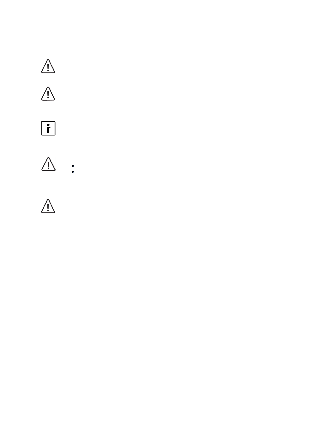
WSL141
1 Refrigerant line - for gas
2 Refrigerant line - for liquids
3 Cold sanitary water
4 Hot sanitary water
5 Return line system
6 Supply pipe system
12
Page 13
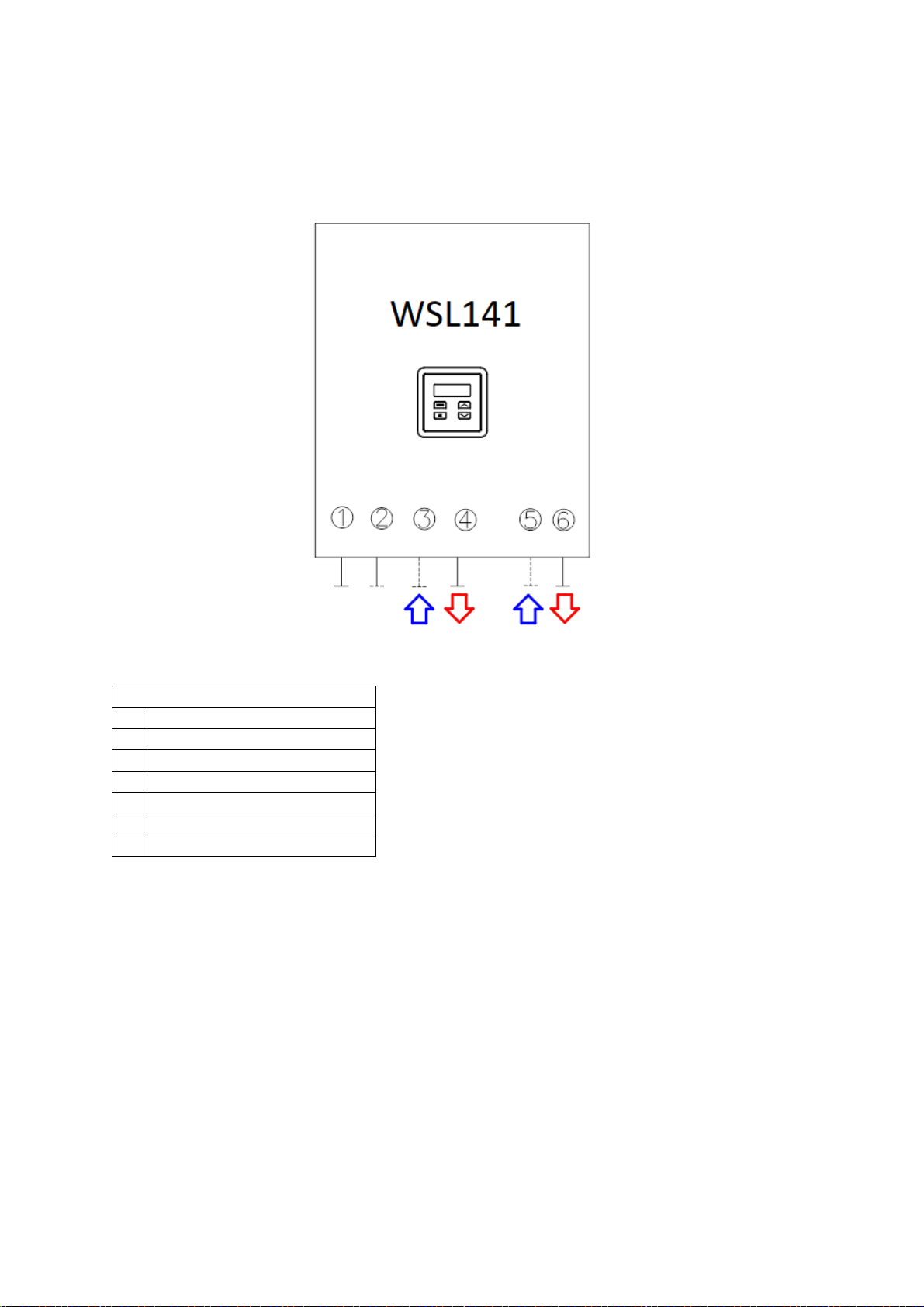
WSL142
1 Refrigerant line - for liquids
2 Refrigerant line - for gas
3 Cold sanitary water
4 Circulation of sanitary water
5 Hot sanitary water
6 Supply pipe system
7 Return line system
13
Page 14
4.2 Location of the device
CAUTION
NOTE
It is obligatory to consider the minimal clearance from obstacles for ensuring unobstructed
access for maintenance and service.
NOTE
The location of the device has to be accessible with manual transport devices to ensure
undisturbed delivery of replacement parts and equipment for maintenance and servicing.
The operator is charged costs connected with hiring special equipment for installing the
device, servicing and maintenance separately, these costs are not subject of the warranty.
NOTE
When you install the device into the building, make sure that you build in a water drain which
will serve as a water drain in case of spillage.
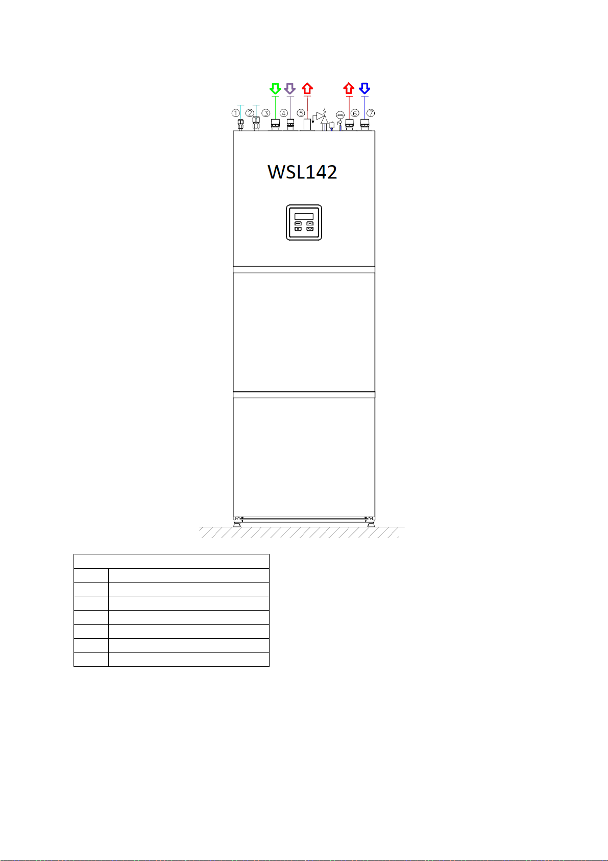
4.2.1 Minimal clearance from the device
The device must not be installed under pipelines because there is a possibility of condensate
forming. Ingress of water condensate can cause disturbances in the operation.
NOTE
The location of the internal device must be dry and in the temperature range between +10 °C
and 40 °C.
Minimal clearances of the external device from walls for seamless operation, maintenance and
servicing.
WSL141 Clearances
14
Page 15
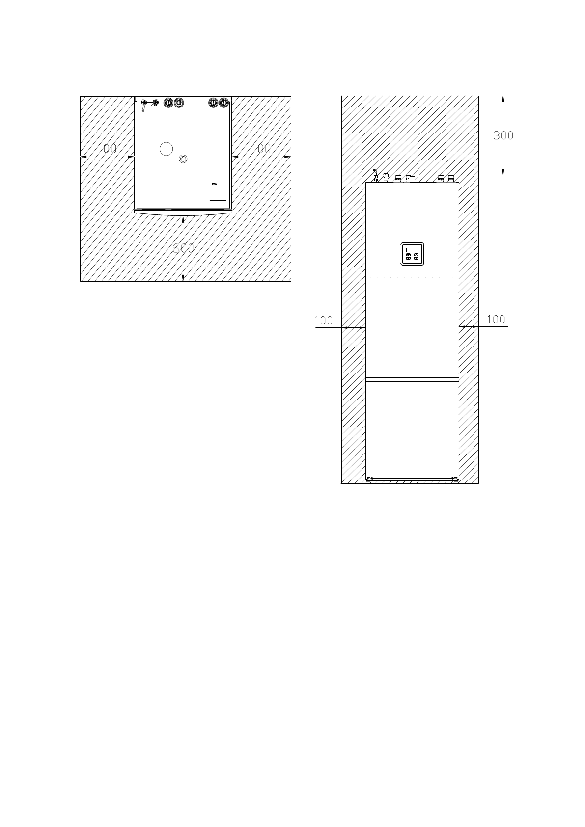
WSL142 Clearances
15
Page 16
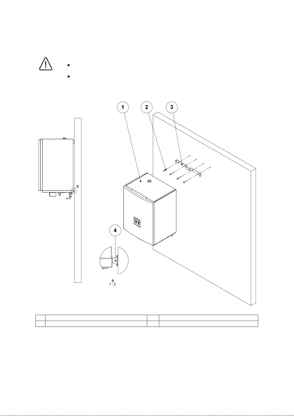
4.2.2 Wall mounting
CAUTION
In the case of WSL141,
The wall and screw fittings must hold the weight of the device. See technical
information.
The device must be levelled
1 Hydro module 3 Wall mount
2 Screws (accessories) 4 Levelling screw
16
Page 17
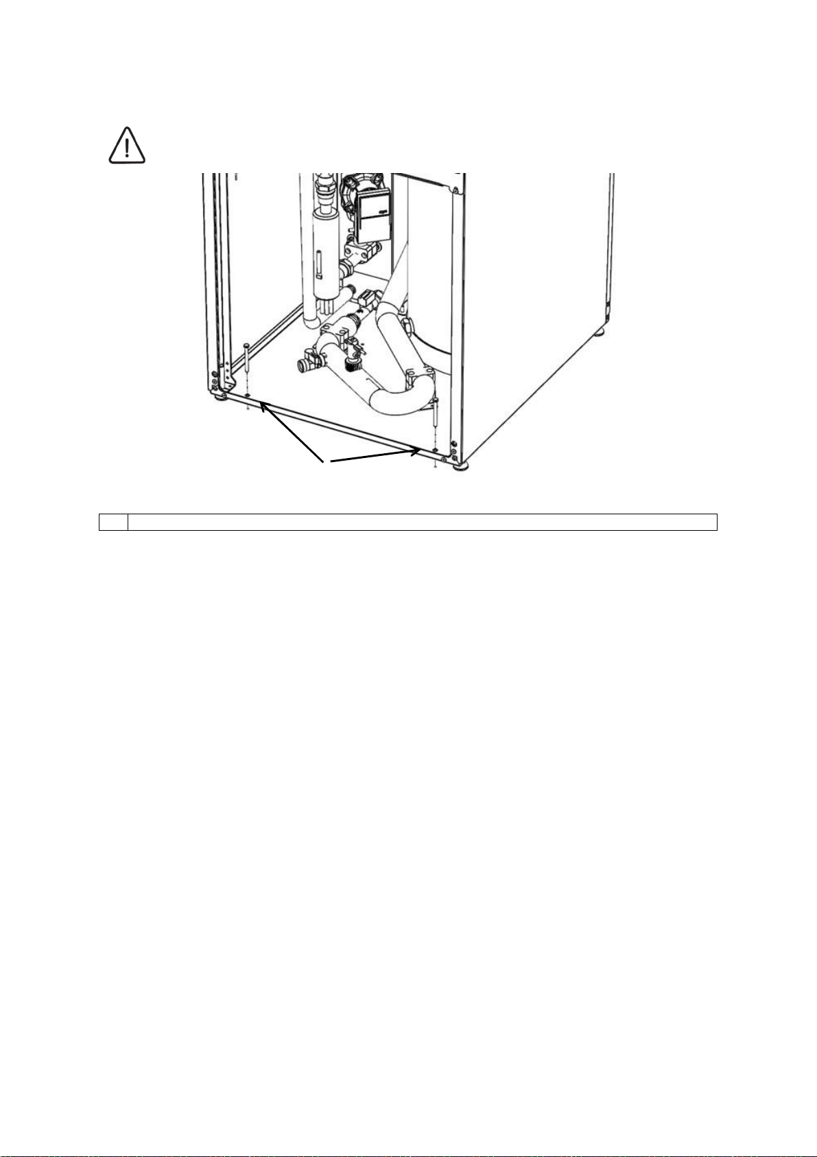
4.2.3 Attachment of the indoor unit
CAUTION
The indoor unit has to be screwed to the base (the screws are not part of the delivery).
1
1 Screws holes ɸ10 for attaching the indoor unit.
17
Page 18
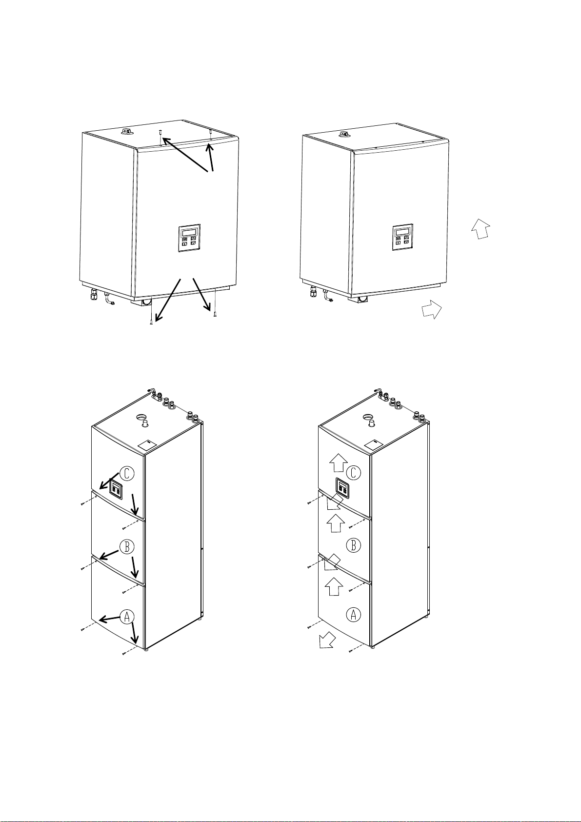
4.2.4 Removal of front cover
1
Removal of side WSL141,
1
Unscrew 4 screws of the (1)
side
Removal of side WSL142,
Open the cover lid towards yourself and push
upward
First unscrew 2 screws of the
lid (A).
Open the lid (A) towards yourself and push
upward. After this repeat the procedure for each
lid.
18
Page 19

4.3 Connection with the external device
The connection between the internal and external device is performed via refrigerant pipes.
CAUTION
The pipeline and electrical cables have to be protected with heat and waterproof insulation
in a protective pipe. This prevents the pipe connections soaking in cases of high
groundwater or rainwater and with it intensive draining of heat into its surroundings.
4.3.1 Refrigeration connection - Gas and liquid connection
The pipe connection between the external and internal device can be made by laying the pipes in two
ways:
A inside two separate ribbed protective pipes,
B in one joint ribbed protective pipe.
A B
P16 Fill with waterproof polyurethane
foam
P17 Protective pipe for external sensors
and communication cable
P18 Copper pipe Cu P22 Ribbed protective pipe min. ɸ 150
P19 Insulation min. 13 mm.
Preparation of the refrigeration pipe
Prepare the refrigeration pipe in steps. Unsuitably made joints are one of the main reasons for leakage,
the joints must thus be made thoroughly and in accordance with the listed steps.
STEP 1: Cutting of the pipe
Use a pipe cutter which does not produce chips to cut the pipe.
Determine the distance between the outdoor and indoor device.
Cut the pipe to appropriate length, and connect the internal and external device.
Make sure that the pipe after soldering / screw driving not be tense.
P20 Ribbed protective pipe min. ɸ 75
P21 The ribbed protective pipe for the power cable
depends on the dimension of the supply cable
19
Page 20

1
3
2
4
1
4
2
5
3
6
7
External diameter
‘'A'' [mm]
[inch]
[mm]
9.52 3/8 1.5 ~ 1.7
15.88
5/8 1.6 ~ 1.8
Copper pipe
Inclined
Uneven
Rough
STEP 2: Removal of chips
Remove all chips from the part where the pipe was cut.
Hold the pipe downward during cleaning so that the chips do not fall into the pipe.
1. Copper pipe
2. Copper pipe held downward
3. Beveler
In the case of WSL141, WSL142
STEP 3: Inserting the screw nut
Remove the screw nut from the pipe in outdoor unit.
Insert the screw nut into the pipe which has been cleaned.
STEP 4: Edging
The edging has to be performed with tools for edging as shown:
Holder
Copper pipe
Fitting
1. Copper pipe
2. Screw nut
Cone
Bracket
Handle
Holder
Mount the copper pipe firmly into the tool for edging. Consider the dimensions listed in the table
below.
20
Page 21

STEP 5: Testing
2
5
7
External diameter
Torque
[mm]
[inch]
[Nm]
Compare the edging of the pipe with the picture below.
In the case of damaged edging, cut the part off and repeat the edging procedure.
1 Circular edging of the pipe of the
same length.
Circularly smooth edge
3 Interior edge and surface without
scratches
Connecting the pipe-refrigerant connection on the interior device
STEP 1: Determine the direction of the pipe connection
Connect the connecting pipes to the device from below (wall unit of HM). In the case of the HM
model with integrated boiler, make the connection from above.
In the case of WSL141 and HM142 S1
STEP 2: Pipe connection
Remove the side (see chapter 4.2.3)
Align the end of the connection pipe with the middle of the pipe from indoor unit and then tighten
the screw nut by hand.
Tighten the screw nut with a torque wrench until it clicks.
Prescribed torques for tightening:
4 Inclined edge
Uneven surface
6 Cracked / rough
Unequal thickness
9.52 3/8 34 – 42
15.88 5/8 65 – 81
21
Page 22

1
2
1
2
2
1
Torque key
1
2
Torque key
Counter key
Counter key
22
Page 23

4.4 Hydraulic connection
CAUTION
WARNING
The design engineer has to check, calculate and determine the correct circulation pumps
type, valves, safety elements and connecting pipes of the heating system.
WARNING
Before connecting the device, it is necessary to rinse the pipe system thoroughly and
remove impurities (solid particles, oils, greases ...).
Use suitable detergents if necessary.
CAUTION
In case of compact HM, the ball valve with exhaust has to be installed on the liquid pipes.
The place of installation has to be on the lowest point between the outdoor and indoor unit.
4.4.1 DHW system
The hydraulic connection has to be installed in accordance with the national and local regulations for
connecting buffer tanks for DHW in force. The room the device is installed in must have a drain on the
floor installed below the level of the device in case of water leakage. The following picture shows the
correct hydraulic connection of the device.
Because different materials are used on the pipe installation, all connections on the device
(cold and hot water, circulation, heat conductor) have to be galvanically isolated; otherwise
corrosion of connections can occur on the inner side of the buffer tank for DHW. We
recommend placing galvanic isolators made of red brass the length of at least twice the
diameter of the pipe on the connections.
CAUTION
The buffer tank for DHW is intended for storing drinking water, this is why the water has to
be in accordance with the national regulations on drinking water in force; otherwise, damage
to the device and a termination of the warranty can arise.
CAUTION
The cold DHW connection of the device must be fitted with a safety valve with the rated
pressure of 0.6 MPa (6 bar).
NOTE
The cold DHW connection must be fitted with an expansion vessel suitable for drinking
water. The selection and installation must be in accordance with the standard DIN 4807 T5.
CAUTION
For proper operation of expansion vessel, a suitable setting of the vessels operating
pressure must be made. The pressure is set in regards to the pressure in the DHW system.
The setting needs to be checked every 12 months.
Setting the pressure for the expansion vessel for DHW
Expansion vessel for DHW is factory filled to a precharge pressure p0 with dry nitrogen. The pressure
must be set depending on the settings of the pressure reducing valve on the DHW supply to the building.
The pressure in the expansion vessel must be set according to the following formula:
0,02 ,
( 0,2)
23
Page 24

p
1
2
3
4
5
6
7
8
9
10
Adjusting the safety valve
[MPa (bar)]
System pressure
[MPa (bar)]
Volume of the DHW [
l]
Expansion vessel
[l]*
– pressure in the expansion vessel
0
p
– setting of the pressure reducing valve
rv
In the case of WSL141,
Ball valve
Pressure reducing valve
Check valve
Safety valve
Expansion vessel
Charging pipe
Circulation pump
Cold sanitary water
Cold circulation water
Warm sanitary water
1
7
1
1
910
5
5
8
4
1
6
3
2 1
3
0,6 (6,0)
0,3 (3,0) 0,35 (3,5) 0,4 (4,0)
200 5 8 12
300 15 19 26
* The actual size of the expansion vessel has to be defined by the installer/design engineer according to the extent of the system
the device will be installed in.
24
Page 25

1
2
3
4
5
6
7
8
9
10
Adjusting the safety valve
[MPa (bar)]
System pressure
[MPa (bar)]
Volume of the DHW [
l]
Expansion vessel
[l]*
In the case of WSL142,
Ball valve
Pressure reducing valve
Check valve
Safety valve
Expansion vessel
Charging pipe
Circulation pump
Cold sanitary water
Cold circulation water
Warm sanitary water
1
7
1
3
1
13
21
4 5
8 9610
0,6 (6,0)
0,3 (3,0) 0,35 (3,5) 0,4 (4,0)
200 5 8 12
* The actual size of the expansion vessel has to be defined by the installer/design engineer according to the extent of the system
the device will be installed in.
DHW tank drain
The drain valve at the bottom of the buffer tank is the most suitable in case the buffer tank for DHW has
to be emptied. Attach a hose to the drain valve and attach its end to the drain.
25
Page 26

Drain valve
26
Page 27

4.4.2 Heating system
For unobstructed and safe operation it is important to have a heat accumulator with a minimal volume
of 40 l (integrated in the ). The accumulator is needed for hydraulic balancing, ensuring unobstructed
flow and defrosting. A larger accumulator ensures a more balanced temperature of heating and more
comfort.
NOTE
When installing an additional larger heat accumulator, it is necessary to close the ball valve
in the indoor unit. The location of the ball valve is indicated on the picture below.
In the case of WSL141,
In the case of WSL142,
C Ball valve
C Ball valve
C
27
Page 28

4.4.3 The scheme of the heating system
Below you can find an example of the basic hydraulic scheme of the heating system for the wall model
of the hydro module and the model with an integrated boiler. For other circuits see The Hydraulic
Circuit Diagram Catalogue.
CAUTION
The supply pipe of each heating cycle must be fitted with an abutment safety thermostat
connected sequentially with the circulation pump to safeguard against the inflow of a
medium of excessive temperature.
ELEMENTS
COMB E,F Connection to various types of heat pumps
TSV Warm sanitary water
HSV Cold sanitary water
BO Boiler for sanitary water
PLC Processing unit
PST Pipe safety thermostat
KT-1
WSL KT-2
TS Connector on PLC
Q1-Q12
A1-A8 Analogue input (input/output module MD1 and MD2)
D1-D9 Digital input (input/output module MD1 and MD2)
MD1 Basic input/output module 1
T1 Thermostat of heating cycle 1
T2 Thermostat of heating cycle 2
OC1 Circulation pump of heating cycle 1
OC2 Circulation pump of heating cycle 2
MV2 Mixing valve of heating cycle 2
OGK-1 Heating cycle 1
OGK-2 Heating cycle 2
MD2 Expansion input/output module 2
T3 Thermostat of heating cycle 3
T4 Thermostat of heating cycle 4
OC3 Circulation pump of heating cycle 3
OC4 Circulation pump of heating cycle 4
MV3 Mixing valve of heating cycle 3
MV4 Mixing valve of heating cycle 4
OGK-3 Heating cycle 3
OGK-4 Heating cycle 4
MARK CHARACTERISTICS MARK CHARACTERISTICS
CONNECTING
TERMINALS
Ball valve
Circulation pump
Ball valve with exhaust
MARK CHARACTERISTICS
Room temperature corrector WSL KT-1(can be used in all
heating cycles)
Room temperature corrector WSL KT-2 (can be used in all
heating cycles)
Digital outputs of regulation ~ 230 V (input/output module MD1
and MD2)
Manometer
Temperature sensor
Thermometer
Drain valve with plug
Cleaning piece
Expansion vessel
Safety valve
Non-return valve
Magnetic separator of impurities
Consumer of heat / coolness
Automatic vent
3-way switching valve with EM drive
3-way mixing valve with EM drive
Supply pipe
Return line
28
Page 29

Pipe safety thermostat
CONNECTING
TERMINAL
S
HM
Hydro module
1
Refrigerant
(freon) line
- gas SPLIT m
odel
1
Return line
(COMPACT model)
2
Refrigerant
(freon) line
- liquid SPLIT model
2
Supply pipe
(COMPACT model)
3
4
Supply pipe h
ot sanitary water
5
Return line system (applies to the heating regime)
6
Supply pipe system (applies to the heating
regime)
Legend of reading:
OC1
MD1:Q7
The scheme of the heating system of the wall model of the interior device.
The elements on the scheme are marked in the following
manner:
Mark of the element
Mark of the connecting terminal on
the input/output module - MD
Mark of the input/output module
ELEMENTS
MARK CHARACTERISTICS
Return line cold sanitary water
29
Page 30

Scheme of the heating system in hydro modules with an integrated boiler
Legend of reading:
OC1
The elements on the scheme are marked in the following manner:
Mark of the element
MD1:Q7
Mark of the connecting terminal on
the input/output module - MD
Mark of the input/output module
ELEMENTS
HM Hydro module with integrated boiler
6 Return line system (applies to the heating regime)
7 Supply pipe system (applies to the heating regime)
CONNECTING
TERMINALS
MARK CHARACTERISTICS
30
Page 31

4.4.4 Charging of the heating system
CAUTION
WARNING
Thorough venting of the system has to be ensured. Otherwise, malfunctions in operation
may occur.
CAUTION
An expansion vessel of suitable dimensions must be fitted to the heating system. The
expansion vessel must be dimensioned in accordance with standard EN 12828.
CAUTION
For normal operation of the expansion vessel, it is necessary to perform proper adjustments
of the tank’s working pressure. The settings have to be checked every 12 months.
The pressure settings of the expansion vessel and filling the hating system
A - Filling the system.
B - Expansion vessel.
C - Ball valve with exhaust.
D - Air filling valve.
H - Height of the heating system.
psv - Pressure of the safety valve.
Consider the maximal operational pressure of the vessel.
NOTE
Unsuitable pre-load of the expansion vessel with the pressure p0 is the reason for incorrect
operation of the heating system.
NOTE
The dimensions of the expansion vessel must be in accordance with standard EN 12828.
31
Page 32

Setting the pressure for the expansion vessel p0
Before filling the system with water, check and set the pressure p0.The expansion vessel is
factory set to the pressure specified on the standard label. For correct operation of the system,
set the pressure p0 according to the equation below. The filling must not exceed the maximal
operational pressure specified on the serial label of the expansion vessel.
Calculate the p0 pressure value with the help of the equation:
bar=
+0,02[MPa],
+0,2[bar]).
(
MPa=
CAUTION
If the calculation shows a pressure lower than 0,1 MPa (1 bar), set the pressure of the
expansion vessel to 0,1 MPa (1 bar).
P0 [MPa (Bar)] – pressure in the expansion vessel,
p
p
[MPa (Bar)] – minimal allowed pressure of the heating system,
0min
[MPa (Bar)] – maximal allowed pressure of the heating system,
0max
H [m] – Height of the heating system.
Set the amount of pressure in the expansion vessel by releasing or supplementing dry nitrogen.
Record the new value of the pressure p0 on the serial label.
Open the ball valveof the expansion vessel carefully, open the vents and close the drain.
Filling the heating system
Use the filling valve to fill the system with water of suitable quality (with anti-corrosion additives,
etc.) to the pressure pF.
Filling the system to the final pressure
MPa=
(
bar=
MPa+0,03[MPa],
bar+0,3bar)
The final pressure of the system is determined by heating the system to the maximal heating
temperature (thermal degassing).
Turn off the circulation pumps, open the vents and vent the system.
Fill the system up to the final pressure which is 0,05 MPa (0,5 bar) lower than the venting
pressure of the safety valve.
MPa≤
(
bar≤
MPa−0,05[MPa],
bar−0,5[bar])
p
– the final pressure of the system,
E
p
– the pressure of the safety valve.
SV
32
Page 33

4.4.5 Preparing the heating hydraulic system - secondary
TYPE OF PRESENT
SUBSTANCE
INFLUENCE TO THE HEAT
CONDUCTOR
Organic sediment
mg / L
0
> 20
-
> 300
+ 0
Allowed water hardness
°dH
5 – 10
> 500
-
> 0.2
+ 0
> 20
-
> 0.1
+ 0
> 100
+ 0
> 2
+ 0
> 0.05
+ -
> 300
0
> 0.2
+ 0
> 300
-
Sulphite (SO
) mg / L
< 1 +
> 5
-
Prepare the system according to one of the recommended hydraulic schemes (Catalogue of Hydraulic
Wiring Diagrams) which is specified by the manufacturer of the device. This is the only way to ensure
reliable and effective operation of the device. After connecting the device to the heating system, it is
necessary to examine all circulating pumps and electric motor valves if they function correctly.
The device must be connected to the heating system via rubber compensator or flexible pipes. The
latter must not be under tension in final position, this would decrease the devices noise and vibration
protection. In extreme cases this can also lead to damage to the device.
Quality of heating water
Maximal allowed content of individual substances in the heating water and the influence of these on the
heat exchanger are presented in the table below. It is not allowed to use heating water which contains
any substance in concentrations which cause corrosion in the heating system (influence “-”). It is also
not allowed to use heating water which contains two or more substances in concentrations which could
cause corrosion in the heating system (influence “0”).
UNIT CONCENTRATION
Ammonia NH3 mg / L
Chloride mg / L
Electrical conductivity µS / cm
Iron (Fe) removed mg / L
Free carbonic acid mg / L
Manganese (Mn) removed mg / L
Nitrates (NO3) removed mg / L
pH value mg / L
Oxygen mg / L
Hydrogen sulphide (H2S) mg / L
HCO3- / SO
Hydrogen carbonate mg / L
2
- mg / L
4
< 2
1 to 20
< 300
< 10
10 to 500
< 0.2
< 5
5 to 20
< 0.1
< 100
< 7.5
7.5 to 9
> 9
< 2
< 0.05
> 1
< 1
< 70
70 to 300
+
0
0
+
+
0
0
+
0
+
0
0
+
Aluminium (Al) removed mg / L
Sulphates mg / L
Chlorine (gas) (Cl2) mg / L
< 0.2
< 70
70 to 300
3
< 1
1 to 5
+
0
+
0
33
Page 34

Table: Influence of various aggressive substances in the heating water on the stability of stainless
CAUTION
WARNING
copper welded plate transmitters. (+ = no influence, 0 = danger of corrosion, - = corrosion - use not
permitted).
CAUTION
The heating system has to be filled with water with the hardness between 5 °dH and 10
°dH. Malfunctions of the device because of water hardness are not covered by the warranty.
The quality of the water used in the heating system is very important. The water from the water supply
is mostly not suitable for use in the heating system. To ensure adequate water hardness you must built
the water softener into the system.
The heating systems must not be filled with dirty or corrosive water. The heating water must be prepared
by adding anti-corrosion and anti-biological agents as well as agents against algae.
The water used for heating DHW via the built-in heat exchanger in the buffer tank for DHW
has to be in accordance with the requirements of standard VDI 2035 and must not contain
microorganisms. The heating system has to be filled with soft water which has been added
anti-corrosion and antibacterial agents for preventing corrosion. Before filling the heating
system has to be cleaned of all impurities.
The heating system has to be thoroughly vented. You must prevent air, including diffusion
air entering the device.
NOTE
To prevent damage to the components of the hydraulic system, we recommend the
additional installation of SpiroVent RV2 air (micro-bubble) venting system.
The presence of micro bubbles in the system eventually forms larger bubbles which in time
can cause corrosion of the system, system component malfunction and operation
disturbance.
In new systems, the impurities are a consequence of welding, soldering, dirty pipes (oil, grease), etc.
In case the impurities start accumulating in the device this can worsen the flow and heat transfer, in
worst cases also freezing of water in the heat exchanger and consequently the destruction of the device.
WARNING
To protect the device from intake and accumulation of dirt in the heat exchanger you must
install the strainer on the return line, before entry into the device.
A galvanic disconnection between individual elements of the heating system (i.e. boiler,
container ...) is obligatory.
In the case of using grey steel pipes in the heating system, it is necessary to degrease them (the interior
of the pipe) before connecting them to the heat pump.
34
Page 35

4.5 Electrical connection
CAUTION
Connect the external device to the mains according to the instructions described in this chapter.
CAUTION
Connecting the device to the electrical network has to be performed in accordance with the
standards for connecting devices into the electrical network. The device has to be connected
to the electrical network via the power supply cut-off which is installed into the electrical
installation under the regulations in force.
DANGER
The final electrical connection can only be performed by the person authorised by the
manufacturer to ensure the correct and efficient operation of the device.
IT IS STRICTLY PROHIBITED FOR UNAUTHORISED PERSONS TO TAMPER WITH
THE ELECTRICAL CONNECTION OF THE DEVICE.
DANGER
The device must be connected to the mains, which has a built-in RCD
switch type A.
CAUTION
The device must be connected to the mains with a cable with an appropriate diameter. The
electrician defines the diameter of the cable according to the installation method, distance
of the device from the main electrical cabinet and the power of the device.
residual-current devic,
The cable must be routed through the cord anchorage installed before the connecting
terminals in the indoor unit. Make sure the cable connected in the indoor unit is relieved from
strain.
CAUTION
The total electrical power of the devices which are directly connected to the regulation must
not exceed 500 W. Otherwise it is necessary to ensure separate power to the external
devices and to connect only the control elements to the regulation.
WARNING
Pay attention to the characteristics of the inputs and outputs. Incorrect connection can lead
to damage to the device.
CAUTION
You can not put the communication cable (in accordance with good engineering practices
and regulations) together with power cables.
4.5.1 Removal of the control unit lid
See chapter 4.2.3.
35
Page 36

4.5.2 Description of elements in electrical closet
In the case of WSL141
X4
GND
D 8
GND
D 7
GND
X7
A +
B -
GND
TT3003
12 V
X6
A +
B GND
12 V
X5
BUS-A
BUS-B
GND
10V
D 6
GND
D 5
X3
A 7
GND
N
Q10-
Q9+
N
Q8
N
Q7
X2
A 2
GND
A 5
GND
N
Q12
N
Q11
X1
L3
/
/
L2
L1
L1
N
N
1 Input/output module MD1 7 Communication with the external WPLV
device
2 Power supply ~ 230 V / 12 V 8 Connecting terminals room temperature
corrector KT-1(2)
3 RESET button (Thermal protection of the
electrical heater).
9 Place of grounding the plated (braided)
communication cable
4 Connecting terminals of external devices 10 Communication with the external WPL
device and internal expansion unit
TT3003.
5 Connecting terminals of the power line 11 Connecting terminals neutral conductor
6 WEB module 12 Electrical contactor
36
Page 37

In the case of WSL142
GND
D 8
GND
D 7
GND
D 6
GND
D 5
A 7
GND
N
Q10Q9+
N
Q8
N
Q7
A 2
GND
A 5
GND
N
Q12
N
Q11
A +
B -
GND
12 V
A +
B GND
12 V
BUS-A
BUS-B
GND
L3
L2
L1
N
1 Input/output module MD1 7 Communication with the external WPLV
device
2 Power supply ~ 230 V / 12 V 8 Connecting terminals room temperature
corrector KT-1(2)
3 RESET button (Thermal protection of the
electrical heater).
9 Place of grounding the plated (braided)
communication cable
4 Connecting terminals of external devices 10 Communication with the external WPL
device and internal expansion unit
TT3003.
5 Connecting terminals of the power line 11 Connecting terminals neutral conductor
6 WEB module 12 Electrical contactor
Display - process module
37
Page 38

1 Process module PLC 5 WM - connection with the WEB module
(factory made).
2 TE2 - connection with the input/output
module (factory made).
3 TS - connection of the room corrector KT-
1(2)
4 TEX - MODBUS communication with the control system of the building (BMS). In case of an
external WPLV device, communication with module Gateway PI485.
6 RQ2 - connection for resetting the alarm
(factory made).
7 RQ1 - connection of the signal for reporting
an alarm (optional).
4.5.3 Schematic display of the control system - TT3000
CAUTION
Connect the internal control unit TT3000 with the external device with a plated cable the
plating (braiding) of which has to be grounded on the envisioned spot ( –functional
earthing).
In the case of WSL141 and HM142
Proper functioning requires a connection between the terminal terminal X5 on the internal unit and
connecting terminals Bus_A [+] / Bus_B [-] / GND and +10 V on the Gateway PI485 module on the
external device.
38
Page 39

ELEMENTS
MARK
A Room corrector KT-1(2)
KT-1 Room temperature corrector WSL KT-1(optional)
A +, B- Communication
GND, 12 V Power supply
WSL KT-2 Room temperature corrector WSL KT-2 (optional)
A +, B- Communication
GND, 12 V Power supply
B Internal control unit TT3000
3 Basic input/output module MD1
TE1 Communication with I/O module MD3 and/or MD2
TE2 Communication with the control electronics of the PLC screen module
JMP Set-up of bridges (without)
X7 Connecting terminal for communication with MD3 module and/or expansion
A +, B- Communication
GND, 12 V Power supply
X6 Connecting terminal for the spatial correctors(optional)
A +, B- Communication
GND, 12 V Power supply
X5 Connecting terminal for communication with external modul Gateway PI485
BUS-A, BUS-B Communication
GND, +10 V Power supply
5 Web module
TW MODBUS Communication with PLC
TX MODUBUS Not in use
Ethernet Internet (Ethernet) connection
PLC Process module
WM Communication with Web module
TEX MODBUS communication with the control system of the building (BMS). In case
TS Communication with the room temperature corrector
TE2 Communication with the basic I/O module MD1
D Expansion wall unit TT3000
3b Expansion input/output module MD2
TE1 Communication with the basic I/O module MD1
TE2 Not in use
JMP Set-up of bridges (in first position)
X7 Connecting terminal for communication with I/O module MD1
A +, B- Communication
GND, 12 V Power supply
C External input/output module MD3 in the WPL device, Gateway PI485 in the
3c External input/output module MD3 in the WPL device
TE1 Communication with the basic I/O module MD1
TE2 Not in use
JMP Set-up of bridge (in second position)
PI485 External module Gateway PI485 in the WPLV device
BUS–A , BUS–B Communication with the control electronics of the PLC screen module
GND Power supply
+ 10 V Power supply
CONNECTING
TERMINALS
CHARACTERISTICS
module MD2
in WPLV device
of an external WPLV device, communication with module Gateway PI485.
WPLV device
39
Page 40

A
KT - 1
A+
B-
GND
+12V
KT - 2
A+
B-
GND
+12V
B
12 V
D
TE1 TE2
GND
TERMOTRONIC
12 V
GND
B -
MD1
JMP
3
A +
X6
C
B A
5
X7
BUS-B
X5
BUS-A
TT3003
PLC
A +
B -
TE2
TS
TEX
WM
GND
12 V
A +
B -
JMP
TE1 TE2
3b
10V
MD2
GND
X7
C
PI485
+ 10V
TE1
TE2
JMP
MD3
3c
GND
BUS-A
BUS-B
40
Page 41

4.5.4 Connecting the internal control unit – TT3000
DANGER
Connecting the device to the power source can only be performed by a qualified installer in
a voltage-free state!
As part of connecting the internal control unit to the connecting terminals X1…X7, connect the
following cables:
Power cable,
Communication cable for the external device,
Temperature sensor of external temperature (only in the case of the external device
WSLHP7and WSLHP11 S1),
Legend of cable connections to the connecting terminals:
MARK CONNECTING
X1
X2
X3
X4
D6, GND 2 x 0.75 mm2 Thermostat of mixing cycle 1 (optional)
D5, GND 2 x 0.75 mm2 Remote on/off (optional)
X5 BUS – A, BUS – B,
X6 A+, B-, 12 V, GND 4 x 0.75 mm2 Communication spatial corrector (optional)
X7 A+, B-, 12 V, GND 4 x 0.75 mm2 Communication of the external control unit in the WPL device and/or internal
5 UTP Web modul
TW MODBUS UTP Communication with PLC
TX MODBUS / Not in use
Ethernet UTP Internet connection
TERMINALS
L1, L2, L3, N,
A5, GND 2 x 0.75 mm2 Temperature sensor of external temperature (only connected in the case of
A2, GND 3 x 0.75 mm2 Temperature sensor for sanitary water (connected only in the case of
Q12, N,
Q11, N,
Q7, N,
Q8, N,
Q10-, Q9+, N 3 x 0.75 mm2 Mixing valve of heating cycle 2 (optional)
A7, GND 2 x 0.75 mm2 Temperature sensor of mixing-heating cycle 2 (optional)
D8, GND 2 x 0.75 mm2 Switch for heating/cooling (optional)
D7, GND 2 x 0.75 mm2 Thermostat of mixing cycle 2 (optional)
GND, +10 V
DIMENSIONS
OF CABLE
Power cable
2 x 0.75 mm2 Additional external source
3 x 0.75 mm2 Cooling valve
3 x 0.75 mm2 Circulation pump of heating cycle 1 (optional)
3 x 0.75 mm2 Circulation pump of heating cycle 2 (optional)
4 x 0.75 mm2 Communication of the external control unit in the WPLV device
CHARACTERISTICS
the device WSLHP7and WSLHP11 S1),
WSL141, WSL-131-1, WSL-131-11 )
expansion unit TT3003
41
Page 42

WSL141, WSL142,
GND
D 8
GND
L1
D 7
GND
D 6
GND
D 5
A 7
GND
N
Q10-
Q9+
N
Q8
N
Q7
A 2
GND
A 5
GND
N
Q12
N
Q11
/
L3
/
L2
L1
N
N
5
TX
TW
Ethernet
N
N
N
N
NN
X7
A +
B -
GND
TT3 003
12 V
X6
A +
B -
GND
12 V
X5
BUS-A
BUS-B
GND
10V
X4
5
TW
X3
TX
Ethernet
X2
X4
X1
X3
X2
GND
D 8
GND
D 7
GND
D 6
GND
D 5
A 7
GND
Q10-
Q9+
Q8
Q7
A 2
GND
A 5
GND
N
Q12
X7
A +
B -
GND
TT3003
12 V
X6
X1
X5
A +
B -
GND
12 V
BUS-A
BUS-B
GND
10V
N
N
N
L3
L2
L1
N
N
Q11
42
Page 43

4.5.5 Cable routing
Glands
In order to ensure tightness of the cable routing follow the below instructions:
1. Make a small hole in the thin rubber membrane for each cable.
2. Push the cable through making sure the membrane isn’t damaged and that the membrane
tightly wraps the cable.
3. Pull the cable back for approximately 5 mm to make a positive seal.
In the case of WSL141,
CAUTION
Make sure that all the cables are fed through the cable glands at the bottom of the unit. In
that way you will ensure the tightness of the device.
In the case of WSL142,
CAUTION
Make sure that all the cables are fed through the cable glands at the top of the unit. In that
way you will ensure the tightness of the device.
Cable glands for
18 cables in total.
43
Page 44

4.5.6 Connection of power cable
CAUTION
A B ~ 230 V / 50 Hz
DANGER
Connecting the device to the power source can only be performed by a qualified installer in
a voltage-free state!
CAUTION
The supply and communication cables have to be laid into the device and electrical cabinet
through separate cable glands and cord anchorage, which are installed before the cable
terminals. This way we ensure the cable is relieved from strain and the electrical cabinet is
protected from water penetration.
CAUTION
Wrong dimensioning of the power cable or too weak terminal fuses of the device could lead
to an overload of the safety elements on the power grid of the building which could lead to
overheating of the electrical installation. Follow the requirements listed in this manual.
In case of connecting the multi-wire flexible cable to the connecting terminal, it always has
to have an end sleeve at the end.
1 End sleeve 2 Multi-wire flexible cable
3 Massive single-wire cable
To connect to connecting terminals of the device, use cables with crimped end sleeves or a
massive single-wire cable.
The dimensions of the power cables are listed in the chapter under technical information Error!
Reference source not found..
The device comes with an electrical heater 3 x 2 kW. The power supply is connected according to your
needs:
a) ~ 230 V / 50 Hz on the connecting terminals L1, N and PE,
Connecting terminals of the supply cable
For connecting the 2 kW heater,
X1
3N ~ 400 V ~ 230 V ~ 230 V
L3
L2
/
2 kW
16 A
/
4 kW
20 A
L1NL1
N
connect the connecting terminals in
section A to L1, N and PE ( ).
Input fuse: 16 A.
For connecting the 4 kW heater,
connect the connecting terminals in
section B to L1, N and PE ( ). It
is also necessary to connect the
bridge from L1 to /.
Input fuse: 20 A.
Terminal PE ( ) (yellow-green cable), terminal N (blue cable), terminals L1 (black or grey or brown
cable).
44
Page 45

b) 3N ~ 400V / 50 Hz on the connecting terminals L1, L2, L3, N and PE ( ).
X5
Connecting terminals of the supply cable
X1
L3
L2
/
/
L1NL1
N
4.5.7 Connecting terminals of the communication cable
The communication cable is intended for the communication between the control unit TT3000 and
external device. For the dimensions of the communication cable, see technical data Error! Reference
source not found.
Terminals L1, L2, L3 (3 x black or
black, grey, brown cable)
Terminal N (blue cable)
Terminal PE ( ) (yellow-green cable)
Input fuse: 3x16A
CAUTION
It is important to correctly connect the connecting terminals X5 and X7.
In the case of WSL141 and WSL142
The communication cable connects the external device to the terminal terminal X5 on the internal
device. It is necessary to connect the terminals BUS–A, BUS–B, GND and 10 V.
BUS-A
BUS-B
GND
10 V
DANGER
The communication connection is considered as a low-voltage connection. The type of the
communication cable must be H05VV-F 4 x 0.75mm2 (IEC 60227-53) or similar.
In the case of a prefabricated FTP cable, connect cable 1, 2 to BUS – A, 2, 3 to BUS – B and GND to
7, 8.
45
Page 46

4.5.8 Ethernet connecting terminal
Use an Ethernet connection terminal to connect your device to the Home.Cloud application. Use the
communication cable to connect the "Ethernet" connector to the network router and activate it. To
register the device in the Home.Cloud, see the instructions Instructions for connecting the device to
the cloud.
NOTE
Use the RJ-45 gold-plated connector and crimp it with a certified tool on the 5e UTP
Place of Ethernet terminal
In case of WSL141
cable. The connection between the connector and the router must be made according
to T 568 - A standard.
1 Ethernet terminal
1
46
Page 47

4.5.9 Electrical scheme
WEB MODULE - OPTIONAL
Ethernet
Internet
Ethernet
X3
A7
GND
N
Q10Q9+
2.
N
Q8
1.
N
Q7
X2
A2
GND
A5
GND
Q12
N
Q11
X1
L3
L2
L1
L1
N
N
8.... ....1
8 76 5 43 2 1
TW
MODBUS
87 6 5 43 2 1
TX
....18....
MODBUS
X4
GND
D8
10
°C
GND
0
20
1
30
D7
GND
10
°C
0
20
1
30
D6
GND
D5
A2
NOT FOR:
HM 131 K1/HK 3F
HM 131 S1/HK UF X1
HM 141 S1/HK UF X1
RQ1
RQ2
WM
PLC
TE2TS
TEX
GND
~230V ~230V ~230V
SK Q10 Q11 Q12
12V
D1 D2 D3 D4 D5 D6 D7 D8 12V
N
~230V ~230V ~230V
SK Q7 Q8 Q9
~230V ~230V ~230V
SK Q4 Q5 Q6
A8
GND
5V 5V
A7
A6
GND
A5
MD1 (MBIO12)
5V 5V
A4
GND
A3
5V 5V
A2
GND
5V 5V
A1
JMP
TE2
~230V ~230V ~230V
SK Q1 Q2 Q3
TE1
Q13
PWM +
12V
PWM -
A1 A6
A3 A4
X6
A+
B-
KT.
GND
12V
KON2
+A+B-
GND
X5
BUS-A
BUS-B
GND
10V
X7
A+
BGND
12V
D4
NOT FOR:
HM 131 K1/HK 3F
HM 132 K1/HK UF X1
47
Page 48

ELEMENT CONNECTING
X1 Power cable
WPLV X5 Communication with the external control unit in the WPLV device
BUS - A
BUS - B
GND
/
WPL X7 Communication with the external control unit in the WPL device and/or internal
A+ , B-
12 V, GND
X2 Temperature sensor for external temperature
A5, GND It is connected only in the case of the device WSLHP7 and WSLHP11
X2 Temperature sensor of sanitary water
A2, GND Connected only in the case of WSL141,
X2 Cooling valve
Q11, N
X2 Additional external source
Q12, N, PE
X3 Circulation pump of heating cycle 1 (optional)
Q7, N, PE
X3 Circulation pump of heating cycle 2 (optional)
Q8, N, PE
X3 Mixing valve of heating cycle 2 (optional)
N, Q9+, Q10-
X3 Temperature sensor of mixing-heating cycle 2 (optional)
A7, GND
X4 Switch heating/cooling and/or PV signal (optional)
D8, GND
X4 Thermostat of mixing cycle 2 (optional)
D7, GND
X4 Thermostat of mixing cycle 1 (optional)
D6, GND
X4 Remote on/off (optional)
D5, GND
X6 Communication room temperature corrector (optional)
A+, B-, 12 V,
5 Web module
A Communication with PLC
B Not in use
C Internet connection
3 MD1 Basic input/output module MD1
PS D4 Flow switch
M 4.1 Q4 Switching valve for sanitary water
M3 Q3 Main circulation pump
S1 A1 Temperature sensor of the return line
S3 A3 Temperature sensor of the entry of the refrigerant into the condenser
S4 A4 Temperature sensor of the exit of the refrigerant from the condenser
S6 A6 Temperature sensor of the supply pipe
10 Power supply ~ 230 V / 12 V
PLC Process module
WM Communication with the Web module
TEX MODBUS communication with the control system of the building (BMS)
TS Communication with the room corrector
TE2 Communication with the basic module MD1
RQ1 ALARM dry contact
RQ2 RESET dry contact
1
C Electrical contactor of the electrical heater
EG Flow electrical heater
TV Thermal protection of the electrical heater
TERMINALS
L1, L2, L3, N,
GND
MARK CHARACTERISTICS
expansion wall unit TT3003
48
Page 49

ELEMENT TERMINAL
BLOCK
X1 L1, L2, L3, N, PE Power cable
X2 A5, GND Temperature sensor for external temperature. It is connected only in the case of the
Q11, N Cooling valve
Q12, N, PE Additional external source
X3 Q7, N, PE Circulation pump of heating cycle 1 (optional)
Q8, N, PE Circulation pump of heating cycle 2 (optional)
N, Q9+, Q10- Mixing valve of heating cycle 2 (optional)
A7, GND Temperature sensor of mixing-heating cycle 2 (optional)
X4 D8, GND Switch heating/cooling and/or PV signal (optional)
D7, GND Thermostat of heating cycle 2 (optional)
D6, GND Thermostat of heating cycle 1 (optional)
D5, GND Remote on/off (optional)
X5 BUS-A, BUS-B,
GND, +10V
X6 A+, B-, 12 V, GND Communication spatial corrector (optional)
X7 A+, B-, 12 V, GND Communication with expansion unit TT3003
1 Flow electrical heater.
2 Three way valve for switching between heating and DHW
3 Basic input/output module MD1
4 D4 Flow switch
5 Web module (OPTIONAL)
TW Modbus Communication with PLC
TX Modbus Not in use
Ethernet Internet connection
6 A6 Temperature sensor of the supply pipe
7 Q3 Main circulation pump
8 A1 Temperature sensor of the return line
9 Process module - PLC
WM Communication with the Web module
TEX MODBUS communication with the ODU.
TS Communication with the spatial corrector
TE2 Communication with the basic module MD1
RQ1 ALARM dry contact
RQ2 RESET dry contact
10 Power supply ~ 230 V / 12 V
L Phase 230 V; 50 Hz
N Neutral 230 V; 50 Hz
V- GND
V+ 12 V dc
11 A3 Temperature sensor refrigerant pipe – condenser inlet. It is connected only in the
12 A4 Temperature sensor refrigerant pipe – condenser outlet. It is connected only in the
13 Membrane Keyboard
14 A2 Temperature sensor of sanitary water. Connected only in the case of WSL141,
C Electrical contactor of the electrical heater
TV Thermal protection of the electrical heater
RC RC Filter.
DESCRIPTION
device WSLHP7 and WSLHP11
Communication with the ODU
Protective earth
case of the device WSLHP7and WSLHP11)
case of the device WSLHP7and WSLHP11)
49
Page 50

4.6 Connection of the spatial corrector WSL KT-1and WSL KT-2
Room temperature corrector WSL KT-1(2) is connected according to the circuit diagram below. It is
necessary to ensure the correct connection of the plated cable to the connecting terminal X6.
RQ1
RQ2
WM
TEX
X6
A +
B -
12 V
GND
TS
C14
PLC
TE2
*
KT - 1
A+ B- GND +12V
KT - 1
A+ B- GND +12V
KT - 1
A+B-GND +12V
S
KT - 1
P
A+B-GND +12V
KT - 1
A+ B- GND +12V
KT - 1
A+ B- GND +12V
KT - 1
A+ B- GND +12V
KT - 1
A+ B- GND +12V
ELEMENTS CONNECTING
TERMINALS
KT-1(2) Room temperature corrector KT-1(2) (optional)
A +, B- Communication
+ 12 V, GND Power supply
PLC Process module
RQ1 ALARM dry contact
RQ2 RESET dry contact
WM Communication with web module
TEX MODBUS communication with the control system of the building (BMS)
TS Communication with the room corrector
TE2 Communication with the basic module MD1
X6 Connecting terminal of the spatial corrector
C14 Plated cable
* Choice of connecting a parallel or a serial connection on X6
P Parallel connection
S Serial connection
MARK CHARACTERISTICS
Grounding of the plated cable (Functional earthing)
or outdoor unit PI485 Gateway
50
Page 51

5. Commissioning of the device
CAUTION
Before the commission it is necessary all the required tasks and inspections from the tasks
for commission.
After professional installation, the authorised contractor has to perform the commissioning of the device.
CAUTION
The commission can only be performed by a person authorised by the manufacturer! If the
commission is performed by an unauthorised person, the warranty is not recognised.
Management of the device must be performed in accordance with current instructions for use.
6. Care and maintenance
The device must be visually inspected once a year. The electrical and hardware installation of the device
have to be inspected. In the case of detected irregularities, contact the authorised technician.
CAUTION
The servicing and maintenance of the device can only be performed by a person authorised
by the manufacturer. In case of a malfunction, first contact the installer who installed the
device.
6.1 Cleaning the water filter
NOTE
Cleaning of water filters on the return into the device is advised to be performed at least
once yearly.
CAUTION
A blocked water purifying component and magnetic filter can lead to a malfunction of the
device or incorrect functioning of the device. In case the display displays a warning of flow
malfunction (”Caution, flow!”).
6.2 Monitoring the pressure in the heating system
NOTE
Periodically, once yearly, check the water temperature in the heating system.
NOTE
In case the pressure falls (i.e. Leakage of the system) the display displays a warning of flow
malfunction (”Caution, flow!”).
6.3 Cleaning of the heat conductors
6.3.1 Cleaning of the heating system (water section)
Residue of grease and sealants in pipes can pollute the condenser of the device up to a point where
cleaning is necessary. In this case the authorised person should perform the cleaning with a solution
(up to 5 % of phosphorous acid) which should be heated to room temperature. The condenser has to
be completely disconnected from the heating system and rinsed with diluted phosphorous acid in the
opposite direction of normal flow.
After cleaning, the condenser has to be rinsed thoroughly with an agent neutralising the acid detergent
so as to prevent the contamination of the heating system.
51
Page 52

WARNING
Acid detergents should be used carefully, instructions of the manufacturer and
environmental regulations must be followed. The cleaning can only be performed by a
qualified person.
If any doubts about using the detergents arise, consult with the manufacturer of the detergent.
6.4 Disturbances in the operation
In case of a malfunction during the operation of the device the display of the internal unit
TERMOTRONIC displays “Caution, malfunction”.
Find the malfunction in the manual. For error correction, call the installer who performed the installation
of the device.
6.4.1 Reset of the thermal protection of the electrical heater
The thermal protection of the electrical heater is an additional safeguard protecting the device in the
following cases:
The electrical contactor which turns on the electrical flow heater can be permanently short-
circuited.
At commission, air is in the system; this causes heating without heat extraction.
The easiest way to determine whether the thermal protection of the electrical heater is turned off is to
turn on the operation of the auxiliary source on the TERMOTRONIC control unit. Determine if you can
feel by hand the difference between the supply line and the return line. The electrical heater works if
the supply line is warmer. How to activate the auxiliary source is explained in the manual.
In case the electrical heater does not work because of one of the aforementioned reasons, the safety
has to be reset after the problem is resolved. You do this by pressing the RESET button shown on the
scheme.
In the case of WSL141
52
Page 53

In the case of WSL142
Thermal protection
Reset the safety thermostat by pressing the red button until you hear a “CLICK”.
NOTE
Resetting the device can only be performed by installers, authorised contractors for
commission or authorised maintenance worker in a voltage-free state.
53
Page 54

7. Technical data
7.1 Dimensions of the device
7.1.1 WSL141,
WSL 141
1 Refrigerant line - for gas
2 Refrigerant line - for liquids
3 Cold sanitary water
4 Hot sanitary water
5 Return line system
6
Supply pipe system
7 Safety valve
8 Manometer
9 Duct for electrical connection
10
Vent
54
Page 55

7.1.2 WSL142,
WSL142 WITH INTEGRATED BOILER
1 Refrigerant (freon) line - for liquids
2 Refrigerant (freon) line - for gas
3 Cold sanitary water
4 Circulation of sanitary water
5 Hot sanitary water
6 Supply pipe system
7 Mg anode
8 Return line system
9 Cable glands
55
Page 56

7.1.3 Technical data WSL141
5)
12)
4)
2
5)
12)
4)
2
6)
8)
Hydro module WSL141
Device WSLHP7 WSLHP11
Version
Controller TT3000 (MD1)
Device placement
Electrical data
Single phase connection of internal unit
Frequency Hz 50
Rated voltage V ~ 230
Max. operational current A 11,8
Max. electrical power kW 2,6
14)
Z
Ω
max
Fuses
A 1 x C16
Electrical power cable
Electrical boiler 1 x 2 kW ~ 230 V
Three phase connection of internal unit
Frequency Hz 50
Rated voltage V 3N ~ 400
Max. operational current A 11,8
Max. electrical power kW 6,6
Fuses
A 3 x C16
Electrical power cable
Electrical boiler 3 x 2 kW ~ 230 V
Cooling system
Max. operational pressure MPa 5,0 (50 bar)
Pipe connection, pipe for liquids
Pipe connection, pipe for gas
Primary side (heat source) – air
Heating and cooling
Range of operation –
min. / max. air temperature
Secondary side (heat sink) – water
Min. / Max. pressure in the system Mpa 0,1 / 0,3 (1,0 / 3,0 bar)
Recommended dimensions of
pipes of the device
7)
Heating
Rated voltage
Pressure drop at rated voltage kPa 14 12
Range of operation –
min. / max. water temperature
Cooling
Range of operation –
min. / max. water temperature
Pipe connections for the water connection
Supply pipe system R1'' (ext. u.)
Return line system R1'' (ext. u.)
Pipe connections for the DHW connection
DHW – hot water connection R1'' (ext. u.)
DHW – cold water connection R1'' (ext. u.)
Volume
DHW Tank l /
Buffer tank l 40
Dimensions and mass – transport
Dimensions (W x H x D) mm 990 x 894 x 680
Mass kg 81
Dimensions and mass – neto
Dimensions (W x H x D) mm 607 x 774 x 499
Mass kg 73
Noise
Level of sound power dB (A) 35
Level of sound pressure at a
distance of 1 m
Communication
Connection between ext. and inter.
unit
Connection to BMS
Connection to the internet
Miscellaneous
Interior, wall
/
mm
mm
3 x 2,5
5 x 2,5
3/8’’
5/8’’
°C Depending on the external air – water unit
DN 25
m3 / h
1,0 1,4
°C 25 / 58
°C 7 / 25
dB (A) 27
Cable H05VV-F 4 x 0,75 mm2
(IEC 60227-53) or similar
/
UTP 5ea cable - connection RJ45 - Ethernet
56
Page 57

Protection class
5)
12)
4)
2
5)
12)
4)
2
6)
Internal unit IPX1
7.1.4 Technical data WSL 142
Hydro module WSL142
Device WSLHP7 WSLHP11
Version
Controller TT3000 (MD1)
Device placement
aElectrical data
1f connection of internal unit
Frequency Hz 50
Rated voltage V ~ 230
Max. operational current A 11,8
Max. electrical power Kw 2,6
14)
Z
Ω /
max
Fuses
A 1 x C16
Electrical power cable
Electrical boiler 1 x 2 KW ~ 230 V
3f connection of internal unit
Frequency Hz 50
Rated voltage V 230V
Max. operational current A 11,8
Max. electrical power kW 6,6
Fuses
A 3 x C16
Electrical power cable
Electrical boiler 3 x 2 kW ~ 230 V
Cooling system
Max. operational pressure MPa 5,0 (50 bar)
Pipe connections of the refrigerant (freon) line
Pipe connection, pipe for liquids 3/8''
Pipe connection, pipe for gas
Primary side (heat source) - air
Heating and cooling
Range of operation -
min. / max. air temperature
Secondary side (heat sink) - water
Min. / Max. pressure in the
system
Recommended dimensions of
pipes of the device
Heating
Rated voltage
Pressure drop at rated voltage kPa 14 12
Range of operation -
min. / max. water temperature
Cooling
Range of operation min. / max. water temperature
Pipe connections for the water connection
Supply pipe system R1'' (ext. u.)
Return line system R1'' (ext. u.).)
Pipe connections for the DHW connection
DHW – hot water connection R1’’ (ext. u.)
DHW – cold water connection R3/4’’ (ext. u.)
DHW – circulation R3/4’’ (ext. u.)
Volume
DHW Tank l 200
Buffer tank l 40
Dimensions and mass – transport
Dimensions (W x H x D) mm 640 x 2170 x 780
Mass kg 245
Dimensions and mass – net
Dimensions (W x H x D) mm 607 x 2045 x 725
Mass kg 235
7)
Interior, wall
mm
mm
5/8''
°C Depending on the external air - water unit
MPa 0,1 / 0,3 (1,0 / 3,0 bar)
DN 25
m3 / h
°C 25 / 58
°C 7 / 25
1,0 1,4
3 x 2,5
5 x 2,5
57
Page 58

Noise
8)
Level of sound power dB (A) 35
Level of sound pressure at a
distance of 1 m
dB (A) 27
Communication
Connection between ext. and
inter. unit
Connection to BMS
Connection to the internet
UTP 5e cable - connection RJ45 - Ethernet
Cable H05VV-F 4 x 0,75 mm2
(IEC 60227-53) or similar
/
Miscellaneous
Protection class
Internal unit IPX1
1)
/
2)
/
3)
/
4)
With the cable we have taken into account laying B2 from the table A.52.4 – IEC 60364-5-52. The cable in the
installation pipe is fixed to the wall. The dimensions of the electrical cables must always be checked or determined by
the designing engineer of electrical installations.
5)
Total maximal load (circulation pumps, electronic valves ...) which can be connected to or powered by the internal unit,
must not exceed 500 W. Bigger consumers (i.e. Pumps) should have their own supply.
6)
The circulation pump must be dimensioned in such a way that it ensures rated flow through the heat pump.
7)
This applies to pipe connections of suitable dimensions and total distance of up to 20 m. Pipe dimensions and types of
pumps must always be verified or determined by the designing engineer of electrical installations. Circulation pumps
must be dimensioned to ensure rated voltage (see table) through the heat pump.
8)
Connection to the internet is not necessary for the operation of the device but it is necessary for remote control through
the Home Cloud service. It is also advisable for faster troubleshooting of the device’s operation.
9)
/
10)
/
11)
/
12)
The size of the fuse depends on the choice of the connection power of the electrical heater.
13)
/
14)
When connecting a 4 kW electric heaters in single-phase power supply system it is necessary to obtain a guarantee or
consult with the operator of the distribution network that the impedance of the network is less than the max. Thus, the
device will operate within acceptable limits of interference.
58
Page 59

7.2 Noise
Noise is any kind of sound which causes a disturbance, interferes with a person’s work and causes
harm to health and well-being. Individuals can have different reactions to the same noise at different
occasions. The perception of sound also depends on the current mood of an individual.
Every device which operates with fluctuation is a source of sound. The spread of sound or noise is also
affected by walls and other obstacles in the vicinity of the device. This is why the correct choice of
location of the device is very important.
Sound emissions of the device into the surroundings are described by physical quantities such as sound
power and sound pressure. Both physical quantities are specified in the dimensionless unit decibel (dB).
Sound power level of (L)
Sound power level is the energy of sound which the device emits into the environment per second. It is
a quantity which is used for the basic comparison of various sound sources and for determining whether
the machine or device complies with the regulations and standards for noise radiation. Sound power
depends on the environment in which the source is located.
The reference sound power is 10
Example: The sound power of human breathing is 10
The sound power of whispering is 10
-12
W.
-11
-10
W or 20 dB.
W or 10 dB.
The sound pressure level (p)
The sound pressure level is the changing pressure of sound waves which a sound produces. Sound
pressure is detected or heard as volume. It depends on the environment where the source is located
and the distance of the listener to the source of the sound.
The standard reference sound pressure in the air is 20 mPa (10-6 Pa). This is the sound auditory
threshold at the sound frequency of 1 kHz.
Example: The sound pressure of normal human speech at a distance of 1 m ranges from 2 to 20 mPa
(10-3 Pa) or from 40 to 60 dB.
Decibel (dB, dB(A))
A decibel is the unit without dimension with which we express the ratio between the changing quantity
and the fixed reference. Among others it is also used for measuring the intensity of sound or sound
energy. It is calculated on a logarithmic scale which means that if the ratio increases by 3 dB, the sound
energy doubles, if it increases by 10 dB, the sound energy increases by a factor of 10 and if it increases
by 20 dB, the sound energy increases by a factor of 100, etc.
59
Page 60

Example:
The source of sound of the device
Power level of
sound
[dB]
Noise
r = 5 m
N00845 NH061119
The Sound pressure level of the device is measured in a free sound field at three different distances.
For precise data on the sound pressure of your device see technical data
Noise
Power level of sound of the device dB (A) 57
Sound pressure level at a distance of 1 m dB (A) 49
Sound pressure level at a distance of 5 m dB (A) 43
Sound pressure level at a distance of 10 m dB (A) 29
r = 1 m
r = 10 m
A pocket watch in the bedroom 20 Very quiet
Air conditioning in an office 40 quiet
Heating heat pump 57 Loud
Normal speech 60 Loud
Gas burner 75 Very loud
Traffic, loud radio 80 Very loud
Plane motor 140 Painful
Product supplied by
Waterford Stanley Ltd. Tel : 00353 51 302300
Unit 401-403 , IDA Industrial Estate, E mail: service@waterfordstanley.com
Cork Road, Waterford. Website : www.waterfordstanley.com
60
 Loading...