

Stanley U-Install Owner's Manual

HON'IE AUTOTNAflON
IJ.INSTALL@
GARAGE
DOOR
OPENERS
OWNER'S
MANUAL
...
FOR
USE ON MOST TVPES
OF GARAGE DOORS
DO NOT THROW
THIS MANUAL
AWAY.
Keep in a
safe
location
for future
reference.
Do not
connect to
power
until instructed to
do so.
Do not run
door opener
until completely installed.
Door
opener will not
operate until
beam sensor
is
installed
and
properly
aligned.
.
For
your protection,
wear
safety
glasses.
Read
and
follow
ALL
instructions
carefully.
o
a
o21
.O259E
Dear Homeowner,
Please take
a moment to read the
following
IMPORTANT
INSTALLATION
INSTRUCTIONS
prior
to beginning assembly
and
installation of
your
new
garage
door opener.
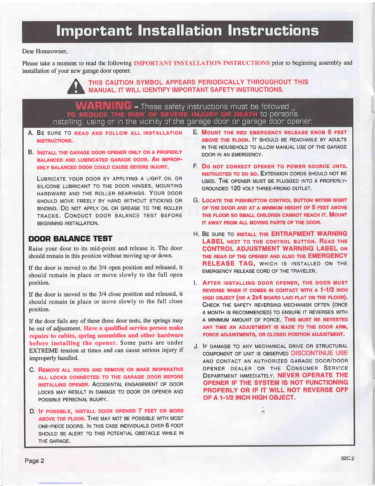
THIS CAUTION
SYMBOL
APPEARS
PERIODICALLY
THROUGHOUT THIS
MANUAL.
IT WILL
IDENTIFY IMPORTANT SAFETY
INSTRUCTIONS.
A. Br suRE
To
READ
AND FoLLow
ALL
rNsrALLATtoN
TNSTRUCnONS.
B.
lnsmll
rHE GARAGE
DooR
opENER oNLY
oN A
PRoPERLY
BALANCED
AND
LUBRICATED
GARAGE DOOR.
AN
ilPROP.
ERLY
BALANCED
DOOR
COULD
CAUSE
SEVERE
INJURY.
LuentcRre
youR
DooR
BY APPLYTNG
A LIcHT olL oR
SILICONE
LUBRICANT
TO
THE DOOR HINGES,
MOUNTING
HARDWARE
AND
THE ROLLER
BEARINGS,
YOUN
OOON
SHOULD
MOVE FREELY
BY
HAND WITHOUT
STICKING OR
BINDING.
DO ruOT
APPLY OIL
OR GREASE
TO THE ROLLER
TRACKS. COI'IOUCT
DOOR
BALANCE TEST
BEFORE
BEGINNING
INSTALLATION,
DOOR
BALANCE
TEST
Raise
your
door to its
mid-point and
release
it, The door
should
remain in this
position
without moving
up or down.
If the
door is
moved to the 314
open
position
and released,
it
should
remain in
place
or move
slowly to
the full open
position.
If the
door
is moved to the
3/4 close
position
and
released,
it
should
remain
in
place
or
move
slowly to
the full close
position.
If the door
fails any of
these three
door
tests, the springs
may
be
out of adjustment.
Ilave
a
qualified
service
person
make
repairs
to cables,
spring
assemblies
and ot[er
hardware
before
installing
the opener.
Some
parts
are
under
EXTREME
tension
at times
and
can cause serious
injury
if
improperly
handled.
C, Reuove
ALL
RopEs
AND
REMovE oR
MAKE INoPERATIVE
ALL LOCKS
CONNECTED
TO
THE GARAGE
DOOR
BEFORE
INSTALLING
OPENER,
ACCIOENTRT
ENGAGEMENT
OF
DOOB
LOCKS
MAY RESULT
IN
DAMAGE
TO DOOR OR
OPENER
AND
POSSIBLE
PERSONAL
INJURY.
D, lr
posslElE,
tNsrALL
DooR
oPENER
7 FEET oR
itoRE
ABOVE
THE
FLOOR. THIS
IUNY
NOT BE
POSSIBLE WITH
MOST
ONE.PIECE
DOORS, Iru
TNIS CASE
INDIVIDUALS
OVER 6
TOOT
SHOULD
BE ALERT
TO THIS
POTENTIAL
OBSTACLE
WHILE
IN
THE GARAGE.
Mouw rHE
RED EUERGENcv
RELEASE KNoB 6
FEET
ABOVE THE FLOOR.
IT
SNOUIO
BE REACHABLE
BY ADULTS
IN THE HOUSEHOLD TO ALLOW
MANUAL USE OF THE GARAGE
DOOR IN AN EMERGENCY.
Do tor coNNEcr opENER
To
powEn
souncE
UNTIL
INSTRUCTED TO DO SO.
EXTTruSION CORDS
SHOULD
NOT BE
USED. THE OPENER
MUST BE PLUGGED
INTO A PROPERLY-
GROUNDED
120 VOIT
THREE-PRONG
OUTLET,
Locnre rHE
pusHBurroN
courRol
BurroN
wtrHtN slcHT
OF THE
DOOR AND AT A MINIIIUM
HEIGTIT OF 5
FEET ABOVE
THE FLOOR SO
SMALL CHILDREN
CANNOT REACH
tI. MOUNT
rT AWAY FROM
ALL MOVING PARTS OF
THE DOOR.
Be suRe ro
rNsrALL rHE ENTRAPMENT
WARNING
LABEL
NExr ro rHE coNTRoL
BUTToN.
Reno rte
CONTROL
ADJUSTMENT
WARNING LABEL
ott
THE REAR OF THE OPENER AND
ALSO THE
EMERGENCY
RELEASE
TAG,
wHrcH
ts TNSTALLED oN
THE
EMERGENCY
RELEASE CORD OF
THE TRAVELER.
Arrsn
TNSTALLING DooR opENER,
THE
DooR MUsr
REVERSE
WHEN IT COMES IN COiITACT
WITII A
1.1/2 II'ICTI
HrcH oBJECT
(On
l2X4 BOARD
LA|D FLAT ON THE
FLOOR).
Cnecr
rHE
sAFEw
REVERSTNG
MEcHANtsM orreru
(oruce
A MoNTH
rs REcoMMENoeo) ro ENSURE
tr REVERSES
wtrH
A MINIMUM AMoUNT oF
FoRcE. Txs uusr BE
RETESTED
ANY Tlf,E AN ADJUSTMENT
lS MADE TO
THE DOOR ARttl'
FORCE ANUSTIiENTS,
OR CLOSED
POSmON AIITUSTilENT.
lp oRtuRee ro ANy MEcHANtcAL
DRtvE
oR srRUcruRAL
COMPONENT
OF UNIT IS OBSERVED
DISCONTINUE
USE
AND coNTAcr
AN AUTHoRtzED
GARAGE
oooR/oooR
opENER
DEALER oR THE Coltsutrlen
SeRvtce
DrpRRrlerur
rMMEDrArELy.
NEVER OPERATE
THE
OPENER
IF
THE
SYSTEM
IS NOT FUNCTIONING
PROPERLY
OR IF
IT WILL
NOT REVERSE
OFF
OF A 1.1/2 INCH
HIGH
OBJECT.
E,
F.
G,
H.
L
J,
Page
2
02c.2
CONTROLS
Your new
garage
door opener offers momentary
control. To
operate
the door
simply
press
either the hand held transmitter
button or the wall mounted
pushbutton
for one to two seconds
and
the
door will
automatically open or close. The opener can
be
stopped
during
any
portion
of the opening or closing cycle
by
pressing
either of the buttons. The next time the button is
pressed,
the opener will re-start the door in motion in
the
opposite direction.
OBSTRUGTION SENSING
When
properly
adjusted, the
door will automatically reverse if
it
senses an obstruction during
the closing cycle. This
system
will also stop
the door if it hits an obstacle when opening.
SAFE.T.CYCLETM
This electronic system will
reverse
the door in 30 seconds or
less if the door is unable to travel to the full closed
position.
This feature
provides
automatic
reversing
should other sys-
tems fail to operate and the
door
does not fully
close.
SAFE.T.SIGNALTM
Lights will flash whenever Safety Reverse or Safe-T-Cycle
has
been activated.
FORCE ADJUSTMENTS
Independent OPEN and CLOSE dials allow
you
to select the
minimum required opening and closing force.
EMERGENCY
RELEASE
Your door
opener is
equipped with
an emergency release
device.
In the
event of a
power
failure, pull
the knob on the
pull
cord down
and slightly
to the back
(away
from door)
allowing the disconnect
to latch. This
will allow
you
to
man-
ually open or close
the door. When
power
has been restored,
gently
pull
the
disconnect cord, releasing
the traveler detent,
then
press
either
the transmitter
or
pushbutton.
The opener
will
automatically reconnect.
SAFE.T.MONITORTM
A dynamic
obstruction
detection device
that continuously
monitors
the amount
of force required to move
the
garage
door, and
automatically
adjusts the obstruction detection level
in addition
to the homeowner
adjustable force levels. This
SAFETY
SYSTEM adds
the additional level
of
protection
indicating
our commitment
to safe
garage
door operation.
CONTROL
CONNECTIONS
All opener
models are
provided
with screw
terminals
for the
attachment
of a wall
mounted
pushbutton
or four-function
wall console.
The console
includes
a
pushbutton,
worklight
switch,
vacation switch,
and
pedestrian
light. Some models
are
provided
with a
pushbutton
only, but ALL MODELS
can
be connected
to the four-function
wall console
which
is
sold
separately.
Voltage
Required: 120
Volts a.c.
60 cycle
Single Phase
A
grounded,
three
(3)
hole
electrical outlet is required.
Motor
Specs:
Permanent
Split Capacitor
-Internal
Automatic Over load Reset
Current
Required:
7
AMPS
Overload
Protection:
The motor is equipped
with an auto-
matic
thermal over load
device. Should the motor
become
over heated,
the
over
load
device will render
the opener inop-
erative.
Simply wait
approximately 5 to 10 minutes
for the
motor to cool.
Opener Length:
Minimum
Head
Room
Required:
Average Door
Speed:
Maximum
Door
Size:
10Feet-8Inches
From
end of tube assembly to
rear
of opener
power
unit.
2
Inches
(Tracked
Doors)
6 Inches
(Trackless
Doors)
6 Inches
per
second
L/4H}.:
16 Ft. Wide / 7 Ft. High
1/3 H.P. or I/2HP.:
18 Ft. Wide l7 ll2Ft.High
03c.1
Page
3
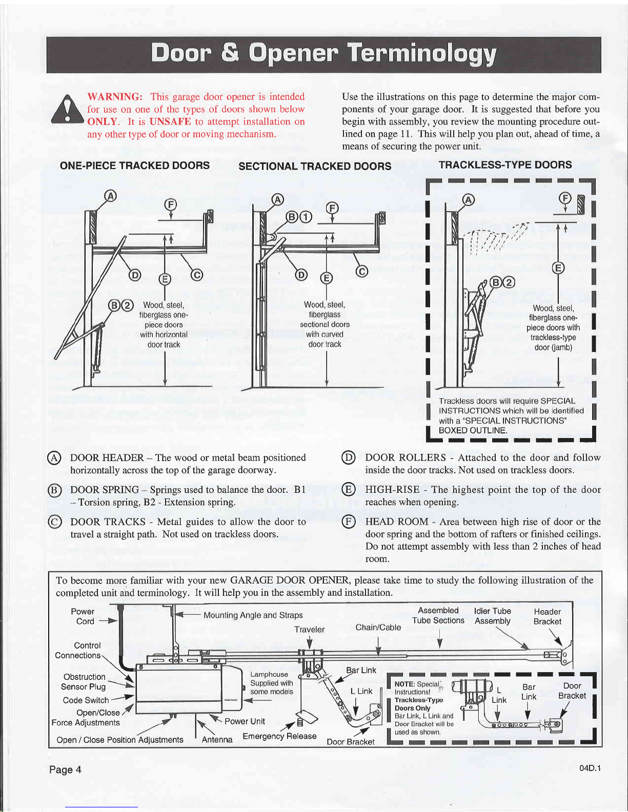
WARNING:
This
garage
door opener
is intended
for use on one of the
types of doors shown below
ONLY.
It is UNSAFE to
attempt installation on
any other type of door or
moving mechanism.
ONE.PIECE TRACKED
DOORS
SECTIONAL TRACKED
DOORS
Use
the
illustrations
on this
page
to determine the major com-
ponents
of
your garuge
door. It is suggested that before
you
begin with
assembly,
you
review the mounting
procedure
out-
lined
on
page
11. This will help
you plan
out, ahead of time, a
means of securing the
power
unit.
TRACKLESS.TYPE
DOORS
I
I
I
I
I
I
I
I
,i:::',x:iJlh
I
'T:5ff:;l',!'
I
@
DOOR HEADER - The wood or metal beam
positioned
horizontally across
the top ofthe
garage
doorway.
DOOR SPRING - Springs
used to balance
the door. 81
-
Torsion spring,
82 - Extension spring.
DOOR TRACKS
-
Metal
guides
to allow the door to
travel a straight
path.
Not used on trackless doors.
@
@
@
I
aoxeo ourLrNE.
I
-IIIIIII
DOOR ROLLERS
-
Attached to the door and
follow
inside
the door tracks. Not used on trackless doors.
HIGH-RISE
-
The highest
point
the top of
the
door
reaches
when opening.
HEAD ROOM - Area between high rise of door or the
door spring and the bottom ofrafters or finished ceilings.
Do not attempt assembly with less than 2 inches of head
room.
To
become
more familiar with
your
new GARAGE DOOR OPENER,
please
take time
to study
the following illustration of the
completed unit and
terminology.
It will help
you
in
the
assembly and installation.
Control
Connections
Power
Cord
Sensor
Plug
Code
Switch
..-i
Open/Close
Force Adjustments
power
Unit
./
Open /
Close Position Adjustments
RnLnna
EmergencyRelease
/tiltguuvtto\
Obstruction
_ \
Bar Link
.f'
-
-o*ll
_y*
l
J
L Link
I
Bar
Link
I
Y
I
l1
Link
V
-./
BracketDoor
Assembled
ldler Tube
Tube
Sections
Assembly
Header
Bracket
\
Page
4
04D.1
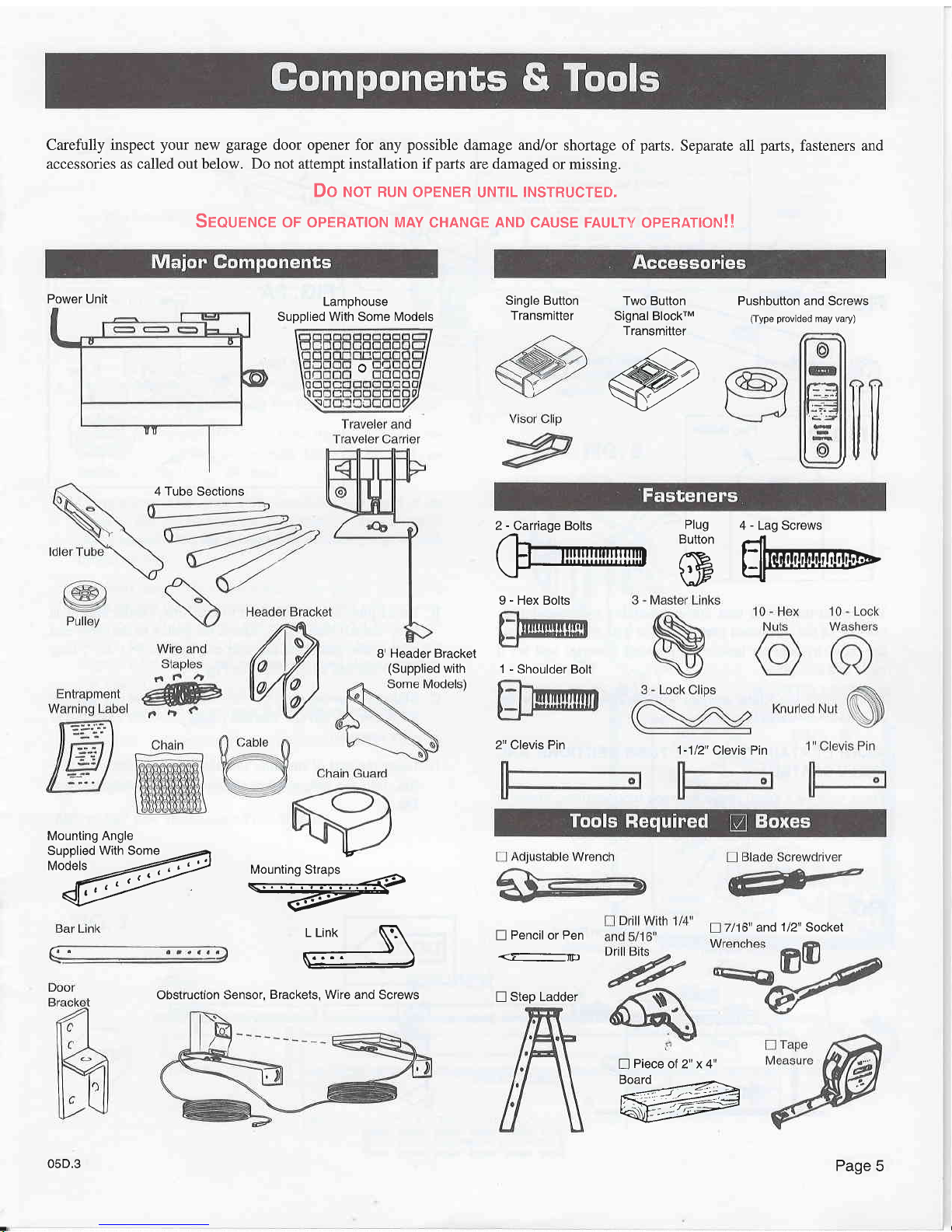
Carefully inspect
your
new
garage
door opener for any
possible
damage and,ior
shortage of
parts.
Separate all
parts,
fasteners and
accessories as called out below. Do not attempt installation if
parts
are damaged or missing.
Oo r'ror nur,r
operrreR uNTrL
TNSTRUcTED,
Srourruce oF opERATroN
MAy
cHANGE
AND
cAUsE FAULTv
opERATroN!!
Pushbutton
and
Screws
(Type provided
may vary)
5" and
1/2"
Socket
n
Piece
of 2" x 4"
,W
Single Button
Transmitter
2" Clevis Pin
n
Pencil
or
Pen
<.F-m)
n
Step Ladder
Power Unit
Lamphouse
Supplied With Some Models
Two Button
Signal BlockrM
Transmitter
.,#
(-\
-YZZ)7
/'
NZ
4 Tube
Sections
05D.3
B'
Header Bracket
(Supplied
with
2 - Carriage Bolts
Plug
4 - Lag Screws
@rofl@'
\'lP
-u
Mounting Angle
rffiry
%
L Link
N\
--) \
\=-
9 - Hex Bolts
1
-
Shoulder Bolt
1-112"
Clevis Pin
obstructron Sensor,
Brackets, Wire
and Screws
I
Page
5
ldler Tube
Assemble Tube
Sections
Align Holes
on the Side
to Make
Assembly
Stronger
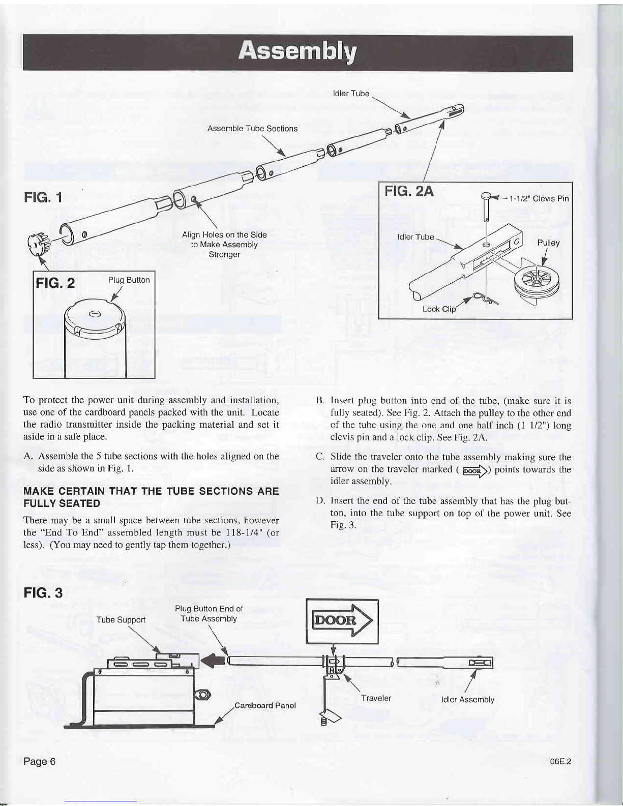
To protect
the
power
unit during assembly and
installation,
use
one of the cardboard
panels packed
with the
unit. Locate
the
radio transmitter inside the packing
material and set it
aside in a safe
place.
A. Assemble the 5 tube sections
with
the holes alisned
on the
side as shown in Fig. 1.
MAKE CERTAIN THAT THE TUBE SECTIONS ARE
FULLY SEATED
There may be a small space
between tube sections,
hou,ever
the "End To End" assembled
length must
be 118-1i4"
(or
less).
(You
may need to
gently
tap
them
together.)
FIG. 3
Tube Support
Insert plug
button into
end of the
tube,
(make
sure it is
fully
seated). See Fig.
2. Attach the
pulley
to the other end
of the
tube using
the one and
one half inch
(l
l/2") long
clevis
pin
and a lock
clip. See Fig.
24.
Slide the
traveler
onto the
tube assembly making
sure the
arrow
on the
traveler marked
(
|D|o6;>)
points
towards the
idler
assembly.
Insert
the
end of the tube
assembly that has the
plug
but-
ton,
into
the tube support
on top of the power
unit. See
Fis.
3.
B.
C.
D
1-112"
Clevis
Pin
FlG. 2
Plug Button
Plug
Button End of
Tube Assembly
ldler Assembly
Page
6
06E.2
ldler
Assembly
FIG. 4
39" to 41" for
Tracked-Type Doors
III-
50" to 52" for
Trackless-Type
Doors
IIII
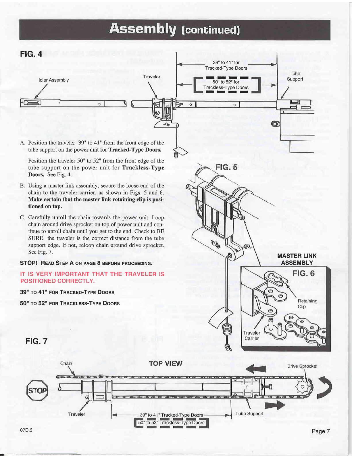
A. Position the traveler 39" to 41" from the front edge of the
tube support on the
power
unit for Tracked-Type Doors.
Position
the traveler 50" to 52"
from the front
edge of the
tube support on the
power
unit for Trackless-Type
Doors. See
Fig. 4.
B. Using a master link assembly, secure the loose end
of the
chain
to the traveler carrier, as shown in Figs.
5 and 6.
Make certain that the master link retaining
clip is
posi.
tioned on top.
C. Carefully unroll the chain towards the
power
unit.
Loop
chain around drive sprocket on top of
power
unit
and con-
tinue to unroll chain until
you get
to the end. Check
to BE
SURE the traveler is the correct distance from
the tube
support edge. If not, reloop chain
around drive sprocket.
See
Fig.
7.
STOP! Rrno Srep A oru
pnce
I
aerone
pRocEEDtNG.
IT IS
VERY IMPORTANT
THAT THE TRAVELER
!S
POSITIONED CORRECTLY.
39"
To 41" FoR Tnncreo-TvpE DooRS
50"
ro
52"
FoR Tnncruess-Tvpe Doons
FIG.
7
Tube
Support
PageT
07D.3
MASTER LINK
ASSEMBLY
I
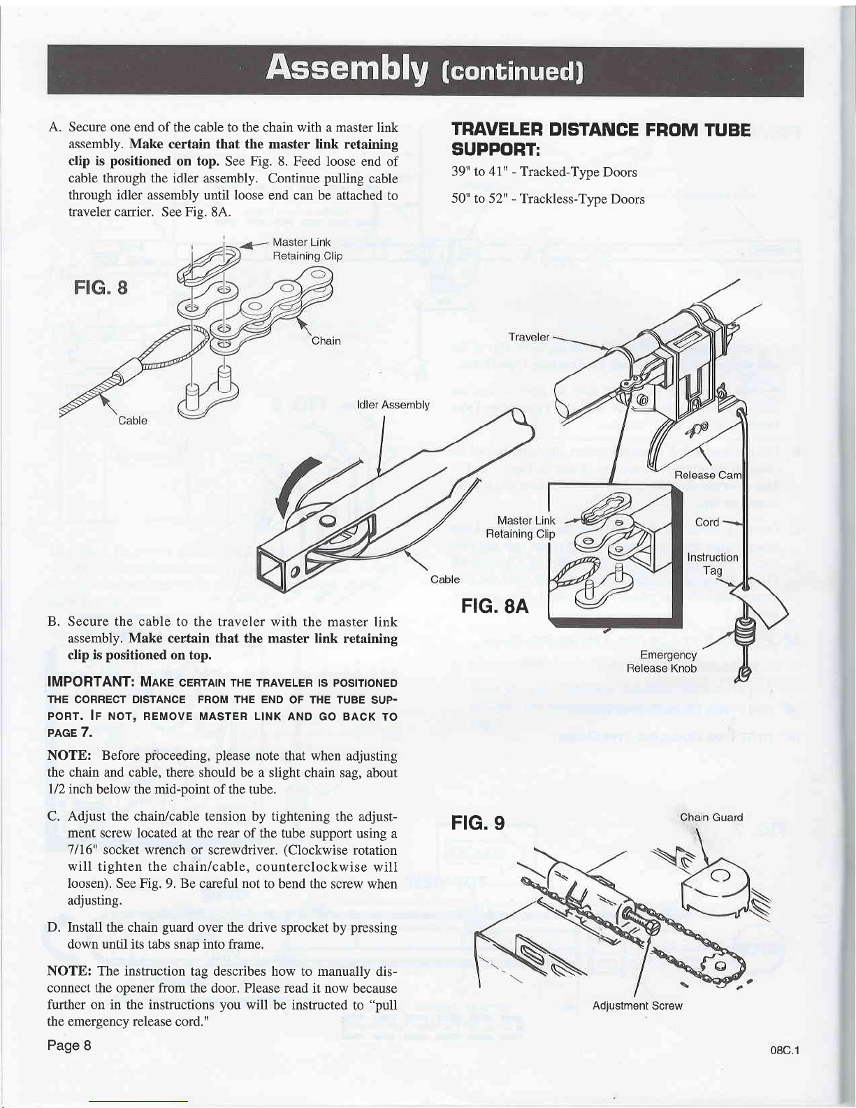
A. Secure one end
of the cable to the chain with a master
link
assembly. Make
certain that the master link retaining
clip is
positioned
on top. See
Fig.
8. Feed loose
end of
cable through the idler
assembly. Continue
pulling
cable
through idler
assembly until
loose
end can be attached
to
traveler carrier.
See
Fis.
8A.
TRAVELER
DISTANCE
FROM
TUBE
SUPPORT:
39" to 41u
-
Tracked-Type
Doors
50"
to 52" - Trackless-Type
Doors
B.
Secure the cable to the
traveler with the master
link
assembly. Make certain that the
master
link
retaining
clip is
positioned
on top.
IMPORTANT: MnrE
cERrAtN THE TRAVELER ts
postnoNED
THE CORRECT DISTANCE FROM THE END
OF THE TUBE
SUP.
PORT, lF NOT, REMOVE MASTER L|NK
AND GO BACK
TO
PAGE 7.
NOTE:
Before
pioceeding, please
note that when
adjusting
the chain
and cable, there should be a slight
chain sag, about
l/2
inch below the mid-point of the tube.
C. Adjust the chain/cable tension by
tightening the
adjust-
ment screw located
at
the rear
of the tube support
using a
7/16"
socket wrench or screwdriver.
(Clockwise
rotation
will tighten the chain/cable,
counterclockwise
will
loosen).
See
Fig.
9.
Be
careful
not
to bend the
screw when
adjusting.
D.
Install the chain
guard
over the drive
sprocket by
pressing
down until its tabs
snap
into frame.
NOTE: The instruction
tag describes how to manually
dis-
connect the opener from
the door. Please read it now
because
further on in the instructions you
will be instructed
to
"pull
the emergency release
cord."
Page
8
FIG.
8A
FIG.
9
Adiustment
Screw
08c.1
IMPORTANT!
lr rs
cRtlcAL
rHAr
you
tDENlFy
wHAr
rypE
OF DOOR YOU
HAVE
AS IT
WILL
MAKE
A DIFFERENCE
IN THE
wAy
youR
opENER
ls INSTALLED,
seE
pnce
4.
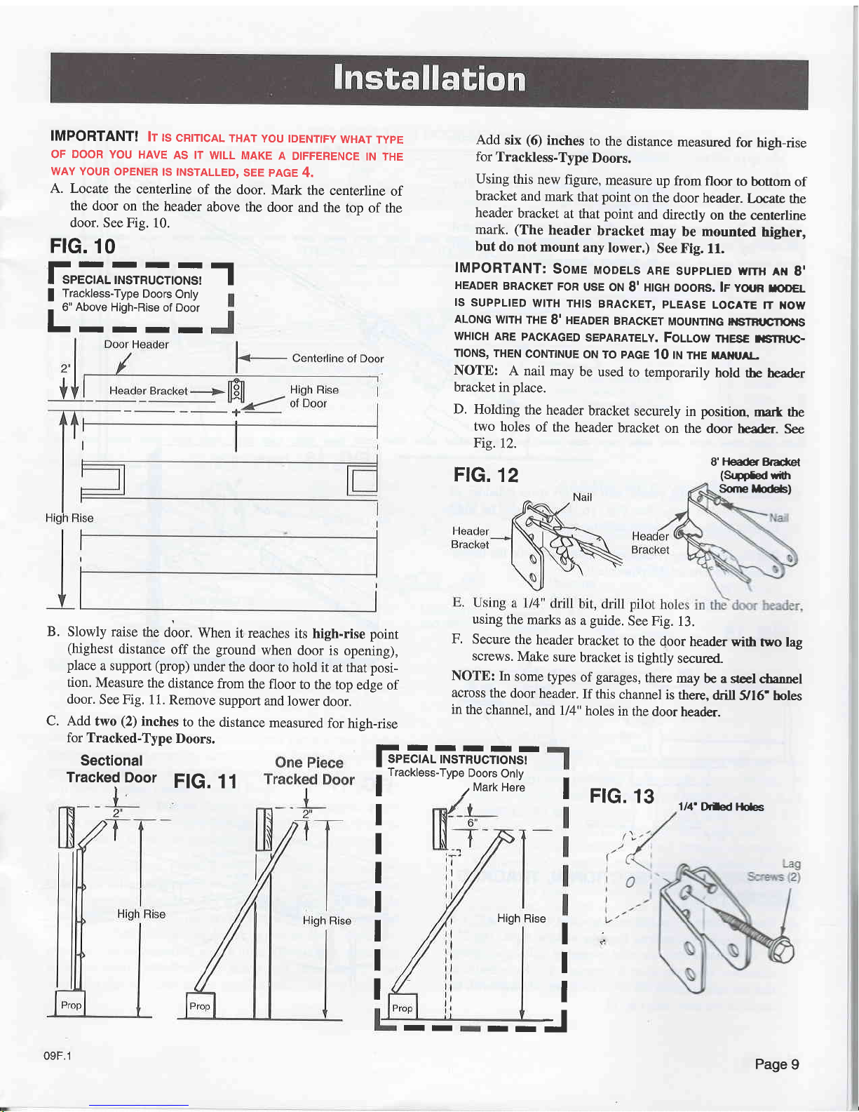
A. Locate
the
centerline
of the
door.
Mark
the centerline
of
the door on
the header
above the
door
and the
top
of the
door, See Fig.
10.
FrG.
10
Add
six
(6)
inches
to
the distance
measured
for high-rise
for
Trackless-Type
Doors.
Using
this
new figure,
measure
up
from floor
to bouom
of
bracket
and mark
that
point
on the
door header.
Laate
the
header
bracket
atthal point
and
directly
on rhe
centerline
mark.
(The
header
bracket
may
be
mounted
higher,
but
do not
mount
any lower.)
See Fig.
11.
IMPORTANT:
Soue
MoDELs
ARE
suppLtEo wmr
rr
g'
HEADER
BRAcKET
FoR
usE
oN
I' HtcH DooRs.
lr voun
rco€L
ls
SUPPL|ED
W|TH
TH|S
BRACKET,
PLEASE
LOCATE
1T xOW
ALoNG
wtrH
THE
8' nEADeR
BRACKET
MouNnNG
FrsrBt
cnot{s
WHICH
ARE
PACKAGED
SEPARATELY.
FOLLOW
THESE T|STRIJC.
TloNs,
THEN
CONTTNUE
ON
TO PAGE
10 rru
rxe rAfllrAt_-
NOTE:
A nail
may
be
used
to temporarily
hold
the header
bracket
in
place.
D.
Holding
the header
bracket
securely
in
position,
mart the
two
holes
of
the header
bracket
on
the door header.
See
Fig.12.
F-rrrT
SPECIAL
INSTRUCTIONS!
T
I
Trackless-Type
Doors
Only
-
6"
Above
Hiqh-Rise
of Door
T-
T
IIITI
B.
C.
Slowly
raise the
door.
When
it reaches
its high.rise point
(highest
distance
off the
ground
when
door is
opening),
place
a support
(prop)
under
the
door
to hold it
at that
pos!
tion. Measure
the
distance
from
the
floor to
the top
edge
of
door.
See Fig.
1 1.
Remove
support
and
lower
door.
Add
two
(2)
inches
to the
distance
measured
for
hieh-rise
for Tracked-Type
Doors.
Sectional
Tracked
Door
FlG.
11
SorellorB)
using
the
marks
as
a
guide.
See Fig.
13.
F.
Secure
the
header
bracket
to
the door
header wift
two lag
screws.
Make
sure
bracket
is
tightly
secured
NOTE:
In
some
types
of
garages,
there
may
be a
geel
chann€l
across
the
door
header.
If
this channel
is
there,
drill
g16.
boles
in
the
channeT,
and I/4"
holes
in
the door
header.
FtG.
12
8'l-leaderBrdet
(Sugftd
*fr
1/4'Drled
lG
I
rrc.
rs
I
I
I
I
I
I
I
High
Rise
t:
I
I
IIIIII
I
SPECTAL
TNSTRUCTTONS!
a
Trackless-Type
Doors
Only
I I
Mark
Here
09F.1
II
II
-J
Page
9

A.
B.
Place
the
power unit on
the
floor
and
raise
the
idler
assem-
bly
up to
the
header
bracket.
See
Fig.
14.
Using
the
2"
clevis
pin and
a
lock clip,
secure
the idler
assembly
to the
header
bracket.
See
Fig.
15.
NOTE:
The
header
bracket
is designed
with
an additional
positioning
hole
if
height
adjustment
is necessary.
It can also
be mounted
upside
down
for
further
adjustment.
Carefully
raise
the
power unit
and set
it
on a
ladder
or
other
suitable
prop. See
Fig.
16. Unit
should
be
high
enough
to clear
door
when
fully
opened'
Pull
the
emergency
release
cord
down
and slide
the
travel-
er assembly
toward
the
Power
unit.
Traveler
Assembly
ONE
PIECE
AND
SECTIONAL
TRACKED
DOORS
ONLY
E. Raise
the
door
to the
full
open
position and
place a2"
x 4"
board
(on
edge)
between
the
tube and
the
door.
The
2" x
4" will
ensure
that the
tube
assembly
will
have
enough
clearance
when
the
door
is opening.
Set
the operator
so
that the
tube
rests
on
the
2" x
4" directly
in line
with the
center
ofthe
door.
See
Fig.
17.
Page
10
FrG.
14
FtG. 17
ldler Assembly
C.
D.
FlG.
15
Header
Brackel
Lock Clip
Fo<
108
 Loading...