

Page 1

WARNINGS
• Always read tool manual before operating.
• Always wear safety glasses while operating or
while in the vicinity of a tool in operation.
• For testing, always cycle tool away from work
to insure proper ring closure. For safety
reasons, an improperly functioning tool must
not be used. When operating tool, never point
or actuate tool other than into work.
• Operate tool in an unobstructed work area.
• Disconnect air supply prior to maintenance
and/or repair of tool.
• Use clean dry air to maximize efficiency. Do
Not Exceed 100 P.S.I. (7.0 kg/cm sq.)
• Do not use bottled gases such as oxygen,
hydrogen, carbon dioxide, acetylene, etc.
• Tools shall be operated with a fitting or hose
coupling on or near the tool in such a manner
that all compressed air in the tool is discharged
at the time the fitting or hose coupling is
disconnected.
SPRING RETURN
PNEUMATIC D-RING TOOL
TR201 TR203
SAFETY INSTRUCTIONS
WARNING:
The employer and/or user must ensure
that proper eye protection is worn. Eye
protection equipment must conform to
the requirements of the American
National Standard Institute, ANSI Z87.1-1989 and
provide frontal and side protection. Eye protection
should be worn by the operator and others in the work
area when loading, operating, or servicing this tool.
Eye protection is required to guard against possible
flying particles and/or debris, which could cause
severe eye injury.
NOTE: Non-side shielded prescription glasses and
faceshields alone do not provide adequate protection.
OPERATION
Always handle tool with care:
• Never engage in horseplay.
• Never pull the trigger unless nose of tool is
directed toward the work.
• Keep others at a safe distance from the tool while
the tool is in operation as actuation occurs,
possibly causing injury. Keep hands and body
away from the jaw mechanism of the tool.
LOADING TOOL
When loading tool:
• Never place a hand or any part of body in jaw
mechanism area of tool.
• Never point tool at anyone.
• Never actuate tool when loading, accidental injury
may occur.
AIR CONSUMPTION
SC7 Series Tools require 1.6 cubic feet per minute
(.045 cubic meters per minute) of free air to operate at
a rate of 100 fasteners per minute, at 100 P.S.I. (7.0
kg/cm sq.).
1 of 6 01/03
Page 2
2 of 6 01/03
Page 3

3 of 6 01/03
Page 4

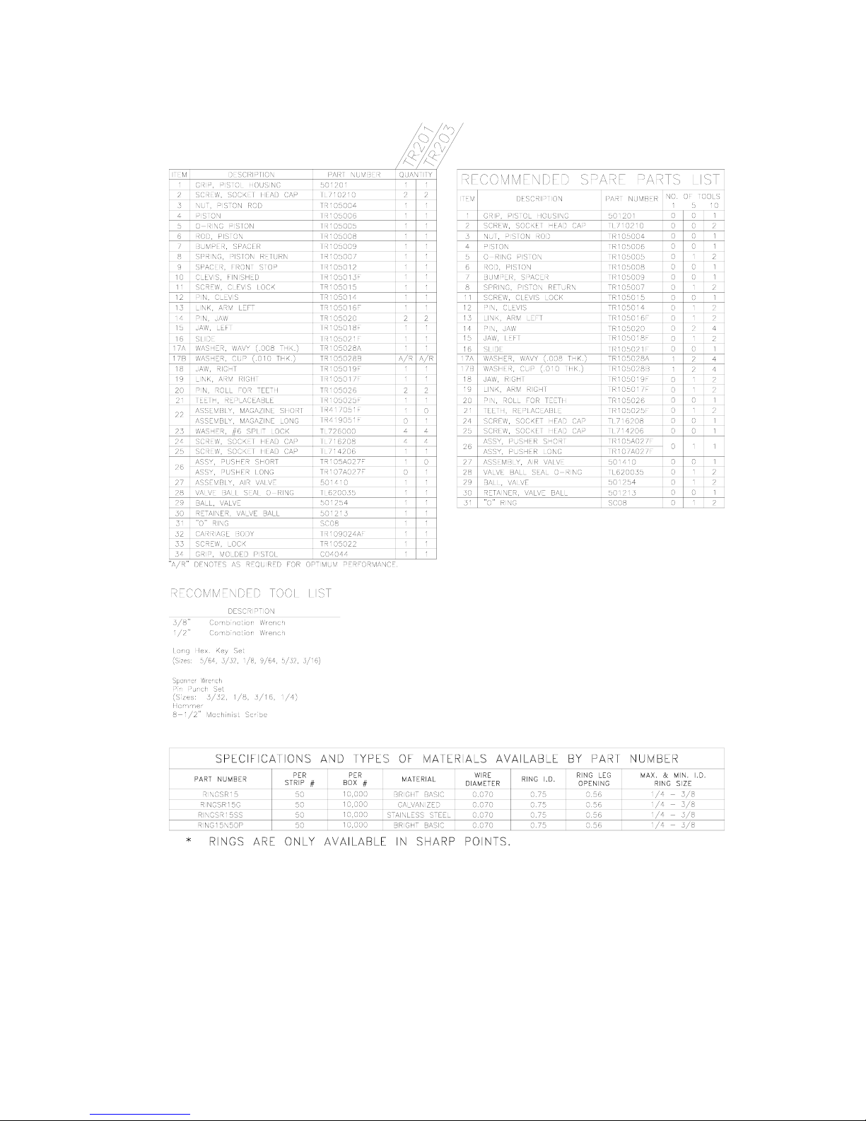
TO DISASSEMBLE
Carriage and magazine assembly
1. Remove (2) socket head cap screws (#2).
2. Remove carriage and magazine assembly from housing
(#1) by turning counter clockwise.
3. Detach magazine assembly (#22) by removing (4) socket
head cap screws (#24) from carriage assembly.
Piston, jaws and teeth
1. Remove o-ring (#5).
2. Remove piston rod nut (#3) from piston rod (#6). Apply
heat as needed to break down thread lock adhesive on
threaded end of piston rod.
3. Remove piston, bumper and spring (#4, #7 and #8).
4. Remove socket head cap screw (#25).
5. Remove slide (#16) by sliding it away from teeth area
and pulling it up through the carriage.
6. Remove jaw assembly from carriage.
7. Drive out pin (#14) from jaws (#15 and #18) and arm
links (#13 and #19).
8. Drive out pin (#12) from arm links (#13 and #19) and
clevis #10).
9. Remove clevis lock screw (#11) from clevis (#10).
10. Remove clevis (#10) from piston rod (#6). Apply heat
as needed to break down thread lock adhesive on
threaded end of piston rod.
11. Detach teeth (#21) by driving (2) roll pins (#20) from
carriage and teeth (#32 and #21).
12. Apply heat as needed to break down thread lock
adhesive on threaded end of piston rod.
13. Detach stop spacer (#9) by removing set screw (#33)
and then use a spanner wrench to remove stop spacer
(#9) from carriage (#32).
Throttle
1. Remove air valve assembly (#27) from housing (#1).
2. Remove o-ring, ball, valve ball retainer and o-ring (#28,
#29, #30 and #31).
TO RE-ASSEMBLE
1. Assemble o-ring, valve ball retainer, ball and o-ring
(#31, #30, #29 and #28) and insert into throttle bore of
housing (#1).
2. Install air valve assembly (#27) into throttle bore of
housing (#1). (Do Not Over-Tighten).
3. Install stop spacer (#9) onto the carriage (#32). Use
Loctite #242 or equivalent.
4. Install set screw (#33) into carriage, locking stop spacer
onto carriage.
5. Install teeth (#21) by driving in (2) roll pins (#20) until
flush with carriage.
6. Connect outer jaw to left arm link (#15 and #13) by
driving roll pin (#14) in aligned holes.
7. Connect inner jaw to right arm link (#18 and #19) by
driving roll pin (#14) in aligned holes. (Make sure you
match the correct jaw with the correct arm link for the
tool to operate correctly.)
8. Connect jaws and arm link assemblies to clevis (#10) by
driving roll pin (#12) into aligned holes.
9. Place piston rod (#6) into a vise with long threaded end
sticking out.
10. Install piston (#4) onto long threaded end of the piston
rod with piston rod nut (#3) and remove from vise. (Use
Loctite #242 or equivalent on both piston and flexlock
nut.)
11. Install bumper and return spring (#7 and #8) onto piston
rod.
12. Place jaws, arm linkage and clevis assembly onto
carriage.
13. Insert piston rod, return spring, bumper and piston
assembly through the carriage and connect to the clevis.
(Use Loctite #242 or equivalent.)
14. Install set screw (#11) into clevis locking piston rod to
clevis.
15. Pivot jaws and arm linkage apart so that the slide (#16)
can be installed onto carriage.
16. Install magazine assembly (#22) with (4) socket head
cap screws (#24).
17. Install o-ring (#5) onto the piston.
18. Apply lubrication to piston, o-ring, threaded stop spacer,
housing bore and thread in housing.
19. Install front end assembly into housing. (Be careful not
to damage the o-ring during installation.) Do not overtighten front end assembly onto the housing.
20. Install (2) socket head cap screws (#2), locking front end
assembly into place. Do not over tighten as damage
could occur to front end assembly.
21. Cycle tool to ensure everything operates freely.
22. Cycle tool with rings in magazine. If tool is picking up
next ring or breaking next ring away from the strip,
disconnect air from tool.
23. Push slide back toward the housing and remove slide.
24. Install wavy washer onto the post of the slide.
25. Re-install slide in tool.
26. Test tool again for picking up next ring. If picking up
next ring, repeat steps 24 through 27.
27. Make sure tool is disconnected from air supply. Push
slide toward teeth area. Install socket head cap screw
(#25) into carriage. This keeps the slide from coming
out during use. If the slide is not pushed forward during
socket head cap screw installation, you will break the
carriage.
FILTER AND REGULATOR
1. The air line should always contain a filter and regulator
unit to provide the tool with a constant flow of clean, dry
air. If moisture and contaminates are allowed to enter
the tool, the tool’s serviceable life will be decreased.
2. The regulator should be set between 70 and 90 psi. (4.8
to 6.2 bar). Never operate this tool beyond 100 psi. (6.9
bar).
4 of 6 01/03
Page 5

LUBRICATION
1. The “TR” series D-Ring tools are designed for long,
trouble-free service with minimal air line lubrication. (If
an in-line lubricator is used, it should be set at the
minimum rate of flow.)
2. Excess oil in the tool will attract dirt, lint, and the
adhesive material used in collating the fasteners,
preventing smooth operation. When lubrication is used,
always use a good grade of 5W non-detergent oil with
no additives.
3. When servicing or repairing tool use lithium grease on
all moving parts.
TIPS ON EXTENDING TOOL LIFE
The serviceable life of the “TR” series tools can be extended
greatly by using the following guidelines:
1. Always use Stanley Fastening brand fasteners. Never
replace worn or broken parts with anything other than
genuine Stanley Fastening parts. Generic fasteners
may shorten the life of your D-Ring tool and will void
the manufacturer’s warranty.
2. Keep your tool(s) clean and dry. Always use clean, dry
air and never exceed the recommended air pressure
noted above.
3. Use of this tool at minimum air pressure required for the
work at hand will greatly extend the life of the tool.
4. Exercise caution not to drop equipment. Tools dropping
onto the floor or ground is a primary reason for parts
replacement.
5. Should the tool leak air in both the triggered and rest
positions, a damaged piston o-ring may be the cause.
Once the piston o-ring has been replaced, lubricate with
lithium grease.
CARRIAGE ASSEMBLY ROTATION
INSTRUCTIONS
The carriage is normally shipped in position #1, magazine
pointing downward, parallel to the handle.
To rotate the carriage to new position, loosen (2) socket head
cap screws (#2). Grasp the handle firmly in one hand, and
the carriage (#32) in the other hand.
With steady force, rotate the two sections. This will enable
you to put the front carriage assembly into any position you
need. Tighten the (2) socket head cap screws (#2).
DO NOT use excessive force when tightening any of the
screws. Screws should be snug but not over-torqued.
HELPFUL HINTS FOR FIELD SERVICE TOOL JAMS
The most common reason for jamming problems in the TR
tool is worn parts. The two most common replaced parts are
the jaws and the pusher assembly.
If tool begins to close ring poorly or spit rings, check for
worn parts.
RING DOES NOT CLOSE COMPLETELY
1. Check air pressure. Line pressure at the tool should be
between 70 and 90 psi (4.8 - 6.2 bar) for most
applications. The tool should never be operated at
pressures exceeding 100 psi (6.90 bar).
2. A 3/8” (9.5 mm) or larger air line should be used with
the “TR” Series Tools. Air lines in excess of 100’ (30.5
meters) in length can cause air volume deficiencies at
the tool which will prevent normal operation.
3. Check for foreign debris in the jaw area. This is
especially true in the area between the jaws and the
carriage.
4. The jaws may be worn from extended use. Check the
ring groove of the jaws. If the grooves are worn
excessively or have a chip out of them, replacing the
jaw(s) is recommended.
5. The arm links or pivot pins may be worn excessively,
replacing the part(s) is recommended.
6. When the tool is used in corrosive applications, light oil
should be applied on a regular basis to the carriage,
jaws, linkages and pins. Unlubricated and/or corroded
jaw linkages may cause the tool to function poorly.
FEEDING PROBLEMS
1. If rings do not feed smoothly through the magazine,
check pusher spring for proper tension. If the magazine
is covered with dirt from field use, clean the magazine
and apply a light coating of oil.
2. When rings feed properly through the magazine but do
not feed into the jaws without spitting out of the tool, or
if the rings sit in the jaw grooves on an angle, check
jaws to insure freedom of movement.
3. NEVER USE LOOSE RINGS IN THE TR201 /
TR203 TOOL.
NOTE:
Tool model number TR201 uses a short magazine/pusher
combination, part numbers TR417051F and TR105A027F,
measuring 6 inches long and capable of holding up to 50
rings.
Tool model number TR203 uses a long magazine/pusher
combination, part numbers TR419051F and TR107A027F,
measuring 11.25 inches long and capable of holding up to
100 rings.
5 of 6 01/03
Page 6

SPECIFICATIONS AND TYPES OF MATERIALS AVAILABLE BY PART NUMBER
Part Number Per
Strip #
RINGSR15 50 10,000 Bright Basic 0.070 0.75 0.56 1/ 4 – 3/8
RINGSR15SS 50 10,000 Stainless Steel 0.070 0.75 0.56 1/ 4 – 3/8
0.56
Per
Box #
Material Wire
Diameter
Ring I.D. Ring Leg
Opening
Operating Range of Tool
TR201 TR203
RINGS ARE ONLY AVAIBLE IN SHARP POINTS
LIMITED WARRANTY
Stanley Fastening Systems warrants to the original retail purchaser that this product is free from defects in
material and workmanship, and agrees to repair or replace, at Stanley Fastening Systems’ option, any defective
product within 60 days from the date of purchase. This warranty is not transferable. It only covers damage
resulting from defects in material or workmanship, and it does not cover conditions or malfunctions resulting
from normal wear, neglect, abuse, or accident.
THIS WARRANTY IS IN LIEU OF ALL OTHER EXPRESS WARRANTIES. ANY WARRANTY OF
MERCHANTABILITY OR FITNESS FOR A PARTICULAR PURPOSE IS LIMITED TO THE DURATION
OF THIS WARRANTY. STANLEY FASTENING SYSTEMS SHALL NOT BE LIABLE FOR ANY
INCIDENTAL OR CONSEQUENTIAL DAMAGES.
Some states do not allow limitations on how long an implied warranty lasts, or the exclusion or limitation of
incidental or consequential damages, so the above limitations or exclusions may not apply to you. This
warranty gives you specific legal rights, and you may also have other rights which vary from state to state.
To obtain warranty service, you must return the product at your expense together with proof of purchase to a
Stanley-Bostitch Regional warranty repair center or you may call us at 1-800-556-6696 or 1-800-832-3080 for
the location of additional authorized warranty service locations in your area.
6 of 6 1/03
 Loading...