

Page 1
TLM30
User Manual
TLM30
ON
www.2helpU.com
Please read these instructions before operating the product.
E
ES
F
P
E
PT
NL
DK
SE
FIN
NO
PL
GR
CZ
RU
HU
SK
SI
BG
RO
EE
LV
LT
TR
HR
Page 2
Figures
A
4
E
B
1
2
TLM30
ON
D
1
3
2
TLM30
ON
C
2
1
6.17ft
USB
2
Page 3
Contents
• User Safety
• Setup
• Operation
• Specications
• Warranty
• Error Codes
Retain all sections of this manual for future reference.
User Safety
WARNING:
Carefully read the Safety Instructions and
Product Manual before using this product. The
person responsible for the product must ensure
that all users understand and adhere to these
instructions.
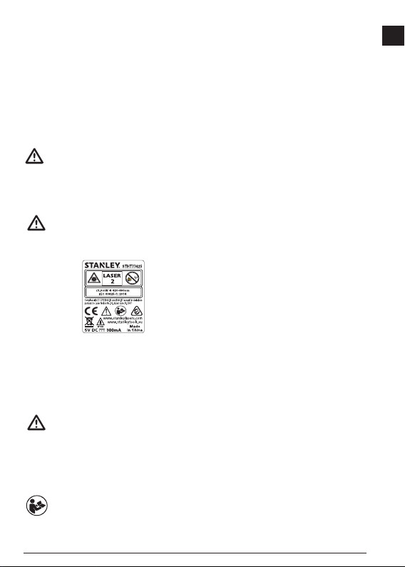
WARNING:
The following label information is placed on your
laser tool to inform you of the laser class for your
convenience and safety.
The TLM30 (STHT77425 or STHT77425W) tool emits
a visible laser beam, as shown in Figure A. The laser
beam emitted is Laser Class 2 per IEC 60825-1 and
complies with 21 CFR 1040.10 and 1040.11 except for
deviations pursuant to Laser Notice No. 50, dated June
24, 2007.
WARNING:
While the laser tool is in operation, be careful not
to expose your eyes to the emitting laser beam
(red light source). Exposure to a laser beam
for an extended time period may be hazardous
to your eyes. Do not look into the beam with
optical aids.
WARNING:
To reduce the risk of injury, the user must read
the product User Manual and the Safety manual.
FCC Compliance
This device complies with Part 15 of the FCC Rules.
Operation is subject to the following two conditions: (1)
This device may not cause harmful interference, and
(2) this device must accept any interference received,
including interference that may cause undesired operation.
FCC Statement
This equipment has been tested and found to comply with
the limits for a Class B digital device, pursuant to part 15
of the FCC rules. These limits are designed to provide
reasonable protection against harmful interference in
a residential installation. This equipment generates, uses,
and can radiate radio frequency energy and, if not installed
and used in accordance with the instructions, may cause
harmful interference to radio communications. However,
there is no guarantee that interference will not occur in
a particular installation. If this equipment does cause
harmful interference to radio or television reception, which
can be determined by turning the equipment off and on,
the user is encouraged to try to correct the interference by
one or more of the following measures:
- Reorient or relocate the receiving antenna.
- Increase the separation between the equipment and
the receiver.
- Connect the equipment into an outlet on a different circuit
(not the circuit to which the receiver is connected).
- Consult the dealer or an experienced radio/TV technician
for help.
Canada, Industry Canada (IC) Notices
Class B digital circuitry of this device complies with
Canadian ICES-003. This device complies with Industry
Canada license-exempt RSS standard(s). Operation is
subject to the following two conditions: (1) this device may
not cause interference, and (2) this device must accept
any interference, including interference that may cause
undesired operation of the device.
Under Industry Canada regulations, the radio transmitter(s)
in this device may only operate using an antenna of a type
and maximum (or lesser) gain approved for the transmitter
by Industry Canada. To reduce potential radio interference
to other users, the antenna type and its gain should be
so chosen that the equivalent isotropically radiated power
(e.i.r.p.) is not more than that necessary for successful
communication.
E
3
Page 4
Setup
E
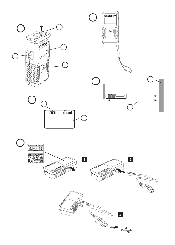
Attaching the Wrist Strap
1.
While facing the front of the tool, insert the thin end of
the wrist strap through one of the holes in the lower
right corner of the tool.
2.
Push the thin end of the wrist strap until it goes
through the other hole.
3.
Separate the two wires, which make up the thin end
of the wrist strap, to form a loop.
4.
Insert the thick end of the wrist strap all the way
through the loop in the thin end, so the wrist strap is
securely fastened to the tool (Figure
Charging the Battery
Fully charge the battery before initial use and whenever
the tool has not been used for 6 months or longer.
1.
Locate the port cover on the side of the tool
(Figure A #4).
2.
Using your finger, gently pull the port cover down
(Figure E #1).
3.
Insert the small end of the USB Recharge Cable into
the port on the side of the tool, making sure to insert
the flat side of the cable into the flat side of the port
E
#2).
(Figure
4.
Insert the USB end of the cable into a USB port in
a computer or USB power outlet (Figure E #3).
5.
Wait approximately 2.5 hours for the battery to fully
charge and then disconnect the USB Recharge
Cable.
When the tool is ON, the battery level appears in the
display window (Figure
D
#1).
Operation
1.
Point the laser at the top of the tool (Figure A #1)
toward the wall whose distance you need to measure
C
#1).
(Figure
2.
Click ON (Figure A #3) to turn the tool on and
display a laser dot on the wall (Figure C #1).
3.
When the bottom of the tool is positioned at the
correct distance from the wall, click
measurement (Figure C #2).
B
).
ON
to take the
4.
View the measurement on the display window
D
(Figure
#2).
Changing the Unit of Measure
Once the current measurement is taken, you can change
the unit of measure from decimal ft (6.21 ft) to fractional
ft (6'02"9/16), fractional ft to meters (1.894 m), meters to
inches (74 9/16 in), or inches to decimal ft.
To change the unit of measurement, press and hold
until you see the measurement change (2-3 seconds).
ON
NOTE: If you continue to hold
changes, the tool will turn off.
after the measurement
Re-measuring
If you need to take a new measurement, click ON.
• The previous measurement (Figure
cleared from the display window.
• When you are ready to take the new measurement,
ON
.
click
D
#2) will be
Turning Off the Tool
The tool can be turned off in either of these ways:
• After taking a measurement, press and hold
5 seconds (until the display window clears).
• If you do not use the tool for 45 seconds, it will
automatically turn off.
ON
for
ON
4
Page 5
Specifications
Range 7in to 30ft (17.5cm to 9m)
Measuring Accuracy* Typically ± 1/4in (± 6mm)*
Resolution** 1/16in (1mm)**
Laser Class Class 2 (IEC/EN60825-1: 2014)
Laser Wavelength ≤ 1.0mW @ 620-690nm
Auto Power Switch-off After 45s
Battery Life Up to 3000 Measurements
Dimension (H x D x W) 2.44 x .69 x 1.25in (62 x 17.5 x 32mm)
Weight
Storage Temperature Range
Operating Temperature Range
*
Measuring Accuracy depends on the current conditions. Under favorable conditions (good target surface and room temperature)
up to 30ft (9m).
**Resolution is the nest measurement you can see. In inches, that is 1/16". In mm, that is 1mm.
or 30 days (if the tool is not used)
1.12oz (31.75g)
14° F ~ 140° F (-10° C ~ +60 C)
32° F ~ 104° F (0° C ~ +40° C)
Warranty
STANLEY warrants this product for a period of (2) years against deficiencies in material and workmanship. This
LIMITED WARRANTY does not cover products that are improperly used, abused, altered, or repaired. Please call
866-786-5924 for more information or return instructions. Unless otherwise noted, STANLEY will repair without cost,
any STANLEY product found to be defective, including parts and labor charges, or at STANLEY’s option, will replace
such tools or refund the purchase price, less the amount for depreciation, in exchange for the defective tool. THIS
LIMITED WARRANTY EXCLUDES ALL INCIDENTAL OR CONSEQUENTIAL DAMAGES. Some states do not
allow the exclusion or limitation of incidental or consequential damages, so these limitations may not apply to you.
This LIMITED LIFETIME WARRANTY gives you specific legal rights that may vary from state to state. In addition to
the warranty, STANLEY Lasers are covered by: 30-Day Money Back Guarantee. If you are not completely satisfied
with the performance of your STANLEY Laser for any reason, you can return it within 30 days from the date of
purchase with a receipt for a full refund.
IMPORTANT NOTE: The customer is responsible for the correct use and care of the instrument. Moreover, the
customer is completely responsible for periodically checking the accuracy of the laser unit, and therefore for the
calibration of the instrument.
Calibration and care are not covered by warranty.
E
5
Page 6

Error Codes
E
Code Description Corrective Action
--- Received Signal Too Weak or
Measuring Time Too Long
--- Received Signal Too High The target is too reective. Use a target plate or change the
--- Too Much Background Light Reduce the background light on the target area.
--- Laser Beam Interrupted Remove any obstacles in the path of the laser beam and repeat
--- Insufcient Battery Recharge the tool's battery.
301 Temperature Too High Allow the tool to cool down to a temperature within the specied
Temperature Too Low Allow the tool to warm up to a temperature within the specied
401 Hardware Error Switch the tool on and off several times. If the hardware error
Use a target plate or change the target surface.
target surface.
the measurement.
Operating Temperature Range.
Operating Temperature Range.
still does not clear, return it to a Service Center or distributor.
6
Page 7

Contenido
• Seguridad del usuario
• Conguración
• Operación
• Especicaciones
• Garantía
• Códigos de error
Conserve todas las secciones de este manual
para futura referencia.
Seguridad del usuario
ADVERTENCIA:
Lea con atención las instrucciones de
seguridad y el manual del producto antes de
usar el producto. La persona responsable
del producto debe asegurarse que todos
los usuarios entiendan y cumplan con estas
instrucciones.
ADVERTENCIA:
La siguiente etiqueta de información
se coloca en su herramienta láser para
informarle sobre la clase de láser para su
comodidad y seguridad.
La herramienta TLM30 (STHT77425 o STHT77425W)
emite un rayo láser visible, como se muestra en la
Figura A. El rayo láser emitido es un Láser Clase 2 en
conformidad con la norma IEC 60825-1 y cumple las
normas 21 CFR 1040.10 y 1040.11, excepto en las
desviaciones en conformidad con lo establecido en Laser
Notice No. 50, del 24 de junio de 2007.
ADVERTENCIA:
Mientras la herramienta láser esté en uso,
tenga cuidado de no exponer sus ojos al
rayo láser (fuente de luz roja). La exposición
a un rayo láser durante un largo periodo de
tiempo podría ser peligroso para sus ojos.
No mire directamente al rayo con ayudas
ópticas.
ADVERTENCIA:
Para reducir el riesgo de lesiones, el usuario
debe leer el Manual de usuario y el Manual
de seguridad.
Conformidad con FCC
Este dispositivo cumple con la Parte 15 del
Reglamento FCC. La operación está sujeta a las dos
condiciones siguientes: (1) Este dispositivo puede
no causar interferencia dañina, y (2) este dispositivo
debe aceptar cualquier interferencia recibida, incluso
las interferencias que pudieran causar operación no
deseada.
Declaración de FCC
Este equipo ha sido probado y cumple con los límites
para dispositivos digitales de clase B, de conformidad
con la parte 15 de las normas FCC. Estos límites
han sido diseñados para proporcionar una protección
razonable contra las interferencias nocivas en
instalaciones residenciales. Este equipo genera,
usa e irradia energía de radiofrecuencia y, si no se
instala y se usa de acuerdo con las instrucciones,
puede causar interferencia perjudicial para las
radiocomunicaciones. No obstante, no existe ninguna
garantía de que no se producirá interferencia en
una instalación determinada. Si este equipo causa
interferencias perjudiciales para la recepción de radio
o televisión, que puede determinarse al encender
y apagar el equipo, el usuario puede tratar de corregir
la interferencia tomando una o varias de las siguientes
medidas:
- Reorientar o reubicar la antena receptora.
- Aumentar la distancia entre el equipo y el receptor.
- Conectar el equipo en un tomacorriente de otro
circuito diferente (no el circuito al que está conectado
el receptor).
- Consulte al vendedor o a un técnico experto en
radio/TV para solicitar su ayuda.
Canadá, Avisos del Ministerio de la Industria de
Canadá (IC)
Los circuitos digitales de clase B de este dispositivo
cumplen con la norma canadiense ICES-003. Este
dispositivo cumple las normas RSS de exención de
licencia del Ministerio de la Industria de Canadá.
La operación está sujeta a las dos condiciones
siguientes: (1) este dispositivo puede no causar
ninguna interferencia nociva, y (2) este dispositivo
debe aceptar cualquier interferencia, incluso las
interferencias que pudieran causar una operación no
deseada del dispositivo.
ES
7
Page 8

De conformidad con las disposiciones del Ministerio
ON
ON
ON
ON
de la Industria de Canadá, el o los radiotransmisores
de este dispositivo sólo pueden funcionar usando una
ES
antena de un tipo y una ganancia máxima (o inferior)
aprobados para el transmisor por el Ministerio de
la Industria de Canadá. Para reducir la potencial
interferencia de radio a otros usuarios, el tipo de
antena y la ganancia deben ser elegidas para que la
potencia radiada isotrópica equivalente (p.i.r.e.) no
sea superior a la necesaria para una comunicación
correcta.
Conguración
Colocación de correa de cintura
1.
Mientras ve hacia el frente de la herramienta, inserte
el extremo delgado de la correa de cintura a través
de uno de los orificios en la esquina inferior derecha
de la herramienta.
2.
Empuje el extremo delgado de la correa de cintura
hasta que pase al otro orificio.
3.
Separe los dos cables, que constituyen el extremo
delgado de la correa de cintura, para formar un lazo.
4.
Inserte el extremo grueso de la correa de cintura
completamente a través del lazo en el extremo
delgado, de forma que la correa de cintura esté
asegurada firmemente a la herramienta (Figura
Carga de la batería
Cargue la batería completamente antes del primer uso y
siempre que la herramienta no se use durante 6 meses
o más.
1.
Coloque la cubierta del puerto en el lado de la
herramienta (FiguraA #4).
2.
Utilizando su dedo, jale suavemente la cubierta de
puerto hacia abajo (Figura E #1).
3.
Inserte el extremo pequeño del Cable de Carga
USB en el puerto en el lado de la herramienta,
asegurándose de insertar el lado plano del cable en
el lado plano del puerto (Figura
4.
Inserte el extremo de USB del cable en el puerto
USB en una computadora o tomacorriente USB
E
#3).
(Figura
5.
Espere aproximadamente 2.5 horas para que
la batería se cargue completamente y después
desconecte el Cable de carga USB.
8
E
#2).
Cuando la herramienta esté ENCENDIDA, se mostrará el
nivel de batería en la pantalla (Figura
Operación
1.
Apunte el láser de la parte superior de la herramienta
(Figura A #1) hacia la pared cuya distancia desea
medir (Figura
2.
Dé clic en ON (Figura A #3) para encender la
herramienta y mostrar un punto láser sobre la pared
(Figura
3.
Cuando la parte inferior de la herramienta esté
colocada en la distancia correcta de la pared, dé
clic en
4.
Vea la medición en la ventana de la pantalla
(Figura D #2).
Cambio de la unidad de medición
Después de tomar la medición actual, puede cambiar
la unidad de medida de pies decimales (6.21 pies)
a fracciones de pie (6'02"9/16), de fracciones de pie
a metros (1.894 m), de metros a pulgadas (74 9/16 pulg.),
o de pulgadas a pies decimales.
Para cambiar la unidad de medición, presione
y sostenga
(2-3 segundos).
B
).
NOTA: Si continúa sosteniendo
la medición, la herramienta se apagará.
Re-medición
Si necesita tomar una nueva medición, dé clic en ON.
• La medición anterior (Figura
ventana de la pantalla.
• Cuando esté listo para tomar la nueva medición, dé
clic en
Apagado de la herramienta
Puede apagar la herramienta de cualquiera de estas
formas:
• Después de tomar una medición, presione y sostenga
pantalla se borre).
• Si no utiliza la herramienta por un plazo de
45 segundos, se apagará automáticamente.
C
#1).
C
#1).
ON
para tomar la medición (Figura C #2).
hasta que vea el cambio de medición
D
#2) se borrará de la
.
por 5 segundos (hasta que la ventana de la
D
#1).
después que cambie
Page 9

Especificaciones
Alcance 7 pulg. a 30 pies (17.5cm a 9m)
Precisión de la medición* Típicamente ± 1/4pulg. (± 6mm)*
Resolución** 1/16 pulg. (1 mm)**
Clase de láser Clase 2 (IEC/EN60825-1: 2014)
Longitud de onda de láser ≤ 1.0mW @ 620-690nm
Apagado automático Después de 45s
Vida de batería Hasta 3000 mediciones
Dimensiones (A x A x L) 2.44 x .69 x 1.25pulg. (62 x 17.5 x 32mm)
Peso
Rango de temperatura de
almacenamiento
Rango de temperatura de
operación
*
La precisión de la medición depende de las condiciones actuales. En condiciones favorables (buena supercie del objetivo
y temperatura ambiente) hasta 30pies (9m).
**La resolución es la medición más na que se puede ver. En pulgadas, esto es 1/16". En milímetros, esto es 1 mm.
o 30 días (si no se usa la herramienta)
1.12oz (31.75g)
14 °F ~ 140 °F (-10 °C ~ +60 °C)
32° F ~ 104° F (0° C ~ +40° C)
Garantía
STANLEY garantiza este producto por un periodo de (2) años contra defectos en material y mano de obra. Esta
GARANTÍA LIMITADA no cubre productos que se utilicen inadecuadamente, sometidos a abuso, alterados,
o reparados. Por favor llame al 866-786-5924 respecto a información adicional o instrucciones de devolución.
A menos que se indique de otra manera, STANLEY reparará sin costo cualquier producto STANLEY que se
encuentre que está defectuoso, incluyendo partes y cargos de mano de obra, o a opción de STANLEY, reemplazará
tales herramientas o reembolsará el precio de compra, menos la cantidad por depreciación, por intercambio
de la herramienta defectuosa. ESTA GARANTÍA LIMITADA EXCLUYE TODOS LOS DAÑOS INCIDENTALES
O POR CONSECUENCIA. Algunos estados no permiten la exclusión o limitación de daños incidentales o por
consecuencia, así que estas limitaciones pueden no aplicar para usted. Esta GARANTÍA LIMITADA DE POR
VIDA le proporciona derechos legales que pueden variar de un estado a otro. Además de la garantía, los Láseres
STANLEY están cubiertos por: Garantía de 30 días de devolución del dinero. Si no está totalmente satisfecho con
la operación de su Láser STANLEY, por cualquier motivo, podrá devolverlo dentro del plazo de 30 días desde la
fecha de compra, junto con un comprobante de compra, y recibirá el reembolso completo, sin tener que responder
a ninguna pregunta.
NOTA IMPORTANTE: El cliente es responsable por el uso y cuidado correctos del instrumento. Además, el cliente
es completamente responsable de la verificación periódica de la precisión de la unidad láser, y por lo tanto por la
calibración del instrumento.
La calibración y el cuidado no están cubiertos por la garantía.
ES
9
Page 10

Códigos de error
Código Descripción Acción correctora
ES
--- Señal recibida muy débil
o tiempo de medición
demasiado largo
--- La señal recibida es
demasiado alta
--- Demasiada luz de fondo Reduzca la luz de fondo en la zona del objetivo.
--- Rayo láser interrumpido Retire cualquier obstáculo en la trayectoria del rayo láser
--- Batería insuciente Recargue la batería de la herramienta.
301 Temperatura demasiado alta Deje que la herramienta se enfríe a la temperatura indicada
Temperatura demasiado baja Deje que la herramienta se caliente hasta la temperatura
401 Error de hardware Encienda y apague la herramienta varias veces. Si el error
Utilice una placa de objetivo o cambie la supercie de
objetivo.
El objetivo es demasiado reejante. Utilice una placa de
objetivo o cambie la supercie de objetivo.
y repita la medición.
en Rango de temperatura de operación.
indicada en el Rango de temperatura de operación.
de hardware no se elimina todavía, regrésela a un Centro de
servicio o distribuidor.
10
Page 11

Table des matières
• Sécurité de l'utilisateur
• Conguration
• Fonctionnement
• Caractéristiques
• Garantie
• Codes d’erreurs
Conservez toutes les sections de ce manuel pour
référence ultérieure.
Sécurité de l'utilisateur
AVERTISSEMENT :
Lisez attentivement les consignes de sécurité
et le manuel du produit avant d'utiliser
l'appareil. La personne responsable du
produit doit s'assurer que tous les utilisateurs
ont compris et respectent ces instructions.
AVERTISSEMENT :
Les étiquettes d'informations suivantes sont
apposées sur votre outil laser an de vous
informer de la classication du laser pour des
raisons de commodité et de sécurité.
Le outil TLM30 (STHT77425 or STHT77425W) émet un
faisceau laser visible, comme illustré par la figure A. Le
faisceau laser émis est de classe 2 selon la norme IEC
60825-1 et il est conforme à la norme 21 CFR 1040.10 et
1040.11, excepté les écarts conformément à l’avis sur le
laser n°50 du 24 juin 2007.
AVERTISSEMENT :
Lorsque l'outil laser est en marche,
assurez-vous de ne pas exposer vos yeux
au faisceau laser émis (source lumineuse
rouge). L'exposition à un faisceau laser
pendant une période prolongée peut être
dangereuse pour vos yeux. Ne pas regarder
directement vers le faisceau avec des
accessoires optiques.
AVERTISSEMENT :
An de réduire le risque de blessure,
l'utilisateur doit lire le manuel d'utilisation et le
manuel de sécurité.
Conformité à la FCC
Cet appareil est conforme à la partie 15 de la
réglementation de la FCC. Son fonctionnement est
assujetti aux deux conditions suivantes : (1) cet
appareil ne peut pas causer du brouillage préjudiciable
et (2) cet appareil doit accepter toute interférence
reçue, notamment les interférences qui peuvent
entraîner un fonctionnement non désiré.
Déclaration de la FCC
Cet équipement a été testé et il est conforme aux
limites de la classe B des équipements numériques,
conformément à la partie 15 de la réglementation
de la FCC. Ces limites sont prévues pour offrir
une protection raisonnable contre le brouillage
préjudiciable dans une installation résidentielle. Cet
équipement génère, utilise, peut émettre de l'énergie
de fréquence radio et, s'il n'est pas installé ou utilisé
conformément aux instructions, peut entraîner un
brouillage préjudiciable aux communications radio.
Cependant, il n'y a pas de garantie que ce brouillage
se produira dans une installation particulière. Si cet
équipement cause du brouillage préjudiciable à la
réception de la radio ou de la télévision, qui peut être
déterminé en allumant et éteignant l'équipement,
l'utilisateur est incité à corriger le brouillage par une ou
plusieurs de mesures suivantes :
- Réorientez ou déplacez l'antenne réceptrice.
- Augmentez l'espace séparant l'équipement du
récepteur.
- Branchez l'équipement dans une prise de courant
faisant partie d'un circuit différent (autre que celui
auquel le récepteur est branché).
- Consultez le détaillant ou un technicien en radio/
télévision pour obtenir de l'aide.
Canada, Avis d’Innovation, Sciences et
Développement économique Canada (ISDE)
Le circuit numérique de classe B de cet équipement
est conforme à la norme canadienne ICES-003. Cet
équipement est conforme à la (aux) norme(s) RSS
d’Innovation, Sciences et Développement économique
Canada exempte(s) de licence. Son fonctionnement
est assujetti aux deux conditions suivantes : (1) Cet
appareil ne doit pas provoquer d'interférences, et (2)
cet appareil doit accepter les interférences reçues,
dont celles pouvant provoquer un fonctionnement
indésirable de l’appareil.
F
11
Page 12

Conformément à la réglementation d’Innovation,
Sciences et Développement économique Canada,
le transmetteur radio de cet appareil peut seulement
fonctionner à l’aide d’une antenne du type et du gain
maximum (ou moins) approuvé pour les transmetteurs
F
par Innovation, Sciences et Développement
économique Canada. An de réduire les interférences
radio potentielles aux autres utilisateurs, le type
de l'antenne et son gain doivent être choisis pour
que la puissance isotrope rayonnée équivalente ne
dépasse pas le minimum nécessaire à une bonne
communication.
Conguration
Fixer un bracelet antistatique
1.
En faisant face à l’outil, insérez le bout mince du
bracelet antistatique dans un des trous dans le coin
inférieur droit de l’outil.
2.
Poussez le bout mince du bracelet antistatique
jusqu’à ce qu’il passe dans l’autre trou.
3.
Séparez les deux fils, qui constituent le bout mince du
bracelet antistatique, pour former une boucle.
4.
Insérez le bout large du bracelet antistatique à travers
la boucle dans le bout mince pour que le bracelet
antistatique se fixe de façon sécuritaire à l’outil (Figure
B
).
Charger la pile
Chargez complètement le bloc-piles avant la première
utilisation et lorsque l'outil n'est pas utilisé durant six
mois ou plus.
1.
Trouvez le couvercle du port sur le côté de l’outil
(Figure A no4).
2.
Utilisez votre doigt, tirez doucement couvercle du port
vers le bas (Figure E no1).
3.
Insérez le petit bout du câble de recharge USB dans
le port sur le côté de l’outil tout en vous assurant
d’insérer le côté plat du câble dans le côté plat du port
E
no2).
(Figure
4.
Insérez l’extrémité USB du câble dans le port USB
d’un ordinateur ou une prise d'alimentation USB
E
no3).
(Figure
5.
Attendez environ 2,5 heures pour que la pile soit
complètement chargée, puis déconnectez le câble de
recharge USB.
12
Lorsque l'outil est allumé, le niveau de puissance de la
pile apparaît dans la fenêtre d'affichage (Figure
D
no1).
Fonctionnement
1.
Pointez le laser situé en haut de l'outil (Figure A no1)
vers le mur ou l'objet dont vous voulez mesurer la
distance (Figure
2.
Cliquez sur ON (Figure A no3) pour allumer l’outil
et afficher le point du laser sur le mur
(Figure
3.
Lorsque le bas de l’outil est placé à la bonne
distance du mur, cliquez sur
(Figure
4.
Voyez la mesure dans la fenêtre d’affichage
(Figure
Changer l'unité de mesure
Une fois la mesure prise, vous pouvez changer l'unité de
mesure de pieds décimaux (6,21 pi) à pied en fractions
(6 pi 2 po 9/16), de pied en fractions à mètres (1,894 m),
de mètres à pouces (74 9/16 po) ou de pouces à pieds
décimaux.
Pour changer l’unité de mesure, appuyez et maintenez
ON
jusqu’à ce que l’unité de mesure (2 à 3 secondes).
REMARQUE : Si vous continuez à maintenir
les changements de mesure, l’outil s’éteindra.
Mesurer de nouveau
Si vous devez prendre une nouvelle mesure, cliquez
ON
sur
• La mesure précédente (Figure
la fenêtre d’affichage.
• Lorsque vous êtes prêt à prendre une nouvelle mesure,
cliquez sur
Éteindre l'outil
L'outil peut être éteint de l'une ou l'autre de ces façons :
• Après avoir mesuré, appuyez et maintenez
pendant 5 secondes (jusqu'à ce que l'écran d'affichage
s'éteigne).
• Si vous n'utilisez pas l'outil pendant 45 secondes, il
s'éteint automatiquement.
C
no1).
C
no1).
ON
C
no2).
D
no2).
pour mesure
ON
après
.
D
no2) sera effacée de
ON
.
ON
Page 13

Caractéristiques
Portée 7 po à 30 pi (17,5 cm à 9 m)
Précision des mesures* Généralement ± 1/4 po (± 6mm)*
Résolution** 1/16 po (1 mm)**
Classe de laser Classe 2 (IEC/EN60825-1 : 2014)
Longueur d'onde du laser ≤ 1,0mW à 620-690nm
Fermeture automatique Après 45 s
Durée de vie de la pile Jusqu’à 3000 mesures
Dimensions (H x P x L) 2,44 x 0,69 x 1,02 po (62 x 17,5 x 32 mm)
Poids
Plage de températures de
stockage
Plage de températures de
fonctionnement
*
La précision de la prise de mesure dépend des conditions actuelles Si les conditions sont favorables (bonne surface de la cible
et bonne température de la pièce) jusqu'à 33 pi (9 m).
**La résolution est la meilleure des mesures que vous puissiez voir. En pouces, 1/16 po. En mm, 1 mm.
ou 30 jours (si l’outil n’est pas utilisé)
1,12oz (31,75g)
14° F ~ 140° F (-10° C ~ +60 C)
32° F ~ 104° F (0° C ~ +40° C)
Garantie
STANLEY garantie ce produit pour une période de (2) ans contre les défauts de matériaux et de fabrication. Cette
GARANTIE LIMITÉE ne couvre pas les produits qui sont utilisés, négligés, altérés ou réparés de façon inappropriée.
Veuillez téléphoner au 866-786-5924 pour plus de renseignements ou consultez de nouveau les instructions.
Sauf indication contraire, STANLEY réparera sans frais tout produit STANLEY qui s’avère défectueux, incluant les
pièces et les coûts de la main-d'œuvre ou, à sa discrétion, STANLEY remplacera ces outils ou remboursera le prix
d’achat, moins le montant de la dépréciation, en échange de l’outil défectueux. LA GARANTIE LIMITÉE EXCLUT
TOUS LES DOMMAGES ACCESSOIRES OU INDIRECTS. Certaines provinces ne permettent pas l'exclusion
ou la limitation de dommages accessoires ou indirects, alors cette exclusion peut ne pas s'appliquer à vous. Cette
GARANTIE LIMITÉE À VIE vous donne des droits légaux particuliers qui varient d’une province à l’autre. En plus
de cette garantie, les lasers STANLEY sont couverts par : Garantie de remboursement de 30 jours. Si vous deviez,
pour une quelconque raison, ne pas être entièrement satisfait du niveau de performance de votre laser STANLEY,
vous pouvez le renvoyer, avec sa facture, dans un délai de 30 jours à partir de leur date d'achat, pour vous le faire
rembourser.
REMARQUE IMPORTANTE : Le client est responsable de la bonne utilisation et du bon entretien de l’instrument.
De plus, le client est entièrement responsable de la vérification périodique de la précision de l’appareil laser et par
conséquent, du calibrage de l’instrument.
Le calibrage et l’entretien ne sont pas couverts pas la garantie.
F
13
Page 14

Codes d’erreurs
Code Description Action corrective
--- Signal reçu trop faible ou délai
F
de la prise de mesure trop long
--- Signal reçu trop élevé La cible est trop rééchissante. Utilisez une plaque cible ou
--- Trop de lumière en arrière-plan Réduisez la lumière à l'arrière-plan de la zone cible.
--- Interruption du faisceau laser Retirez tout obstacle de la trajectoire du faisceau laser et
--- Pile insufsante Rechargez la pile de l’outil.
301 Température trop élevée Laissez refroidir l’outil à une température comprise dans la
Température trop faible Laissez réchauffer l’outil à une température comprise dans la
401 Erreur de matériel Éteignez et rallumez l'outil plusieurs fois. Si l’erreur de matériel
Utilisez une plaque cible ou changez la surface cible.
changez la surface cible.
répétez la mesure.
plage de températures de fonctionnement indiquée.
plage de températures de fonctionnement indiquée.
ne s’efface toujours pas, retournez l’outil au service à la
clientèle ou au distributeur.
14
Page 15

Índice
• Segurança do usuário
• Conguração
• Funcionamento
• Especicações
• Garantia
• Códigos de Erro
Guarde todas as seções deste manual para
consulta futura.
Segurança do Usuário
AVISO:
Leia com atenção as instruções de
segurança e o manual do produto antes de
utilizar este produto. A pessoa responsável
pelo produto deve assegurar que todos
os usuários entendam e respeitem estas
instruções.
AVISO:
As seguintes informações das etiquetas
estão xadas na ferramenta laser para
informar sobre a classe do laser para sua
comodidade e segurança.
A ferramenta TLM30 (STHT77425 ou STHT77425W)
emite um feixe laser visível, como mostrado na Figura A.
O feixe laser emitido é de classe 2 de acordo com a IEC
60825-1 e está em conformidade com 21 CFR 1040.10
e 1040.11, exceto os desvios indicados no aviso relativo
ao laser n.º 50, de 24 de junho de 2007.
AVISO:
Quando a ferramenta laser estiver em
funcionamento, tenha cuidado para não
expor os olhos ao feixe de laser emissor
(fonte de luz vermelha). A exposição a um
feixe laser durante um intervalo prolongado
pode ser perigoso para os olhos. Não olhe
para o feixe com próteses oculares.
AVISO:
Para reduzir o risco de ferimentos, o usuário
deve ler o Manual do Usuário do Produto,
o Manual de Segurança.
Conformidade FCC
Este dispositivo está em conformidade com a Parte
15 das Regras da FCC. O funcionamento está sujeito
às duas seguintes condições: (1) Este dispositivo
não pode causar interferências nocivas, e (2) este
dispositivo tem de aceitar quaisquer interferências
recebidas, incluindo interferências que possam causar
um funcionamento indesejado.
Declaração da FCC
Este equipamento foi testado e está em conformidade
com os limites de um dispositivo digital de classe B,
em conformidade com a parte 15 das regras da FCC.
Estes limites foram concebidos para fornecer uma
proteção razoável contra interferências nocivas em
uma instalação residencial. Este equipamento gera,
utiliza e pode irradiar radiofrequência e, se não for
instalado e utilizado de acordo com as instruções,
pode causar interferências nocivas nas comunicações
por radiocomunicação. Contudo, não há garantia
que não ocorram interferências em uma instalação
especíca. Se este equipamento realmente causar
interferências prejudiciais na recepção de televisão
ou rádio, o que pode ser vericado ao ligar e desligar
o equipamento, o usuário deve tentar corrigir as
interferências realizando uma ou mais das seguintes
medições:
- Reoriente ou reposicione a antena de recepção em
outra posição.
- Aumente a distância entre o equipamento
e o receptor.
- Ligue o equipamento na tomada em um circuito
diferente (não deve ser o mesmo circuito ao qual
o receptor está ligado).
- Consulte o fornecedor ou um técnico de rádio/
televisão para obter ajuda.
Canadá, avisos da Industry Canada (IC)
Os circuitos digitais de classe B deste dispositivo
estão em conformidade com a norma canadense
ICES-003. Este dispositivo está em conformidade
com a(s) norma(s) RSS isenta(s) de licença da
Industry Canada. O funcionamento está sujeito às
duas seguintes condições: (1) este dispositivo não
pode causar interferências, e (2) este dispositivo
deve aceitar quaisquer interferências, incluindo
PT
15
Page 16

interferências que possam causar um funcionamento
indesejado do dispositivo.
De acordo com os regulamentos da Industry Canada,
o(s) radiotransmissor(es) neste dispositivo só pode
funcionar com uma antena especíca e um ganho
máximo (ou inferior) aprovado para o transmissor
PT
pela Industry Canada. Para reduzir possíveis radiointerferências de outros usuários, o tipo de antena
e o respectivo ganho devem ser escolhidos de modo
que a potência isotrópica radiada equivalente (e.i.r.p.)
não seja superior à necessária para uma comunicação
bem-sucedida.
Conguração
Como colocar a correia de Pulso
1.
Com a ferramenta voltada para a frente, insira
a ponta fina da correia de pulso passando por um
dos furos no canto inferior direito da ferramenta.
2.
Empurre a extremidade fina da correia de pulso até
que passe pelo buraco.
3.
Separe os dois fios, que compõem a extremidade
fina da correia de pulso, para formar um laço.
4.
Insira a extremidade mais grossa da correia de pulso
passando-a completamente o laço na extremidade
mais fina de modo que a correia de pulso fique presa
à ferramenta de forma segura (figura
Como carregar a bateria
Carregue completamente a bateria antes da primeira
utilização, bem como sempre, quando a ferramenta não
foi utilizada 6 meses ou mais tempo.
1.
Encontre a tampa da entrada da bateria na parte
lateral da ferramenta (Figura
2.
Puxe para baixo com o dedo a tampa da entrada
(Figura E n.º 1).
3.
Insira a ponta do cabo de recarga USB dentro da
porta localizada na lateral da ferramenta. Certifiquese de inserir o lado achatado do cabo dentro do lado
achatado da porta (Figura
4.
Insira a ponta do USB do cabo dentro da porta USB
em um computador ou uma tomada elétrica USB
E
n.º 3).
(Figura
16
E
A
n.º 2).
n.º 4).
5.
Espere aproximadamente 2,5 horas para que
a bateria fique completamente carregada e depois
desconecte o cabo recarregável USB.
Quando a ferramenta estiver ligada, o nível de carga das
baterias aparecerá no display (Figura
D
n.º 1).
Funcionamento
1.
Aponte o laser na parte superior da ferramenta
(Figura n.º 1) para a parede ou o objeto, cuja
distância você precisa medir (Figura
2.
Aperte ON (Figura A n.º 3) para ligar a ferramenta
e exibir o ponto do laser (Figura
3.
Quando a parte inferior da ferramenta estiver
posicionada na distância correta, aperte
fazer a medição (Figura C n.º 2).
4.
Visualizar a medição na janela do display
(Figura D n.º 2).
Como alterar a unidade de medida
Depois que medição de corrente tiver sido realizada, você
poderá alterar a unidade de medida de pés decimais
(6,21 pés) para pés fracionais (6'02"9/16), pés fracionais
para metros (1,894 m), metros para polegadas
(74 9/16 pol.), ou de polegadas para pés decimais.
B
).
Para mudar a unidade de medida, pressione se segure
pressionando
(2-3 segundos).
NOTA: Se continuar segurando pressionado
a medição, a ferramenta se desligará.
ON
até visualizar a última medição
Medir novamente
Se precisar fazer uma nova medição, aperte ON.
• A medição anterior (Figura
do display.
• Ao terminar a nova medição, aperte
Como desligar a ferramenta
A ferramenta pode ser desligada de uma das seguintes
maneiras:
• Após fazer a medição, pressione e mantenha
pressionado
o display se apagar).
• Se não utilizar a ferramenta durante 45 segundos, ela
se desligará automaticamente.
ON
durante vários segundos (até
C
n.º 1).
C
n.º 1).
D
n.º 2) desaparecerá
ON
.
ON
para
ON
após
Page 17

Especificações
Faixa 7 pol. a 30 pés (.17,5 cm a 9 m)
Precisão de Medição* Geralmente ± 1/4in (± 6 mm)*
Resolução** 1/16 pol. (1 mm)**
Classe do Laser Classe 2 (IEC/EN60825-1: 2014)
Comprimento da onda do laser ≤ 1,0 mW a 620-690 nm
Desligamento automático Após 45s
Vida da bateria Até 3000 medições
Dimensões (A x D x L) 2,44 x .69 x 1,25 pol. (62 x 17,5 x 32 mm)
Peso
Faixa de Temperatura de
Armazenamento
Faixa de Temperatura
Operacional
*
*A precisão de medição depende das condições correntes: Em condições favoráveis (boa superfície alvo e temperatura
ambiente) até 9 m (30 pés).
**A resolução corresponde à mais precisa medição possível. Em polegadas, corresponde a 1/16". Em mm, corresponde a 1 mm.
ou 30 dias (se a ferramenta não for usada)
1,12 oz (31,75g)
-10 °C ~ +60 °C (14 °F ~ 140 °F)
0 °C ~ +40 °C (32 °F ~ 104 °F)
Garantia
A STANLEY garante este produto pelo período de (2) anos em relação quaisquer defeitos resultantes de materiais
defeituosos ou de acabamento. Esta GARANTIA LIMITADA não cobre produtos que foram usados de modo
inadequado, abusivo ou que foram alterados ou consertados. Por favor, telefone para 866-786-5924 para obter
mais informações ou instruções de devolução. Salvo contrário, a STANLEY reparará, sem custos, qualquer produto
STANLEY que esteja defeituoso, incluindo peças e custos da mão de obra ou a critério da STANLEY, trocará
essa ferramenta ou reembolsará o valor de compra, menos o montante de depreciação, em troca da ferramenta
com defeito. A GARANTIA LIMITADA EXCLUI TODOS OS DANOS POR ACIDENTES OU RESULTANTES DE
INCIDENTES. Alguns estados não permitem a exclusão ou a limitação de danos por acidentes ou resultantes de
incidentes. Assim, essas limitações podem não ser aplicáveis no seu caso. Esta GARANTIA LIMITADA concede-
lhe direitos legais específicos que podem variar de acordo com o respectivo estado. Além da garantia, os Laser
STANLEY estão cobertos pela: Garantia de reembolso de 30 dias. Se não estiver plenamente satisfeito com o laser
STANLEY, você poderá devolvê-lo em um prazo de 30 dias a partir da data de compra mediante a apresentação
de recibo de compra para obter um reembolso total.
NOTA IMPORTANTE: O cliente é responsável pelo uso e cuidado correto da ferramenta. Além disso, o cliente é
completamente responsável por verificar periodicamente a precisão da unidade laser, e portanto, pela calibração
do instrumento.
A calibração e o cuidado não estão cobertos pela garantia.
PT
17
Page 18

Códigos de Erro
Código Descrição Ação corretiva
--- Sinal recebido muito fraco
ou tempo de medição
PT
excessivamente longo
--- Sinal recebido é muito alto O alvo é muito reexivo. Utilize uma placa-alvo ou altere
--- Luz de fundo excessiva Reduza a luz de fundo na área alvo.
--- Feixe laser interrompido Remova qualquer obstáculo no trajeto do feixe do laser
--- Bateria insuciente Recarregue a bateria da ferramenta.
301 Temperatura muito alta Deixe a ferramenta esfriar até atingir uma temperatura de
Temperatura excessivamente
baixa
401 Erro de hardware Ligue/desligue a ferramenta várias vezes. Se o erro de
Utilize uma placa-alvo ou altere a superfície alvo.
a superfície alvo.
e repita a medição.
acordo com a faixa de temperatura operacional especicada.
Deixe a ferramenta esquentar até atingir uma temperatura de
acordo com a faixa de temperatura operacional especicada.
hardware ainda não desaparecer, entre em contato com
o Centro de Assistência Técnica ou o distribuidor.
18
Page 19

Notes:
Page 20

© 2017 Stanley Tools
701 E. Joppa Road
Towson, Maryland 21286
U.S. & Canada Only
Made in China
P/N 097392
July 2017
www.2helpU.com
 Loading...