

Page 1
ESPECIFICACIONES
Entrada: 120VCA, 60Hz, 9.5A
1500W comienzo del motor
Salida: 12VCC, 40A
110A comienzo del motor (5 minutos apagado; 5 segundos encendido)
Presión máxima del aparato
para inflador: 120 PSI
TGC11
Importados por: Baccus Global, 595 S. Federal Highway, Suite 210, Boca Raton, FL 33432 • (877) 571-2391
RD051211
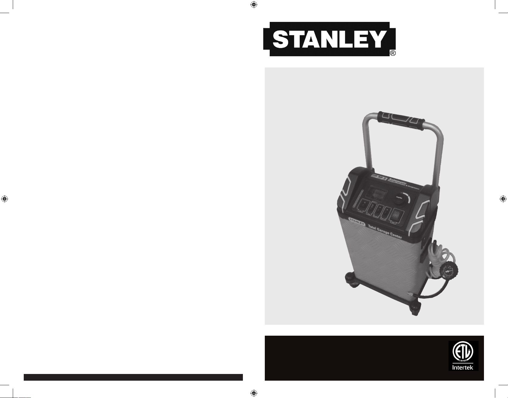
ToTal GaraGe CenTer
InsTruCTIon Manual
CenTro ToTal del GaraGe
Manual de InsTruCCIón
English page 4
Español pagina 14
SAVE THIS INSTUCTION MANUAL FOR FUTURE REFERENCE.
CONSERVE ESTE MANUAL PARA FUTURAS CONSULTAS.
© 2011 Baccus Global
Boca Raton, FL 33432
Customer Service: (877) 571-2391
TGC11_ManualENSP_051211.indd 24-1 5/12/2011 11:05:00 PM
124
Page 2
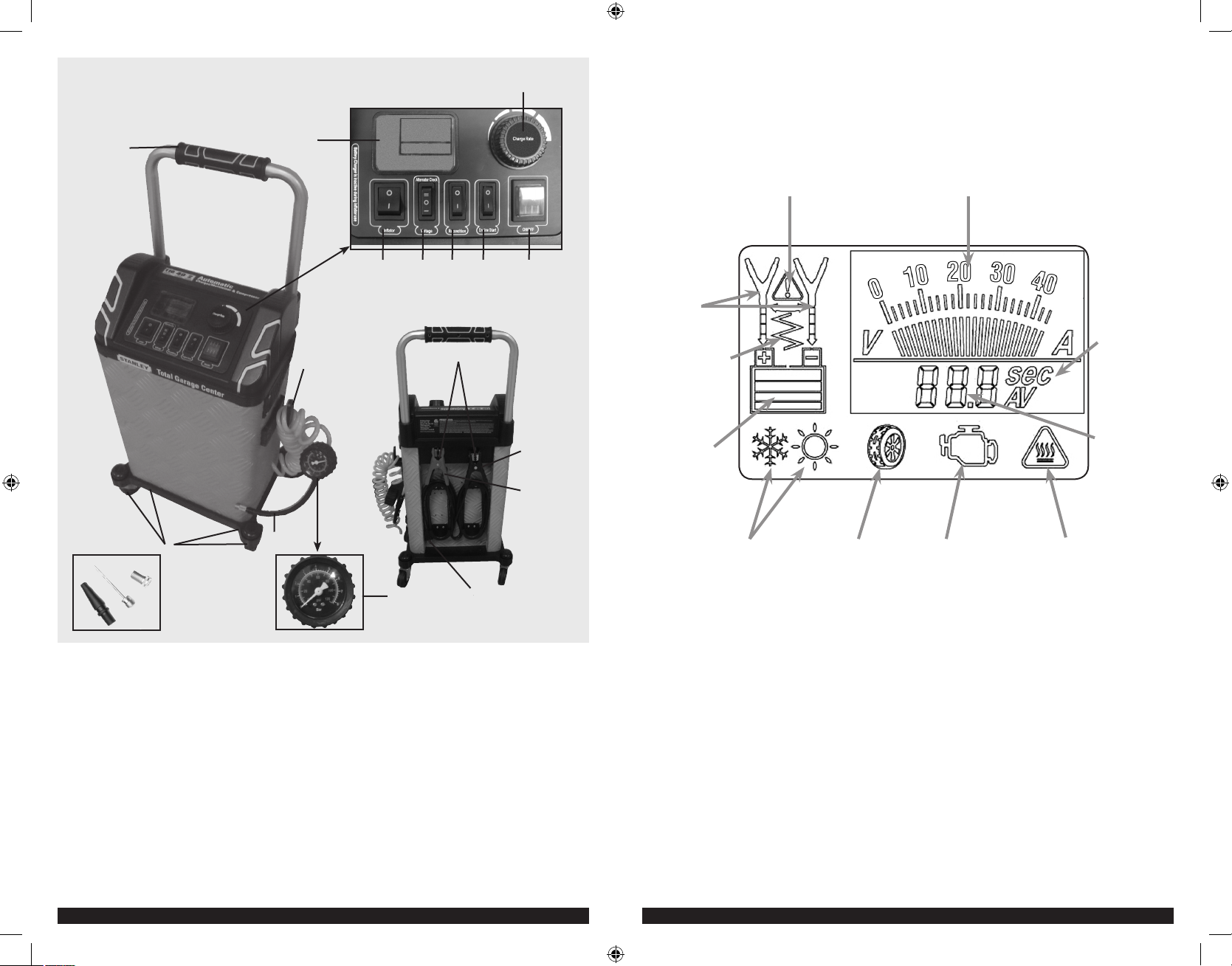
FEATURES
4
DIGITAL LCD SCREEN
CARACTERÍSTICAS
2
1
17
PANTALLA DEL LCD DIGITAL
3
Alarm icon
Icono de la alarma
9 8
10
16
16
7 6 5
11
12
13
14
Clamp icons
Iconos de la
pinzas
Battery recondition
icon
Icono de la
reacondicionamiento
de la batería
Battery capacity
icon
Icono de la
capacidad de la
batería
Surrounding
temperature icons
Iconos de
temperatura
circundantes
Inflator mode icon
Icono de modo de la
inflador
Voltage/current gage
Calibrador del voltaje y de la corriente
Pump engine icon
Icono del motor del
comienzo
Overheat alarm icon
Icono de la alarma del
sobrecalentamiento
Seconds/amperes/
voltage indicator
Indicador de los
segundos/
amperios/voltaje
Digital Display
(varies by
function)
Indicador
digital (varía
dependiendo de
la función)
FEATURES
1. Wheels
2. Grip handle (detachable)
3. Digital LCD screen
4. Output current adjustment knob
5. Main power on/off switch
6. Engine start switch
7. Battery recondition switch
8. Alternator check/battery voltage check toggle switch
9. Inflator power switch
10. Air hose storage hook
11. Battery clamp tabs
12. Negative (black) clamp
13. Positive (red) clamp
14. 120 volt AC plug
15. Air pressure gage
16. Air hose
17. Adapter nozzles
TGC11_ManualENSP_051211.indd 2-3 5/12/2011 11:05:01 PM
CARACTERÍSTICAS
1. Ruedas
3. Agarradera (desmontable)
3. Pantalla del LCD digital
4. Perilla para ajustar la corriente de salida
5. Interruptor de encendido principal
6. Botón de comienzo del motor
7. Interruptor de la reacondicionamiento de la batería
8. Interruptor eléctrico para la verificación del cheque del alternador
y de voltaje de la batería
9. Interruptor del inflador
10. Gancho del almacenaje de la manguera de aire
11. Lengüetas para sostener las abrazaderas de la batería
12. Pinza del negativo (negra)
13. Pinza del positivo (roja)
14. Enchufe de la CA de 120 voltios
15. Galga de presión
16. Manguera de aire
17. Picos del adaptador
32
Page 3
This device complies with part 15 of the FCC rules. Operation is subject to the following two conditions: (1) this device may not
cause harmful interference, and (2) this device must accept any interference received, including interference that may cause
undesired operation.
This equipment has been tested and found to comply with the limits for a Class B digital device, pursuant to part 15 of the
FCC Rules. These limits are designed to provide reasonable protection against harmful interference in a residential installation.
This equipment generates, uses and can radiate radio frequency energy and, if not installed and used in accordance with the
instructions, may cause harmful interference to radio communications. However, there is no guarantee that interference will
not occur in a particular installation. If equipment does cause harmful interference to radio or television reception, which can
be determined by turning the equipment off and on, the user is encouraged to try to correct the interference by one or more of
the following measures:
• Reorient or relocate the receiving antenna.
• Increase the separation between equipment and receiver.
• Connect the equipment into an outlet on a circuit different from that to which the receiver is connected.
• Consult the dealer or an experienced radio/TV technician for help.
Changes or modifications not approved by the party responsible for compliance could void user’s authority to operate the
equipment.
GENERAL SAFETY WARNINGS AND INSTRUCTIONS
READ ALL INSTRUCTIONS
WARNING: Read all instructions before operating battery charger. Failure to follow all instructions listed below may
result in electric shock, fire and/or serious injury.
SAFETY GUIDELINES / DEFINITIONS
DANGER: Indicates an imminently hazardous situation which, if not avoided, will result in death or serious injury.
WARNING: Indicates a potentially hazardous situation which, if not avoided, could result in death or serious injury.
CAUTION: Indicates a potentially hazardous situation which, if not avoided, may result in minor or moderate injury.
CAUTION: Used without the safety alert symbol indicates potentially hazardous situation which, if not avoided, may result in
property damage.
RISK OF UNSAFE OPERATION. When using tools or equipment, basic safety precautions should always be followed to reduce the
risk of personal injury. Improper operation, maintenance or modification of tools or equipment could result in serious injury and
property damage. There are certain applications for which tools and equipment are designed. Manufacturer strongly recommends
that this product NOT be modified and/or used for any application other than for which it was designed. Read and understand all
warnings and operating instructions before using any tool or equipment.
Recommended Minimum AWG Size for Extension Cords for Battery Chargers
AC Input Rating American Wire Gage (AWG) Size of Cord
Amperes Length of Cord, feet (m)
Equal to or But less
greater than than
0 2 18 18 18 16
2 3 18 18 16 14
3 4 18 18 16 14
4 5 18 18 14 12
5 6 18 16 14 12
6 8 18 16 12 10
8 10 18 14 12 10
10 12 16 14 10 8
12 14 16 12 10 8
14 16 16 12 10 8
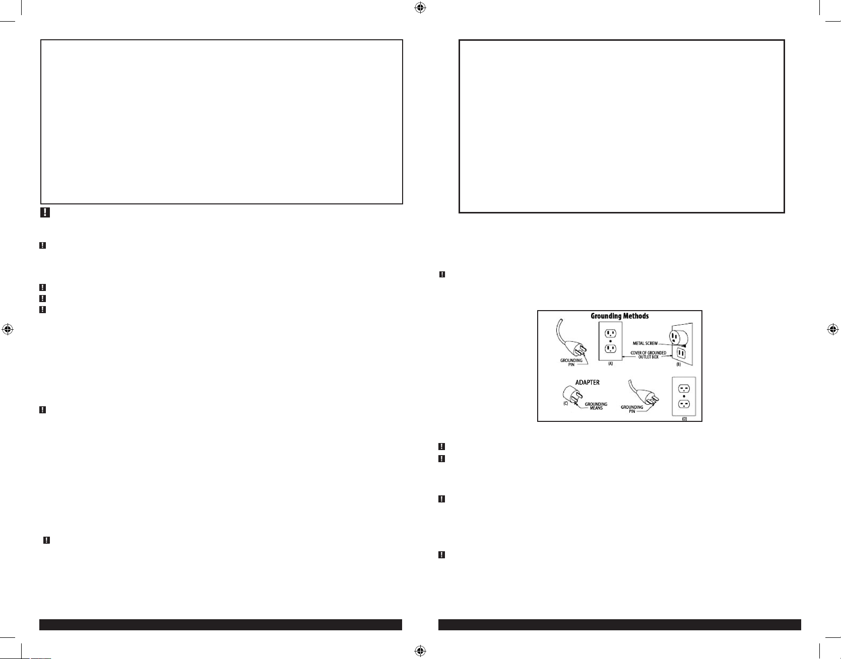
Power Cord Safety
This unit is intended for use on a nominal 120-volt circuit, and has a grounding plug that looks like the plug illustrated in the
sketch A in the illustration below. A temporary adapter, which looks like the adapter illustrated in sketches B and C, may be used
to connect this plug to a two-pole receptacle as shown in sketch B if a properly grounded outlet is not available. The temporary
adapter should be used only until a properly grounded outlet can be installed by a qualified electrician.
ear or lug extending from adapter must be connected to a properly grounded outlet– make certain it is grounded. If necessary,
replace original outlet cover plate screw with a longer screw that will secure adapter ear or lug to outlet cover plate and make
ground connection to grounded outlet.
16 18 14 12 8 8
18 20 14 12 8 6
DANGER: Before using adapter as illustrated, be certain that center screw of outlet plate is grounded. The green-colored rigid
25 (7.6) 50 (15.2) 100 (30.5) 150 (45.6)
IMPORTANT SAFETY INSTRUCTIONS
WARNING: This product or its power cord contains lead, a chemical known to the State of California to cause cancer and birth
defect or other reproductive harm. Wash hands after handling.
• Avoid dangerous environments. Don’t use battery chargers in damp or wet locations.
• Keep children away. Keep away from children. This is not a toy!
• Store indoors. When not in use, battery chargers should be stored indoors in dry, and high or locked-up places – out of reach of
children.
• Unplug the battery charger when not in use.
SPECIFIC SAFETY INSTRUCTIONS FOR POWER CORDS
• Don’t abuse cord. Never carry appliance by cord or yank it to disconnect from receptacle. Keep cord from heat, oil, and sharp
edges. Pull cord by plug rather than cord when unplugging the unit.
• Ground Fault Circuit Interrupter (GFCI) protection should be provided on the circuits or outlets to be used. Receptacles are
available having built in GFCI protection and may be used for this measure of safety.
• Extension cords:
WARNING: An extension cord should not be used unless absolutely necessary. Use of improper extension cord could result in a
risk of fire and electric shock. If an extension cord is used, make sure that the pins of the extension cord are the same number, size
and shape as those in the charger.
Make sure your extension cord is in good condition. When using an extension cord, be sure to use one heavy enough to carry the
current your product will draw. An undersized cord will cause a drop in line voltage resulting in loss of power and overheating. The
following table shows the correct size to use depending on cord length and nameplate ampere rating. If in doubt, use the next
heavier gage. The smaller the gage number, the heavier the cord.
TGC11_ManualENSP_051211.indd 4-5 5/12/2011 11:05:01 PM
SPECIFIC SAFETY INSTRUCTIONS FOR INFLATORS
CAUTION: TO REDUCE THE RISK OF INJURY OR PROPERTY DAMAGE: Never leave the inflator unattended while in use.
WARNING: BURST HAZARD:
• Carefully follow instructions on articles to be inflated.
• Never exceed recommended pressures. Bursting articles can cause serious injury.
• Always check pressure with the pressure gage.
CAUTION: TO REDUCE THE RISK OF PROPERTY DAMAGE:
Do not operate inflator continuously for longer than approximately 10 minutes, depending on ambient temperatures, as it may
overheat. In such event, inflator may automatically shut down. Turn off the Inflator Power Switch immediately and restart after a
cooling down period of approximately 30 minutes.
SPECIFIC SAFETY INSTRUCTIONS FOR BATTERY CHARGERS
WARNING: BURST HAZARD: Do not use the unit for charging dry-cell batteries that are commonly used with home appliances.
These batteries may burst and cause injury to persons and damage property. Use the unit for charging/boosting a 12 volt LEADACID battery only. It is not intended to supply power to a low-voltage electrical system other than in a starter-motor application.
• This unit was designed for household use only.
• Use of accessories and attachments: The use of any accessory or attachment not recommended by manufacturer for use with
this battery charger could be hazardous.
54
Page 4
• Stay alert. Use common sense. Do not operate battery charger when you are tired.
• Check for damaged parts. Any part that is damaged should be properly repaired or replaced by an authorized service center
unless otherwise indicated elsewhere in this instruction manual before further use.
• Do not operate the battery charger near flammable liquids or in gaseous or explosive atmospheres. Motors may spark, and the
sparks might ignite fumes.
WARNING: TO REDUCE THE RISK OF ELECTRIC SHOCK:
• Never immerse the battery charger in water or any other liquid, or use when wet.
WARNING: RISK OF EXPLOSIVE GASES:
• Working in the vicinity of a lead acid battery is dangerous. Batteries generate explosive gases during normal battery operation.
For this reason, it is of the utmost importance that each time before using the battery maintainer you read this manual and follow
instructions exactly.
• To reduce the risk of battery explosion, follow these instructions and those published by the battery manufacturer and
manufacturer of any equipment you intend to use in the vicinity of the battery. Review cautionary markings on these products
and on the engine.
• THIS UNIT IS NOT FOR USE BY CHILDREN AND SHOULD ONLY BE OPERATED BY ADULTS.
WARNING: TO REDUCE THE RISK OF SERIOUS ELEC TRICAL DAMAGE AND/OR A FIRE:
• Do not operate near flammable materials, fumes or gases.
• Do not expose to extreme heat or flames.
CAUTION: TO REDUCE THE RISK OF INJURY OR PROPERTY DAMAGE:
• NEVER ATTEMPT TO JUMP-START OR CHARGE A FROZEN BATTERY.
• Do not charge the battery while the engine is operating.
• Use the unit on a flat, level surface to avoid movement during operation. If it must be used on a slanting or uneven surface, take
proper precautions to secure the wheels to avoid shifting or movement before use.
• Stay clear of fan blades, belts, pulleys, and other parts that can cause injury to persons.
• Vehicles that have on-board computerized systems may be damaged if vehicle battery is started using the engine start function.
Before attempting to use this function, read the vehicle’s owner’s manual to confirm that external-starting assistance is suitable.
• When working with lead acid batteries, always make sure immediate assistance is available in case of accident or emergency.
• Always have protective eyewear when using this product: contact with battery acid may cause blindness and/or severe burns. Be
aware of first aid procedures in case of accidental contact with battery acid.
• Have plenty of fresh water and soap nearby in case battery acid contacts skin.
• If battery acid contacts skin or clothing, wash immediately with soap and water for at least 10 minutes and get medical attention
immediately.
• Never smoke or allow a spark or flame in vicinity of vehicle battery, engine or battery charger.
• Remove personal metal items such as rings, bracelets, necklaces and watches when working with a lead acid battery. A lead acid
battery can produce a short circuit current high enough to weld a ring, or similar metal object, to skin causing a severe burn.
• Never allow battery acid to come in contact with this unit.
• Do not operate this unit in a closed area or restrict ventilation in any way.
• Always turn the battery charger off by unplugging it when not in use.
• DO NOT OPEN THE BATTERY CHARGER — there are no user-serviceable parts inside. Opening the battery charger will void
manufacturer’s warranty.
• Operate battery charger only as described in this Instruction Manual.
• Check battery charger and components periodically for wear and tear. Return to manufacturer for replacement of worn or
defective parts immediately.
Connection Precautions
• Connect and disconnect output clamps or vehicle accessory plug only after removing AC cord from electric outlet.
• Never allow clamps to touch each other.
• Attach clamps only as indicated in “Charging the Battery.”
• FIRST AID – SKIN: If battery acid comes in contact with skin, rinse immediately with water, then wash thoroughly with soap and
water. If redness, pain, or irritation occurs, seek immediate medical attention.
EYES: If battery acid comes in contact with eyes, flush eyes immediately, for a minimum of 15 minutes and seek immediate
medical attention.
LCD LIQUID CRYSTAL DISPLAY: If liquid crystal comes in contact with your skin: Wash area off completely with plenty of water.
Remove contaminated clothing. If liquid crystal gets into your eye: Flush the affected eye with clean water and then seek medical
attention. If liquid crystal is swallowed: Flush your mouth thoroughly with water. Drink large quantities of water and induce
vomiting. Then seek medical attention.
WARNING: TO REDUCE THE RISK OF INJURY OR PROPERTY DAMAGE: Follow these instructions and those published
by the manufacturer of any engine you intend to use with this battery charger. Review cautionary markings on the battery charger
and engine.
INTRODUCTION
Congratulations on purchasing your new Total Garage Center. Read this Instruction Manual and follow the instructions
carefully before using your new battery charger.
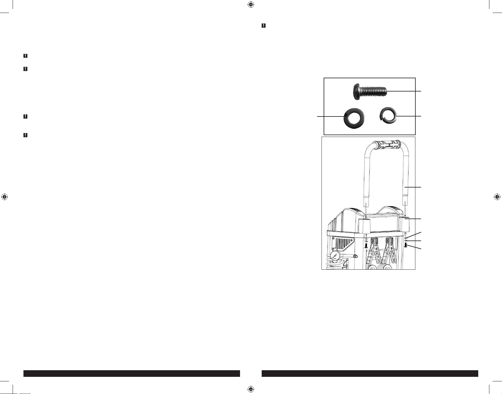
ASSEMBLY INSTRUCTIONS
Handle Parts
Handle screW
(2 pieces)
Handle WasHer
(2 pieces)
Handle Installation
1. Place the handle into the top of the handle slot as shown.
2. Align one screw set (handle screw, the handle spring washer and handle washer – in the sequence shown in the illustration)
for each side of the handle. Screw each screw set into a corresponding handle slot. Do not over-tighten.
Handle spring WasHer
(2 pieces)
Handle
Handle slot
Handle spring WasHer
Handle WasHer
Handle screW
SAVE THESE INSTRUCTIONS
6 7
TGC11_ManualENSP_051211.indd 6-7 5/12/2011 11:05:02 PM
Page 5

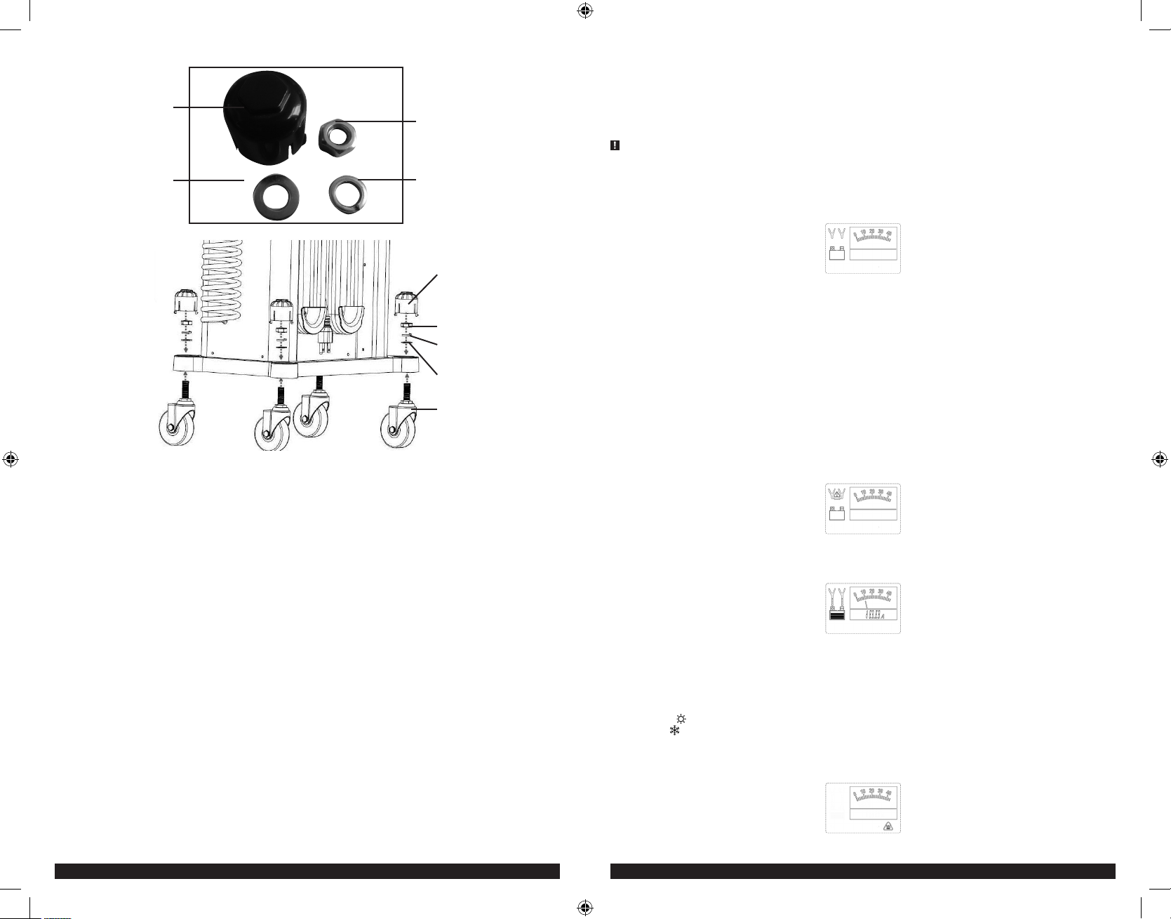
Wheel Parts
WHeel cover
(4 pieces)
WHeel WasHer
(4 pieces)
Hexagon WHeel nut
(4 pieces)
WHeel spring WasHer
(4 pieces)
WHeel cover
Hexagon WHeel nut
WHeel spring WasHer
WHeel WasHer
WHeel
Wheel Installation
1. Align the wheels to the holes in the base on each corner of the bottom frame of the unit.
2. Screw one hexagon wheel nut, wheel spring washer and wheel washer through the base hole and down into each wheel’s
screw post.
3. Snap the wheel cover into the base hole over each wheel screw assembly.
OPERATING INSTRUCTIONS
Using More Than One Function
When the unit is charging a battery, only one additional function (battery voltage check, alternator check, battery recondition
or engine start) can be performed, with the exception of the inflator function; and the user must manually turn off one function
before turning on another.
IMPORTANT: The inflator function takes precedence over any other functions that may be operating. When the inflator power
switch is pressed to on (
Preparing to Charge
1. Remove battery completely from boat/airplane or any confined area before charging.
2. If it is necessary to remove battery from vehicle to charge, or to clean terminals, always remove grounded terminal from battery
first. Make sure all accessories in the vehicle are off, so as not to cause an arc.
3. Clean battery terminals, taking care to avoid getting corrosive material in eyes.
4. Add distilled water in each cell until battery acid reaches level specified by battery manufacturer. This helps purge excessive
gas from cells. Do not overfill. For a battery without cell caps (maintenance free), carefully follow manufacturer’s charging
instructions.
5. Study all battery manufacturer’s specific precautions, such as removing or not removing cell caps while charging, and
recommended rates of charge.
Charger Location
• Locate charger as far away from battery as cables permit.
• Never place charger directly above battery being charged; gases from battery will corrode and damage charger.
I
), all other functions will be inactive.
• Never allow battery acid to drip on charger.
• Never operate charger in a closed-in area or restrict ventilation in any way.
• Marine batteries must be removed and charged on shore.
• Do not set a battery on top of charger.
• Use the unit on a flat, level surface to avoid movement during operation. If it must be used on a slanting or uneven surface, take
proper precautions to secure the wheels to avoid shifting or movement before use.
Charging the Battery
WARNING: A SPARK NEAR THE BATTERY MAY CAUSE AN EXPLOSION. To reduce the risk of a spark near the battery
position AC cord away from hood, door, or moving engine parts.
1. Plug the battery charger’s power cord into an AC outlet. The main power on/off switch will light red when the unit is properly
connected.
2. Press the main power on/off switch to turn the unit on. A beep will sound, the power on/off switch will light red and the LCD
screen will display the following:
The clamp icons will flash to indicate the battery clamps are not yet connected to the battery.
3. Check polarity of battery posts. Positive (POS, P, +) battery post usually has larger diameter than negative (NEG, N, –) post.
4. Determine which post of battery is grounded (connected) to the chassis. If negative post is grounded to chassis (as in most
vehicles), see 5. If positive post is grounded to the chassis, see 6.
5. For negative-grounded vehicle, connect positive (red) clamp from battery charger to positive (POS, P, +) ungrounded post of
battery. Connect negative (black) clamp to vehicle chassis or engine block away from battery. Do not connect clip to carburetor,
fuel lines, or sheet-metal body parts. Connect to heavy gage metal part of the frame or engine block.
6. For positive-grounded vehicle, connect negative (black) clamp from battery charger to negative (NEG, N, –) ungrounded post
of battery. Connect positive (red) clamp to vehicle chassis or engine block away from battery. Do-not connect clip to carburetor,
fuel lines or sheet-metal body parts. Connect to a heavy gage metal part of the frame or engine block.
IMPORTANT: If the clamps are INCORRECTLY connected with regard to polarity, the LCD screen will display the following (the
alarm icon in the triangle and the curved arrow will flash) until the clamps are disconnected:
Unplug the charger; then remove the clamps. Reconnect the clamps properly.
7. If the clamps are CORRECTLY connected with regard to polarity and the unit is properly connected to the AC outlet, a beep will
sound and the unit will AUTOMATICALLY begin charging the battery. The LCD screen will display the following:
The digital display shows the output current that is charging the battery. The bars on the battery icon will change from empty
to solid (bottom to top) repeatedly and the arrows pointing to the “+” and “–” flash.
To change the output charging current, simply turn the output current adjustment knob. The digital display will reflect the value selected. The
Notes:
maximum output current is 40A.
If the battery is already charged to nearly full capacity, the unit’s output current may be reduced by a few amperes, despite the 40A user setting.
The
icon will appear at the bottom left of the digital display if the surrounding ambient temperature is higher than approximately 40°C. The
icon will appear at the bottom left of the digital display if the surrounding ambient temperature is lower than 0°C. This is not a fault code, but
indicates that the unit’s temperature compensation feature is operating.
IMPORTANT:
If the battery is overheated, the charging process will terminate and the LCD screen will display the flashing overheat alarm
icon, as follows:
Disconnect the charger and allow the charger to cool for several minutes. Make sure there is adequate ventilation around the
unit before attempting to charge again.
8 9
TGC11_ManualENSP_051211.indd 8-9 5/12/2011 11:05:02 PM
Page 6

If the charger detects a problem with the battery, the LCD screen will display the following to indicate a fault condition (the
clamp icon will light and the empty battery icon will flash):
Disconnect the charger. Have the battery checked by a qualified technician.
8. When the charging is complete, the arrow and clamp icons stop displaying. The digital display shows “0A.” The battery fully
charged icon will display on the LCD screen:
When disconnecting charger, disconnect AC cord, remove clamp from vehicle chassis, and then remove clamp from battery
terminal.
Checking the Battery Voltage
1. Set up the battery charger and connect to the battery following steps 1 through 7 in the “Charging the Battery” section.
2. Press the alternator check/battery voltage check toggle switch to the voltage position (–) to start the check. A beep will sound
and the LCD screen will display the following:
Part 2
Under Load (accessories ON): Next, load the alternator by turning on as many accessories as possible (except for A/C and Defrost).
1. Press the alternator check/battery voltage check toggle switch to the alternator check position (=) to start the check. The LCD
screen will display the following to indicate the unit is analyzing the alternator:
The pump engine icon and the half-full battery icon will flash.
2. If the unit detects that the alternator is good, the LCD screen will display the following:
The pump engine icon will light solid, and the bars on the battery icon will change from empty to solid (bottom to top)
repeatedly.
3. If the unit detects that the alternator is out of typical voltage range, the LCD screen will display the following:
The digital display shows the current voltage of the connected battery.
To end this function, press the alternator check/battery voltage check toggle switch to the off position (O). When disconnecting
charger, disconnect AC cord, remove clamp from vehicle chassis, and then remove clamp from battery terminal.
Using the Alternator Check Function
Set up the battery charger and connect to the battery following steps 1 through 7 in the “Charging the Battery” section.
Part 1
No Load (turn OFF all vehicle’s accessories): The battery must be fully charged before testing the alternator. Run the engine long
enough to achieve normal idle speed and verify there is a no-load voltage.
1. Press the alternator check/battery voltage check toggle switch to the alternator check position (=) to start the check. The LCD
screen will display the following to indicate the unit is analyzing the alternator:
The pump engine icon and the half-full battery icon will flash.
2. If the unit detects that the alternator is good, the LCD screen will display the following:
The pump engine icon will light solid, and the bars on the battery icon will change from empty to solid (bottom to top)
repeatedly.
3. If the unit detects that the alternator is out of typical voltage range, the LCD screen will display the following:
The half-full battery icon will light solid and the triangular alarm icon will flash.
4. Press the alternator check/battery voltage check toggle switch to the off posiiton (O) to stop the test.
The half-full battery icon will light solid and the triangular alarm icon will flash.
4. Press the alternator check/battery voltage check toggle switch to the off posiiton (O) to stop the test.
The unit may detect that the alternator is out of typical voltage range because someone has added a number of accessory loads on the charging system,
Notes:
thereby increasing current demand from the alternator. MAKE SURE THAT THE ALTERNATOR IS RATED TO SUPPORT THE APPLICATION.
This check may not be accurate for every make, manufacturer and model of vehicle. Check only 12 volt systems.
When disconnecting the charger, disconnect AC cord, remove clamp from vehicle chassis, and then remove clamp from battery terminal.
Reconditioning the Battery
Periodic reconditioning is recommended to maintain a battery's optimum performance. Battery recondition sends a series of
electrical pulses to break up the crystalline form of lead sulfate and turn these chemicals into useful battery electrolytes.
1. Set up the battery charger and connect to the battery following steps 1 through 7 in the “Charging the Battery” section.
2. Press the battery recondition switch to turn this function on (I). A beep will sound and the LCD screen will display the following:
The digital display stops displaying and the battery recondition icon will flash. The bars on the battery icon will change from
solid to empty (top to bottom) repeatedly, the pump engine icon displays and the arrows pointing to the “+” and “–” flash.
The process will stop automatically after 24 hours. To stop the process sooner, press the battery recondition switch to turn it off (O).
The unit will revert to charging mode. To end the charging process, turn the unit off using the main on/off switch.
More than 24 hours may be needed to restore performance on some batteries. If so, repeat the process.
IMPORTANT: If 5 cycles of reconditioning does not improve battery performance, discontinue and recycle the battery.
When disconnecting charger, disconnect AC cord, remove clamp from vehicle chassis, and then remove clamp from battery
terminal.
Using the Engine Start Function
1. Set up the battery charger and connect to the battery following steps 1 through 7 in the “Charging the Battery” section.
I
2. Press the engine start button to turn this function on (
). A beep will sound and the LCD screen will display the following:
The bars on the battery icon will change from empty to solid (bottom to top) repeatedly, the pump engine icon displays, and
the arrows pointing to “+” and “–” flash. The digital display shows the countdown from “90” to “0” seconds.
To stop the process, press the engine start switch to turn it off (O). The unit will revert to charging mode.
Note:
10 11
TGC11_ManualENSP_051211.indd 10-11 5/12/2011 11:05:03 PM
Page 7

3. When “0” is reached, the LCD screen will display the following; and the vehicle is ready to start.
4. Crank the engine using manufacturer’s guidelines, typically in 3 to 5 second bursts. The function requires a resting/cooling
period between attempts. Wait 4 to 5 minutes before a second attempt at starting the engine, if needed.
5. To stop the process, press the engine start switch to turn it off (O). The unit will revert to charging mode. To end the charging
process, turn the unit off using the main on/off switch.
When disconnecting charger, disconnect AC cord, remove clamp from vehicle chassis, and then remove clamp from battery
terminal.
CAUTION: TO REDUCE THE RISK OF PROPERTY DAMAGE:
• Vehicles that have on-board computerized systems may be damaged if vehicle battery is started using the engine start function.
Before attempting to use this function, read the vehicle’s owner’s manual to confirm that external-starting assistance is suitable.
• Excessive engine cranking can damage the vehicle‘s starter motor. If the engine fails to start after the number of attempts
recommended by battery manufacturer, discontinue the procedure and contact a qualified technician to investigate why the
engine did not start.
Using the Portable Inflator
The built-in inflator is the ultimate inflator for most vehicle tires, trailer tires and recreational inflatables. The inflator hose with
tire fitting is stored on the right side of the unit. The air pressure gage is located in the front of the inflator hose. The inflator power
switch is located on the bottom left of the control panel.
The inflator may be used by removing the air hose from the storage hatch and if required, fitting an appropriate nozzle to the air
hose. Return hose to the storage hook after use.
InflatIng tIres or Products WIth ValVe stems
1. Screw the SureFit™ nozzle connector into the valve stem. Do not overtighten.
2. Plug the battery charger’s power cord into an AC outlet and press the main power on/off switch to turn the unit on.
3. Turn on the inflator power switch (I). The LCD screen will display the following flashing inflator mode icon:
4. Check pressure with the pressure gage.
5. Turn off the inflator power switch (O).
6. When desired pressure is reached, unscrew the SureFit™ nozzle connector from the valve stem.
The unit will revert to charging mode if the unit is connected to the battery. To end the charging process, turn the unit off using the main on/off
Note:
switch. When disconnecting charger, disconnect AC cord, remove clamp from vehicle chassis, and then remove clamp from batter y terminal.
7. Allow unit to cool before storing away.
8. Store inflator hose and tire fitting on the storage hook on the side of the unit.
InflatIng other Inflatables WIthout ValVe stems
Inflation of other items requires use of one of the adapters (nozzles).
1. Select the appropriate adapter nozzle.
2. Screw the adapter (i.e. needle) into the Surefit™ nozzle connector. Do not overtighten.
3. Insert adapter (i.e., needle) into item to be inflated.
4. Turn on the inflator power switch (I) and inflate to desired pressure or fullness.
IMPORTANT NOTE: Small items such as volleyballs, footballs, etc. inflate very rapidly. Do not over-inflate.
5. Switch the inflator power switch off (O).
6. Remove adapter.
The unit will revert to charging mode if the unit is connected to the battery. To end the charging process, turn the unit off using the main on/off
Note:
switch. When disconnecting charger, disconnect AC cord, remove clamp from vehicle chassis, and then remove clamp from batter y terminal.
7. Allow unit to cool before storing away.
8. Store inflator hose and tire fitting on the storage hook on the side of the unit.
WARNING: TO REDUCE THE RISK OF INJURY OR PROPERTY DAMAGE: FOLLOW ALL SAFET Y INSTRUCTIONS FOUND IN
THE “SPECIFIC SAFETY INSTRUC TIONS FOR INFLATORS” SEC TION OF THIS INSTRUCTION MANUAL.
TROUBLESHOOTING
Unit Fails to Charge Battery
• Check that the charger is properly connected to a live 120 volt AC outlet.
• If the battery to be charged has fallen below 2 volts, the battery cannot be recharged with this charger.
Engine Start Fails to Start Engine
• Check that the charger is properly connected to a live 120 volt AC outlet.
• Make sure unit’s engine start switch is in the on position.
• Make sure a proper polarity cable connection has been established.
Portable Inflator will not inflate
• Make sure the inflator power switch is in the on position.
• Make sure the SureFit™ nozzle connector is securely screwed into the valve stem when attempting to inflate tires; or nozzle
(adapter) is securely inserted into connector (chuck) on all other inflatables.
CARE AND MAINTENANCE
Storage
• Store the unit in a clean, dry, cool place when not in use.
• Clean the unit casing and cords (as necessary) with a dry (or slightly damp) cloth. Ensure that unit is completely disconnected
from battery and power source before cleaning.
• To maintain the operating condition and maximize the life of the charger cords, always coil them loosely for storage. Do not wrap
them around the unit or crimp them with a tight band.
ACCESSORIES
Recommended accessories for use with your tool are available from your local dealer or authorized service center. If you need
assistance regarding accessories, please contact manufacturer at (877) 571-2391.
WARNING: The use of any accessory not recommended for use with this appliance could be hazardous.
SERVICE INFORMATION
Whether you need technical advice, repair, or genuine factory replacement parts, contact the manufacturer at (877) 571-2391.
ONE YEAR LIMITED WARRANTY
The manufacturer warrants this product against defects in materials and workmanship for a period of ONE (1) YEAR from the date
of retail purchase by the original end-user purchaser (“Warranty Period”).
If there is a defect and a valid claim is received within the Warranty Period, the defective product can be replaced or repaired in
the following ways: (1) Return the product to the retailer where product was purchased for an exchange (provided that the store
is a participating retailer). Returns to retailer should be made within the time period of the retailer’s return policy for exchanges
only (usually 30 to 90 days after the sale). Proof of purchase may be required. Please check with the retailer for their specific return
policy regarding returns that are beyond the time set for exchanges. (2) Return the product to the manufacturer for repair or
replacement at manufacturer’s option. Proof of purchase may be required by manufacturer.
This warranty does not apply to accessories, bulbs, fuses and batteries; defects resulting from normal wear and tear, accidents;
damages sustained during shipping; alterations; unauthorized use or repair; neglect, misuse, abuse; and failure to follow
instructions for care and maintenance for the product.
This warranty gives you, the original retail purchaser, specific legal rights and you may have other rights which vary from state to
state or province to province. This product is not intended for commercial use.
Please complete the Product Registration Card and return within 30 days from purchase of the product to: Baccus Global LLC, 595 S.
Federal Highway, Suite 210, Boca Raton, FL 33432. Baccus Global LLC, toll-free number: 1-877-571-2391.
SPECIFICATIONS
Input: 120VAC, 60Hz, 9.5A
Output: 12VDC, 40A
Inflator Maximum Pressure: 120 PSI
Imported by
Baccus Global
399 NW 2nd Avenue, Suite 150,
Boca Raton, FL 33432
(877) 571-2391
1500W engine start
110A engine start (5 minutes off; 5 seconds on)
RD051211
12 13
TGC11_ManualENSP_051211.indd 12-13 5/12/2011 11:05:03 PM
Page 8

Este dispositivo cumple con la parte 15 de las normas de la Comisión Federal de Comunicaciones de Estados Unidos (FCC).
La operación está sujeta a las dos condiciones siguientes: (1) este dispositivo no puede causar interferencia perjudicial y (2)
este mecanismo debe aceptar cualquier interferencia recibida, incluida la in-terferencia que puede provocar una operación no
deseada.
Este equipo ha sido probado y se encontró que cumple con los límites para dispositivo digital Clase B, según la parte 15 de
las normas de la FCC. Estos límites están diseñados para brindar protección razonable contra interferencia perjudicial en una
instalación residencial. Este equipo genera, usa y puede irradiar energía en frecuencia de radio y, si no se instala y se usa de
acuerdo con las instrucciones, puede provocar interferencia perjudicial en las comunicaciones de radio. Sin embargo, no hay
garantía de que la interferencia no ocurra en una instalación en particular. Si el equipo provoca interferencia perjudicial en la
recepción de radio o televisión, lo que se puede determinar al apagar y encender el equipo, el usuario debe tratar de corregir
la interferencia mediante una o más de las siguientes medidas:
• Cambiar la orientación o la ubicación de la antena de recepción.
• Aumentar la separación entre el equipo y el receptor.
• Conectar el equipo a un tomacorriente sobre un circuito diferente de aquel al que está conectado el receptor.
• Consultar al vendedor o pedir la ayuda de un técnico en radio y televisión con experiencia.
Los cambios o las modificaciones no aprobados por el partido responsable de conformidad podían anular la autoridad del
usuario para funcionar el equipo.
ADVERTENCIAS E INSTRUCCIONES DE SEGURIDAD GENERALES
LEA LAS INSTRUCCIONES
ADVERTENCIA: Lea todas las instrucciones antes de operar el cargador de batería. El incumplimiento de todas las
instrucciones enumeradas a continuación puede provocar una descarga eléctrica, un incendio o lesiones graves.
NORMAS DE SEGURIDAD / DEFINICIONES
PELIGRO: Indica una situación de peligro inminente que, si no se evita, provocará la muerte o lesiones graves.
ADVERTENCIA: Indica una situación de peligro inminente que, si no se evita, provocará la muerte o lesiones graves.
PRECAUCIÓN: Indica una situación de peligro potencial que, si no se evita, puede provocar lesiones leves o moderadas.
PRECAUCIÓN: Utilizado sin el símbolo de alerta de seguridad indica una situación de peligro potencial que, si no se evita, puede
provocar daños en la propiedad.
RIESGO DE OPERACIÓN INSEGURA. Cuando se utilizan herramientas o equipos, siempre se deben respetar las precauciones
de seguridad para reducir el riesgo de lesiones personales. La operación, el mantenimiento o la modificación incorrectos de
herramientas o equipos pueden provocar lesiones graves y daños a la propiedad. Las herramientas y los equipos están diseñados
para determinados usos. Fabricante recomienda encarecidamente que NO se modifique este producto y que NO se utilice para
ningún otro uso que aquél para el que fue diseñado. Lea y comprenda todas las instrucciones operativas y las advertencias antes de
utilizar cualquier herramienta o equipo.
Asegúrese de que el cable prolongador esté en buenas condiciones. Cuando utilice un cable prolongador, asegúrese de que tenga
la capacidad para conducir la corriente que su producto exige. Un cable de menor capacidad provocará una disminución en el
voltaje de la línea, lo cual producirá una pérdida de potencia y sobrecalentamiento. La siguiente tabla muestra la medida correcta
que debe utilizar según la longitud del cable y la capacidad nominal en amperios indicada en la placa. En caso de duda, utilice el
calibre inmediatamente superior. Cuanto menor es el número de calibre, más grueso es el cable.
Tamaño mínimo recomendado del AWG para las cuerdas de extensión para los cargadores de batería
Grado de la entrada de la CA Tamaño de las normas americanas de cableado (AWG) de la cuerda
Amperios Longitud de la cuerda, pies (m)
Igual a o Pero menos
mayor que que
0 2 18 18 18 16
2 3 18 18 16 14
3 4 18 18 16 14
4 5 18 18 14 12
5 6 18 16 14 12
6 8 18 16 12 10
8 10 18 14 12 10
10 12 16 14 10 8
12 14 16 12 10 8
14 16 16 12 10 8
16 18 14 12 8 8
18 20 14 12 8 6
25 (7.6) 50 (15.2) 100 (30.5) 150 (45.6)
Seguridad del cable eléctrico
Esta unidad se piensa para el uso en un nominal circuito de 120 voltios, y tiene un enchufe que pone a tierra que parezca el enchufe
ilustrado en el bosquejo A en la ilustración abajo.
PELIGRO: Antes de usar el adaptador como ilustrado, estar seguro lo que centra el tornillo del plato de salida es basado. El oído
rígido verde coloreado o arrastra la ampliación del adaptador debe estar relacionado con una salida correctamente basada – hacen
seguro es basado. Si es necesario, sustituya el tornillo de plato de tapa de salida original por un tornillo más largo que asegurará el
oído de adaptador o arrastrará a la tapa de salida platean y hacen la unión de tierra a la salida basada.
INSTRUCCIONES IMPORTANTES SOBRE SEGURIDAD
ADVERTENCIA: Este producto o su cable de alimentación contiene plomo, una sustancia química reconocida por el Estado
de California como causante de cáncer, defectos de nacimiento u otros problemas reproductivos. Lávese las manos después de
utilizarlo.
• Evite las condiciones ambientales peligrosas. No utilice artefactos en zonas húmedas o mojadas. No utilice artefactos bajo la
lluvia.
• Mantenga a los niños ausentes. Guarde lejos de niños. ¡Esto no es un juguete!
• Almacén dentro. Cuando son parados, los cargadores de batería deben ser almacenados dentro en los lugares secos, y altos o
inmovilizados – fuera del alcance de niños.
• Desenchufe el cargador de batería cuando no se está utilizando.
INSTRUCCIONES DE SEGURIDAD ESPECÍFICAS PARA LOS CABLES ELÉCTRICOS
• No tire del cable. Nunca transporte el aparato por el cable ni lo jale para desconectarlo del tomacorriente. Mantenga el cable
alejado del calor, el aceite y los bordes afilados. Tire de la cuerda por el enchufe algo que cord al desenchufar la unidad.
• La protección del interruptor de corte por falla a tierra (GFCI) debe aplicarse a los circuitos o los tomacorrientes que se
utilizarán. Hay tomacorrientes con protección GFCI incorporada que pueden utilizarse para tomar esta medida de seguridad.
• Cables prolongadores:
ADVERTENCIA: Una cuerda de extensión no debe ser utilizada a menos que absolutamente sea necesario. El uso de la cuerda
de extensión incorrecta podía dar lugar a un riesgo de fuego y descarga eléctrica. Si se utiliza una cuerda de extensión, cerciórese
de que los pernos de la cuerda de extensión sean el mismo número, tamaño y forma que ésos en el cargador.
14
TGC11_ManualENSP_051211.indd 14-15 5/12/2011 11:05:03 PM
INSTRUCCIONES DE SEGURIDAD ESPECÍFICAS PARA INFLADORES
PRECAUCIÓN: PARA REDUCIR EL RIESGO DE LESIONES O DAÑO A LA PROPIEDAD: Nunca deje el inflador sin supervisión
mientras se está usando.
ADVERTENCIA, PELIGRO DE ESTALLIDO:
• Siga cuidadosamente las instrucciones en los artículos de ser inflado.
• Nunca exceda las presiones recomendadas. Los artículos que estallan pueden provocar lesiones graves.
• Controle siempre la presión con el manómetro (medidor de presión).
PRECAUCIÓN: PARA REDUCIR EL RIESGO DE DAÑO A LA PROPIEDAD:
No funcione el inflador continuamente por más de largo que aproximadamente 10 minutos, dependiendo de temperaturas
ambiente, como puede recalentarse. En tal acontecimiento, el inflador puede cerrar automáticamente. Apague el interruptor del
inflador inmediatamente y recomience después de calmar período de aproximadamente 30 minutos.
INSTRUCCIONES DE SEGURIDAD ESPECÍFICAS PARA LOS CARGADORES DE BATERÍA
ADVERTENCIA, PELIGRO DE ESTALLIDO: No utilice la unidad para cargar las baterías secas que se usan normalmente con
los aparatos domésticos Estas baterías pueden estallar y provocar lesiones a las personas y daños a la propiedad. Use la unidad
para carga/refuerzo solamente de una batería de PLOMO-ÁCIDO de 12 voltios. No está diseñada para proveer energía a un sistema
eléctrico de bajo voltaje que no sea para arrancar un motor.
• Esta unidad fue diseñada para el uso del hogar solamente.
15
Page 9

• El enfriamiento correcto es fundamental al operar el cargador de batería. No coloque la unidad cerca de los orificios de
ventilación del vehículo ni la exponga a la luz solar directa.
• Uso de suplementos y accesorios. El uso de accesorios o dispositivos no recomendados para este aparato puede resultar
peligroso.
• Manténgase alerta. Use el sentido común. No haga funcionar el cargador de batería cuando está cansado.
• Verifique que no haya piezas dañadas. Cualquier parte se dañe que se debe reparar o substituir correctamente por un centro
de servicio autorizado a menos que se indicare contrariamente a otra parte en este manual de la instrucción antes de que sea
futuro utiliza.
• No funcione el cargador de batería cerca de líquidos inflamables o en atmósferas gaseosas o explosivas. Los motores pueden
chispear, y las chispas pudieron encender humos.
ADVERTENCIA: PARA REDUCIR EL RIESGO DE DESCARGA ELÉCTRICA:
• Nunca sumerja la unidad en el agua ni en ningún otro líquido, ni la utilice cuando esté húmeda.
ADVERTENCIA: RIESGO DE GASES EXPLOSIVOS:
• Trabajar cerca de una batería de plomo ácido es peligroso. Las baterías generan gases explosivos durante su funcionamiento
normal. Por esta razón, es muy importante que lea este manual siempre antes de utilizar la batería de urgencia y que siga las
instrucciones con exactitud.
• Para reducir el riesgo de explosión de la batería, siga estas instrucciones y las publicadas por el fabricante de la batería y el fabricante
de cualquier equipo que tenga la intención de utilizar cerca de la batería. Revise las indicaciones sobre precauciones en estos
productos y en el motor.
• PARA REDUCIR EL RIESGO DE LESIONES, ESTA UNIDAD SÓLO DEBE SER OPERADA POR ADULTOS, NO FUE DISEÑADA PARA QUE LA
UTILICEN LOS NIÑOS.
ADVERTENCIA: PARA REDUCIR EL RIESGO DE DAÑO ELÉCTRICO SERIO Y/O UN FUEGO:
• No opere cerca de materiales, vapores o gases inflamables.
• No lo exponga al calor extremo o a las llamas.
PRECAUCIÓN: PARA REDUCIR EL RIESGO DE LESIONES O DAÑO A LA PROPIEDAD:
• NUNCA INTENTE ARRANCAR MEDIANTE PUENTE UNA BATERÍA CONGELADA.
• No cargue la batería mientras el motor está en marcha.
• Utilice la unidad en una superficie plana, llana para evitar el movimiento durante la operación. Si debe ser utilizada en una
inclinación o una superficie desigual, tome las precauciones apropiadas para asegurar las ruedas para evitar cambiar de puesto o
movimiento antes de usar.
• Manténgase alejado de las paletas de ventilador, correas, poleas y otras partes que pueden provocar lesiones a las personas.
• Los vehículos que tienen sistemas automatizados a bordo pueden ser dañados si la batería del vehículo se enciende usando la
función del comienzo del motor. Antes de intentar utilizar esta función, lea el manual del dueño de vehículo para confirmar eso
external-que empieza ayuda es conveniente.
• Cuando trabaje con baterías de plomo-ácido, asegúrese de que siempre haya ayuda inmediata disponible en caso de accidente o
emergencia.
• Utilice siempre protección para los ojos al emplear este producto; el contacto con el ácido de la batería puede producir ceguera o
quemaduras graves. Conozca los procedimientos de primeros auxilios para el caso de contacto accidental con el ácido de la batería.
• Mantenga cerca suficiente agua fresca y jabón en caso que el ácido de la batería entre en contacto con la piel.
• Si el ácido de la batería entra en contacto con la piel o la ropa, enjuáguese inmediatamente con agua y jabón durante por lo
menos 10 minutos. Busque asistencia médica de inmediato.
• Nunca fume, ni permita que hayan chispas o llamas cerca de la batería del vehículo, del motor o el cargador de batería.
• Quítese todos los artículos personales que sean de metal, como anillos, pulseras y relojes cuando trabaje con una batería de ácido
de plomo. Una batería de plomo puede producir un cortocircuito actual arriba bastante para soldar con autógena un anillo, o el
objeto similar del metal, para pelar causar una quemadura severa.
• Nunca permita que el ácido de la batería entre en contacto con esta unidad.
• No opere esta unidad en un área cerrada ni restrinja la ventilación de alguna forma.
• Apague siempre el cargador de batería desenchufándolo al no ser utilizado.
• NO ABRA EL CARGADOR DE BATERÍA: no hay piezas que el usuario pueda reparar en su interior. Apertura del convertidor anulará
la garantía del fabricante.
• Instale y opere la unidad solamente como se describe en este manual de instrucciones.
• Compruebe el cargador y los componentes de batería periódicamente para saber si hay desgaste y rasgón. Vuelva al fabricante
para el reemplazo de piezas gastadas o defectuosas inmediatamente.
Precauciones para la conexión
• Conecte y desconecte las pinzas de salida de CC o enchufe para adaptador de vehículo sólo después de retirar el cable de CA del
tomacorriente eléctrico.
• Nunca permita que las pinzas se toquen entre sí.
• Ate las abrazaderas solamente según lo indicado en la “carga de batería.”
16 17
• PRIMEROS AUXILIOS – PIEL: Si el ácido de la batería entra en contacto con la piel, enjuáguese inmediatamente con agua, luego
lávese con agua y jabón. Si se presenta enrojecimiento, dolor o irritación, busque asistencia médica de inmediato.
OJOS: Si el ácido de la batería entra en contacto con los ojos, lávese los ojos inmediatamente durante 15 minutos como mínimo y
busque asistencia médica de inmediato.
INDICADOR DE CRISTAL LÍQUIDO DEL LCD: Si es líquido el cristal viene en contacto con su piel: Lave el área apagado
totalmente con el un montón de agua. Quite la ropa contaminada. Si es líquido el cristal consigue en su ojo: Limpie el ojo con un
chorro de agua afectado con agua limpia y después busque la atención médica. Si es líquido se traga el cristal: Limpie su boca
con un chorro de agua a fondo con agua. Beba las cantidades grandes de agua e induzca vomitar. Entonces busque la atención
médica.
CONSERVE ESTAS INSTRUCCIONES
ADVERTENCIA: PARA REDUCIR EL RIESGO DE LESIONES: Siga estas instrucciones y ésas publicadas por el fabricante de
cualquier motor que usted se preponga utilizar con este cargador de batería. Repase las marcas preventivas en el cargador y el
motor de batería.
INTRODUCCIÓN
Felicitaciones por adquirir su nuevo centro total del garage. Lea el manual de instrucción y siga las instrucciones
cuidadosamente antes de utilizar su cargador de batería.
INSTRUCCIONES DE ASAMBLEA
Piezas de la manija
tornillo de la manija
(2 pedazos)
arandela de la
manija (2 pedazos)
manija
ranura de la manija
arandela elástica de
la manija
arandela de la manija
tornillo de la manija
Instalación de la manija
1. Coloque la manija en la tapa de la ranura de la manija como se muestra.
2. Alinee un sistema del tornillo (tornillo de la manija, la arandela elástica de la manija y arandela de la manija - en la secuencia
demostrada en la ilustración) para cada lado de la manija. Atornille cada sistema del tornillo en una ranura correspondiente de
la manija. No apriete demasiado.
arandela elástica de
la manija (2 pedazos)
TGC11_ManualENSP_051211.indd 16-17 5/12/2011 11:05:04 PM
Page 10
Piezas de la rueda
cubierta de rueda
(4 pedazos)
arandela de la rueda
(4 pedazos)
tuerca de la rueda del
Hexágono (4 pedazos)
arandela elástica de
la rueda (4 pedazos)
• Las baterías marinas se pueden retirar y cargar en tierra.
• No coloque una batería sobre el cargador.
• Utilice la unidad en una superficie plana, llana para evitar el movimiento durante la operación. Si debe ser utilizada en una
inclinación o una superficie desigual, tome las precauciones apropiadas para asegurar las ruedas para evitar cambiar de puesto o
movimiento antes de usar.
Carga de batería
ADVERTENCIA: Una chispa cerca de la batería puede provocar una explosión. Para reducir el riesgo de chispa cerca
de la batería mantenga la cuerda de la CA alejados del capó, la puerta las partes moviles del motor.
1. Tape el cable eléctrico del cargador de batería en un enchufe de la CA. El interruptor de encendido principal brillará rojo cuando
la unidad está conectada correctamente.
2. Presione el interruptor de encendido principal para girar la unidad. La unidad emitirá un sonido, el interruptor de encendido
principal brillará rojo y la pantalla del LCD demostrará el siguiente:
cubierta de rueda
tuerca de la rueda del
Hexágono
arandela elástica de
la rueda
arandela de la rueda
RUEDA
Instalación de la rueda
1. Alinee las ruedas con los agujeros en la base en cada esquina del bastidor inferior de la unidad.
2. Atornille una tuerca de la rueda del hexágono, la arandela elástica de la rueda y la arandela de la rueda a través del agujero
bajo y abajo en el poste del tornillo de cada rueda.
3. Encaje a presión la cubierta de rueda hacia el agujero bajo sobre cada montaje del tornillo de la rueda.
INSTRUCCIONES DE OPERACIÓN
Usando más de una función
Cuando la unidad está cargando una batería, sólo una función adicional (la verificación de voltaje de la batería, cheque del
alternador, batería reacondiciona o comienzo del motor) puede ser realizada, a excepción de la función del aparato para inflar con
aire; y el usuario debe apagar manualmente una función antes de girar otra.
IMPORTANTE: La función del aparato para inflar con aire toma precedencia sobre cualquier otra función que pueda funcionar.
Cuando el interruptor del aparato para inflar con aire se presiona en a (I), el resto de las funciones serán inactivas.
Preparación para la carga
1. Quite la batería totalmente del barco o del aeroplano o cualquier área confinada antes de cargar.
2. Si es necesario retirar la batería del vehículo para cargarla, o para limpiar los terminales, retire siempre primero de la batería el
terminal puesto a tierra. Asegúrese de que todos los accesorios del vehículo estén apagados, para no causar un arco eléctrico.
3. Limpie los terminales de la batería, tomando cuidado para evitar conseguir el material corrosivo en ojos.
4. Agregue agua destilada en cada celda hasta que el ácido de la batería alcance el nivel especificado en el manual del fabricante.
Esto ayuda a purgar el exceso de gas de las celdas. No llene de más. Para una batería sin tapas de celda (que no requiere
mantenimiento), siga cuidadosamente las instrucciones de carga del fabricante.
5. Estudie todas las precauciones específicas del fabricante de la batería, tales como si retirar o no las tapas de las celdas mientras
se carga, y la velocidad de carga recomendada.
Localización del cargador
• Ubique el cargador tan lejos de la batería como lo permitan los cables.
• Nunca ubique el cargador directamente sobre la batería que se está cargando; los gases de la batería producirán corrosión y daños
al cargador.
• Nunca permita que el ácido de la batería gotee sobre el cargador cuando lee la gravedad o llena la batería.
• Nunca opere el cargador en un área cerrada ni restrinja la ventilación de manera alguna.
Los iconos de la pinzas destellarán para indicar que las abrazaderas de la batería todavía no están conectadas con la batería.
3. Controle la polaridad de los postes de la batería. El pinza positivo (POS, P, +) de la batería generalmente tiene mayor diámetro
que el pinza negativo (NEG, N, –).
4. Determine qué borne de la batería está puesto a tierra (conectado) al bastidor. Si el borne negativo está puesto a tierra en el
bastidor (como en la mayoría de los vehículos), vea 5. Si el borne positivo está puesto a tierra en el bastidor, vea 6.
5. Para un vehículo puesto a tierra con el negativo, conecte la pinza del positivo (roja) del cargador de batería al poste sin conexión
a tierra positivo (POS, P, +) de la batería. Conecte la pinza del negativo (negra) al bastidor del vehículo o al bloque del motor,
lejos de la batería. No conecte la pinza al carburador, las cañerías de combustible o a las partes de chapa de la carrocería.
Conecte a una pieza de metal sólida del bastidor o del bloque del motor.
6. Para un vehículo puesto a tierra con el positivo, conecte la pinza del negativo (negra) del cargador de batería al poste sin
conexión a tierra negativo (NEG, N, –) de la batería. Conecte la pinza del positivo (roja) al bastidor del vehículo o al bloque del
motor, lejos de la batería. No conecte la pinza al carburador, las cañerías de combustible o a las partes de chapa de la carrocería.
Conecte a una pieza de metal sólida del bastidor o del bloque del motor.
IMPORTANTE: Si las pinzas están conectadas INCORRECTAMENTE con respecto a polaridad, la pantalla del LCD demostrará el
siguiente (el icono de la alarma en el triángulo y la flecha curvada destellará) hasta que las pinzas sean separado:
Desenchufe el cargador; entonces quite las pinzas. Vuelva a conectar las pinzas correctamente.
7. Si las pinzas están conectadas CORRECTAMENTE con respecto a polaridad y la unidad está conectada correctamente con el
enchufe de la CA, la unidad emitirá un sonido, y la unidad comenzará AUTOMÁTICAMENTE a cargar la batería. La pantalla del
LCD demostrará el siguiente:
El indicador digital demuestra la corriente de salida que está cargando la batería. Las barras en el icono de la batería cambiarán
de vacío al sólido (parte inferior a la tapa) en varias ocasiones y las flechas que señalan a “+” y “-” destellará.
Para cambiar la corriente de carga de la salida, dé vuelta simplemente al perilla para ajustar la corriente de salida. El indicador digital reflejará el valor
Notas:
seleccionado. La corriente de salida máxima es 40A.
Si la batería se carga ya casi a la capacidad plena, la corriente de salida de la unidad se puede reducir por algunos amperios, a pesar de el ajuste del
usuario 40A.
El icono
IMPORTANTE:
aparecerá en el izquierdo inferior de la pantalla digital si la temperatura ambiente circundante es superior a 40 °C aproximadamente. El
icono
aparecerá en el izquierdo inferior de la pantalla digital si la temperatura ambiente circundante es inferior a 0 ° C. No se trata de un código de
error, sino que indica que la función de compensación de temperatura de la unidad está operativa.
Si se recalienta la batería, el proceso de carga terminará y la pantalla del LCD exhibirá el icono de la alarma del
sobrecalentamiento que destella, como sigue:
18 19
TGC11_ManualENSP_051211.indd 18-19 5/12/2011 11:05:04 PM
Page 11

Desconecte el cargador y permita que el cargador se refresque por varios minutos. Cerciórese de que haya ventilación adecuada
alrededor de la unidad antes de intentar cargar otra vez.
Si el cargador detecta un problema con la batería, la pantalla del LCD exhibirá el siguiente para indicar una condición de avería
(el icono de la abrazadera se encenderá y el icono vacío de la batería destellará):
Desconecte el cargador. Haga que la batería sea comprobada por un técnico calificado.
8. Cuando la carga es completa, los iconos de la flecha y de las pinzas paran el exhibir. El indicador digital demuestra “0A.” El icono
completamente cargado de la batería exhibirá en la pantalla del LCD:
Parte 2
Bajo carga (accesorios encendido): Después, cargue el alternador girando tantos accesorios como sea posible (a excepción del
aire/acondicionado y descongele).
1. Presione el interruptor eléctrico de la verificación del cheque del alternador / de voltaje de la batería a la posición del cheque
del alternador (=) para comenzar el cheque. La pantalla del LCD exhibirá el siguiente para indicar que la unidad está analizando
el alternador:
El icono del motor de la bomba y el icono semilleno de la batería destellarán.
2. Si la unidad detecta que el alternador es bueno, la pantalla del LCD exhibirá el siguiente:
Al desconectar el cargador, desconecte la cuerda de la CA, quite la abrazadera de chasis del vehículo, y después quite la abrazadera
del terminal de la batería.
Comprobación del voltaje de la batería
1. Fije el cargador de batería y conecte con la batería después de los pasos 1 a 7 en la sección de “Carga de batería”.
2. Presione el interruptor eléctrico de la verificación del cheque del alternador/de voltaje de la batería a la posición del voltaje (–)
para comenzar el cheque. La unidad emitirá un sonido y la pantalla del LCD demostrará el siguiente:
El indicador digital demuestra el voltaje actual de la batería conectada.
Para terminar esta función, el interruptor eléctrico de la verificación del cheque del alternador/de voltaje de la batería a la posición
de reposo (O). Al desconectar el cargador, desconecte la cuerda de la CA, quite la pinza de chasis del vehículo, y después quite la
pinza del terminal de la batería.
Usando la función del cheque del alternador
Fije el cargador de batería y conecte con la batería después de los pasos 1 a 7 en la sección “carga de batería”.
Parte 1
Ninguna carga (apague todos los accesorios del vehículo): La batería debe ser cargada completamente antes de probar el
alternador. Funcione con el motor bastante tiempo para alcanzar velocidad ociosa normal y verificar allí es un voltaje sin carga.
1. Presione el interruptor eléctrico de la verificación del cheque del alternador / de voltaje de la batería a la posición del cheque
del alternador (=) para comenzar el cheque. La pantalla del LCD exhibirá el siguiente para indicar que la unidad está analizando
el alternador:
El icono del motor de la bomba y el icono semilleno de la batería destellarán.
2. Si la unidad detecta que el alternador es bueno, la pantalla del LCD exhibirá el siguiente:
El icono del motor de la bomba encenderá el sólido, y las barras en el icono de la batería cambiarán de vacío al sólido (parte
inferior a la tapa) en varias ocasiones.
3. Si la unidad detecta que el alternador está fuera de gama típica del voltaje, la pantalla del LCD exhibirá el siguiente:
El icono semilleno de la batería encenderá el sólido y el icono triangular de la alarma destellará.
4. Presioneel interruptor eléctrico de la verificación del cheque del alternador / de voltaje de la batería otra vez (O) para parar la
prueba.
La unidad puede detectar que el alternador está fuera de la gama típica del voltaje porque alguien ha agregado un número de cargas del accesorio en el
Notas:
sistema de carga, de tal modo aumentando demanda actual del alternador. CERCIÓRESE DE QUE EL ALTERNADOR ESTÉ CLASIFICADO PARA APOYAR EL USO.
Este cheque puede no ser exacto para cada hace, fabricante y modelo del vehículo. Compruebe los sistemas de solamente 12 voltios.
Al desconectar el cargador, desconecte la cuerda de la CA, quite la abrazadera de chasis del vehículo, y después quite la abrazadera del terminal de la
batería.
Reacondicionamiento de la batería
El reacondicionamiento periódico se recomienda para mantener un battery' funcionamiento del grado óptimo de s. La batería
reacondiciona envía una serie de pulsos eléctricos para romper para arriba la forma cristalina de sulfato del plomo y para dar vuelta a estos
productos químicos en los electrólitos de batería útiles.
1. Fije el cargador de batería y conecte con la batería después de los pasos 1 a 7 en la sección de “Carga de batería”.
2. Presione el interruptor de la reacondicionamiento de la batería para girar esta función (I). La unidad emitirá un sonido y la
pantalla del LCD demostrará el siguiente:
El indicador digital parará el exhibir y el icono de la reacondicionamiento de la batería destellará. Las barras en el icono de la
batería cambiarán de sólido para vaciar (de arriba a abajo) en varias ocasiones, el icono del motor del comienzo exhibirá y las
flechas que señalan a “+” y “–” destellará.
El proceso parará automáticamente después de 24 horas. Para parar el proceso más pronto, presione el interruptor de la
reacondicionamiento de la batería para apagarlo (O). La unidad invertirá al modo de carga. Para terminar el proceso de carga, dé
vuelta a la unidad de usar el interruptor con./desc. principal.
Más de 24 horas pueden ser necesarias restaurar funcionamiento en algunas baterías. Si es así repita el proceso.
IMPORTANTE: Si 5 ciclos de reacondicionamiento no mejoran funcionamiento de la batería, continúe y recicle la batería.
Al desconectar el cargador, desconecte la cuerda de la CA, quite la abrazadera de chasis del vehículo, y después quite la abrazadera
del terminal de la batería.
Usando la función del comienzo del motor
1. Fije el cargador de batería y conecte con la batería después de los pasos 1 a 7 en la sección de “Carga de batería”.
2. Presione el botón de comienzo del motor para girar esta función (I). La unidad emitirá un sonido y la pantalla del LCD
demostrará el siguiente:
20 21
TGC11_ManualENSP_051211.indd 20-21 5/12/2011 11:05:05 PM
Page 12

Las barras en el icono de la batería cambiarán de vacío al sólido (parte inferior a la tapa) en varias ocasiones, el icono del
motor del comienzo demostrará y y las flechas que señalan a “+” y “–” destellará. El indicador digital demuestra la cuenta
descendiente a partir segundos el “90” a “0.”
Para parar el proceso, presione el botón de comienzo del motor para darle vuelta de (O). La unidad invertirá al modo de carga.
Nota:
3. Cuando se alcanza “0”, la pantalla del LCD exhibirá el siguiente; y el vehículo está listo para comenzar.
4. Haga girar el motor según las pautas del fabricante, habitualmente en tandas de 3 a 5 segundos. Esta función requiere un
período de descanso/enfriamiento entre intentos. Espere entre 4 y 5 minutos antes de intentar arrancar el motor por segunda
vez, si fuera necesario.
5. Para parar el proceso, presione el botón de comienzo del motor para darle vuelta de (O). La unidad invertirá al modo de carga.
Para terminar el proceso de carga, dé vuelta a la unidad de usar el interruptor de encendido principal.
Al desconectar el cargador, desconecte la cuerda de la CA, quite la abrazadera de chasis del vehículo, y después quite la abrazadera
del terminal de la batería.
PRECAUCIÓN: RIESGO DE DAÑO A LA PROPIEDADE
• Los vehículos que tienen sistemas automatizados a bordo pueden ser dañados si la batería del vehículo se enciende usando la
función del comienzo del motor. Antes de intentar utilizar esta función, lea el manual del dueño de vehículo para confirmar eso
external-que empieza ayuda es conveniente.
• El exceso de revoluciones del motor puede dañar el mecanismo de arranque del vehículo. Si el motor no puede comenzar después
de que el número de tentativas recomendadas por el fabricante de la batería, pare el procedimiento y comuníquese con un técnico
calificado para investigar por qué no arrancó el motor.
Usando el inflador portátil
El inflador incorporado es el inflador de última generación para la mayoría de los neumáticos del vehículo, remolques y artículos
inflables para recreación. La manguera con la guarnición del neumático se almacena en el derecho de la unidad. El calibrador de
presión de aire está situado en el frente de la manguera del aparato para inflar con aire. El interruptor del compresor está situado
en el izquierdo inferior del panel de control.
El inflador se puede utilizar quitando la manguera de aire del receptáculo de almacenamiento, y de ser necesario, colocando un pico
apropiado a la manguera de aire. Vuelva la manguera al uso posterior del gancho del almacenaje.
cómo Inflar neumátIcos o Productos con Vástagos de VálVulas
1. Atornille el conectador del inyector de SureFit™ en el vástago de válvula. No apriete demasiado.
2. Tape el cable eléctrico del cargador de batería en un enchufe de la CA y presione el potencia principal de encendido/conectada/
del interruptor para girar la unidad.
3. Encienda el interruptor de energía del inflador (I). La pantalla del LCD exhibirá el icono de modo de la inflador que destella:
Nota:
La unidad invertirá al modo de carga si la unidad está conectada con la batería. Para terminar el proceso de carga, dé vuelta a la unidad de usar el
interruptor con./desc. principal. Al desconectar el cargador, desconecte la cuerda de la CA, quite la abrazadera de chasis del vehículo, y después quite la
abrazadera del terminal de la batería.
7. Permita que la unidad se enfríe antes de almacenarla.
8.Almacene la manguera del aparato para inflar con aire y la guarnición del neumático en el gancho del almacenaje en el lado de
la unidad.
ADVERTENCIA: PARA REDUCIR EL RIESGO DE LESIONES O DAÑO A LA PROPIEDAD: SIGA TODAS LAS INSTRUCCIONES DE
SEGURIDAD ENCONTRADAS EN LA SECCIÓN DE LAS “INSTRUCCIONES DE SEGURIDAD ESPECÍFICAS PARA INFLADORES”
DE ESTE MANUAL DE LA INSTRUCCIÓN.
DETECCIÓN DE PROBLEMAS
La unidad no puede cargar la batería
• Controle que el cargador esté conectado correctamente a un tomacorriente de 120 voltios CA que funcione.
• Si la batería que se cargará ha caído debajo de 2 voltios, la batería no se puede recargar con esta cargador.
La función del comienzo del motor no enciende el motor
• Compruebe que el cargador está conectado correctamente con un enchufe vivo de la CA de 120 voltios.
• Cerciórese de que el interruptor del comienzo del motor esté en la posición de trabajo.
• Cerciórese de que se haya establecido una conexión de cable apropiada de la polaridad.
El inflador portátil no inflará
• Cerciórese de que el interruptor del inflador esté en la posición de trabajo.
• Cerciórese de que el conectador del inyector de SureFit™ esté atornillado con seguridad en el vástago de válvula al intentar inflar
los neumáticos; o el inyector (adaptador) se inserta con seguridad en el conectador (tirada) en el resto de los inflatables.
CUIDADO Y MANTENIMIENTO
Almacenamiento
• Almacene la unidad en un lugar limpio, seco, fresco cuando es parado.
• Limpie la cubierta y las cuerdas de la unidad (cuanto sea necesario) con un paño seco (o levemente húmedo). Asegúrese de que la
unidad sea totalmente disconnected de la batería y de la fuente de energía antes de limpiar.
• Para mantener la condición de funcionamiento y maximizar la vida de las cuerdas del cargador, arróllelas siempre libremente para
el almacenaje. No las envuelva alrededor de la unidad ni prénselas con una venda apretada.
ACCESORIOS
Los accesorios que se recomiendan para la herramienta están disponibles en su distribuidor local o en el centro de mantenimiento
autorizado. Si necesita asistencia en relación con los accesorios, por favor contacto fabricante en (877) 571-2391.
ADVERTENCIA: El uso de cualquier accesorio no recomendado para el uso con esta aplicación podía ser peligroso.
INFORMACIÓN DE SERVICIO
Si usted necesita asesoramiento técnico, reparación, o una verdadera fábrica piezas de recambio, contacto con el fabricante en (877)
571-2391.
UNA GARANTÍA LIMITADA DEL AÑO
4. Controle la presión con el manómetro (medidor de presión).
5. Apague el interruptor de energía del inflador (O).
6. Cuando se alcanza la presión deseada, desatornille el conectador del inyector de SureFit™ del vástago de válvula.
La unidad invertirá al modo de carga si la unidad está conectada con la batería. Para terminar el proceso de carga, dé vuelta a la unidad de usar el
Nota:
interruptor con./desc. principal. Al desconectar el cargador, desconecte la cuerda de la CA, quite la abrazadera de chasis del vehículo, y después quite la
abrazadera del terminal de la batería.
7. Permita que la unidad se enfríe antes de almacenarla.
8. Almacene la manguera del aparato para inflar con aire y la guarnición del neumático en el gancho del almacenaje en el lado de
la unidad.
cómo Inflar otros artículos Inflables sIn Vástago de VálVula
El inflado de otros artículos requiere el uso de uno de los adaptadores (picos).
1. Seleccione el pico del adaptador apropiado.
2. Atornille el adaptador (es decir aguja) en el conectador del inyector de Surefit™. No apriete demasiado.
3. Inserte el adaptador (por ejemplo, aguja) en el artículo que se inflará.
4. Encienda el interruptor de energía del inflador (I) e infle a la presión deseada o hasta llenar.
NOTA IMPORTANTE: Los artículos pequeños como las pelotas de voleibol, fútbol, etc. se inflan muy rápidamente. No infle
demasiado.
5. Apague el interruptor de energía del inflador (O).
6. Retire el adaptador.
22 23
TGC11_ManualENSP_051211.indd 22-23 5/12/2011 11:05:05 PM
El fabricante garantiza este producto contra defectos en materiales y mano de obra durante un período de UN (1) AÑO desde la
fecha de compra por el usuario final comprador (“período de Garantía").
Si hay un defecto y una reclamación válida es recibido dentro del periodo de garantía, el producto defectuoso puede ser
reemplazado o reparado en las siguientes maneras: (1) Devolver el producto al minorista donde producto fue comprado por
un intercambio (siempre que la tienda es una participación minorista). Regresa al minorista debe hacerse dentro del plazo del
minorista, política de retorno de intercambios sólo (generalmente de 30 a 90 días después de la venta). Prueba de compra puede
ser necesaria. Por favor consulte con el minorista para su regreso específicas política sobre rendimientos que están fuera del plazo
establecido para el intercambio. (2) Devolver el producto al fabricante de reparación o sustitución de fabricante, opción. Prueba de
compra puede ser requerida por el fabricante.
Esta garantía no se aplicará a los accesorios, bulbos, fusibles y baterías; defectos resultantes de desgaste normal; accidentes; daños
y perjuicios sufridos durante el envío; alteraciones; el uso no autorizado o reparación; abandono; mal uso; abuso; y no seguir las
instrucciones de cuidado y mantenimiento del producto.
Esta garantía le da, el original comprador minorista, determinados derechos jurídicos y puede tener otros derechos que varían de
estado a estado o provincia a provincia. Este producto no está destinado para uso comercial.
Termine por favor la tarjeta de registro del producto y vuelva en el plazo de 30 días de la compra del producto a: Baccus Global LLC,
595 S. Federal Highway, Suite 210, Boca Raton, FL 33432. Baccus Global LLC, discado gratuito: (877) 571-2391.
 Loading...