

Page 1
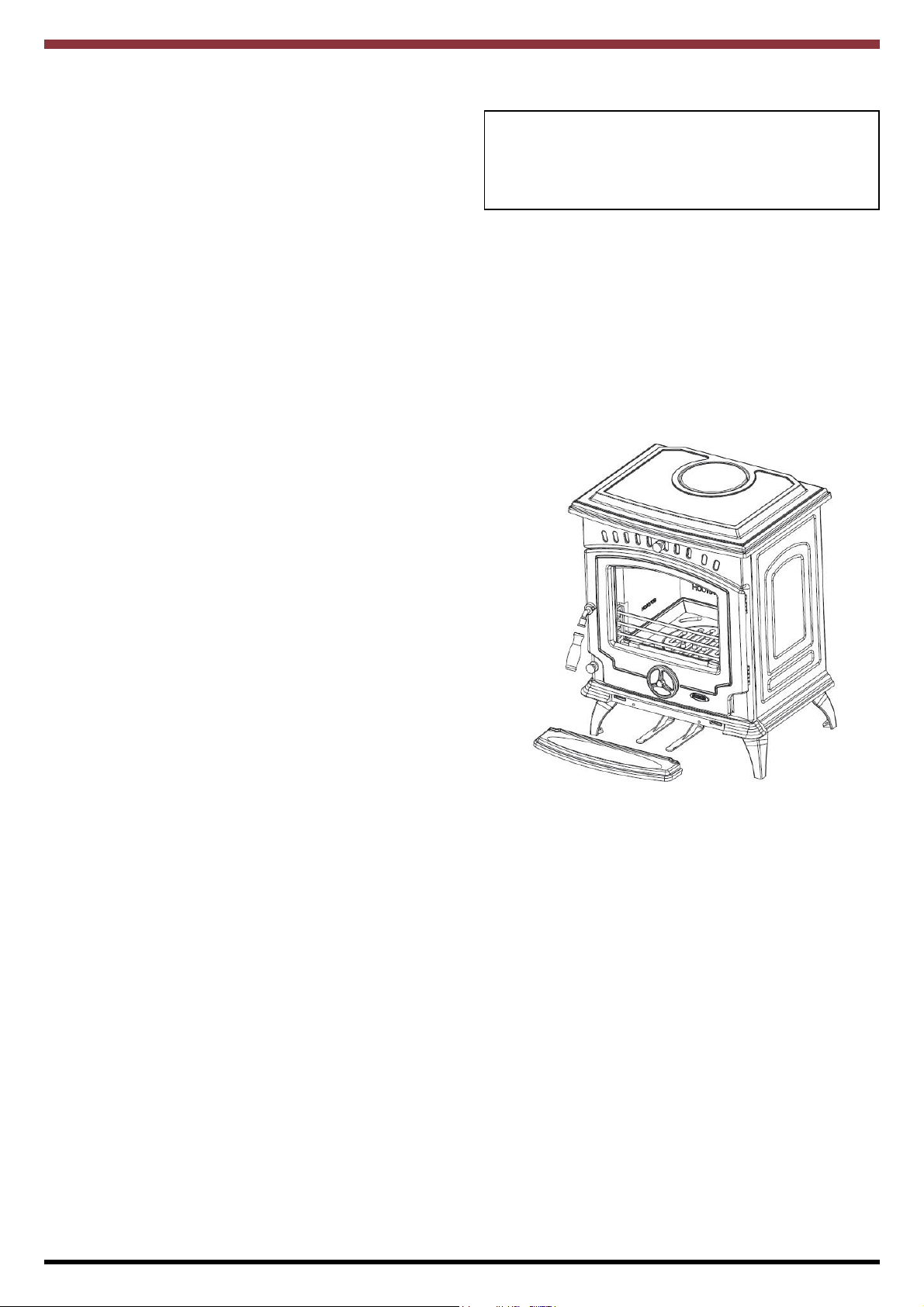
Tara Non Boiler Eco
Solid Fuel Stove
WARNING: This appliance is hot while in operation and retains its heat for a long period of time after
use. children, aged or infirm persons should be supervised at all times and should not be allowed to
touch the hot working surfaces while in use or until the appliance has thoroughly cooled.
When using the boiler stove in situations where children, aged and/or infirm persons are present a fireguard must be used to prevent accidental contact with the stove. The fireguard should be
manufactured in accordance with
BS 8423:2002.
INSTALLATION AND OPERATING INSTRUCTIONS
Page 2

TABLE OF CONTENTS
PAGE NO.
1. Warranty . . . . . . . . . . . . . . . . . . . . . . . . . . . . . . . . . . . . . . . . . . . . . . . . . . . . . . . . . . . . . . . . . . . . . . 4
2. Installation check list . . . . . . . . . . . . . . . . . . . . . . . . . . . . . . . . . . . . . . . . . . . . . . . . . . . . . . . . . . . . 5
3. General . . . . . . . . . . . . . . . . . . . . . . . . . . . . . . . . . . . . . . . . . . . . . . . . . . . . . . . . . . . . . . . . . . . . . . . 6
Handling . . . . . . . . . . . . . . . . . . . . . . . . . . . . . . . . . . . . . . . . . . . . . . . . . . . . . . . . . . . . . . . . . . . . 6
Fire Cement . . . . . . . . . . . . . . . . . . . . . . . . . . . . . . . . . . . . . . . . . . . . . . . . . . . . . . . . . . . . . . . . . 6
Asbestos . . . . . . . . . . . . . . . . . . . . . . . . . . . . . . . . . . . . . . . . . . . . . . . . . . . . . . . . . . . . . . . . . . . 6
Metal Parts . . . . . . . . . . . . . . . . . . . . . . . . . . . . . . . . . . . . . . . . . . . . . . . . . . . . . . . . . . . . . . . . . . 6
4. Pre-Installation Assembly . . . . . . . . . . . . . . . . . . . . . . . . . . . . . . . . . . . . . . . . . . . . . . . . . . . . . . . . . 6
5. Chimney . . . . . . . . . . . . . . . . . . . . . . . . . . . . . . . . . . . . . . . . . . . . . . . . . . . . . . . . . . . . . . . . . . . . . . 6
6. Flues . . . . . . . . . . . . . . . . . . . . . . . . . . . . . . . . . . . . . . . . . . . . . . . . . . . . . . . . . . . . . . . . . . . . . . . . . 7
7. Flue Pipes . . . . . . . . . . . . . . . . . . . . . . . . . . . . . . . . . . . . . . . . . . . . . . . . . . . . . . . . . . . . . . . . . . . . 7
8. Top Flue Exit . . . . . . . . . . . . . . . . . . . . . . . . . . . . . . . . . . . . . . . . . . . . . . . . . . . . . . . . . . . . . . . . . . 8
9. Rear Flue Exit . . . . . . . . . . . . . . . . . . . . . . . . . . . . . . . . . . . . . . . . . . . . . . . . . . . . . . . . . . . . . . . . . 8
10. Ventilation & Combustion Air Requirements . . . . . . . . . . . . . . . . . . . . . . . . . . . . . . . . . . . . . . . . . . 8
11. Permanent Air Vent . . . . . . . . . . . . . . . . . . . . . . . . . . . . . . . . . . . . . . . . . . . . . . . . . . . . . . . . . . . . . 9
Extractor Fan . . . . . . . . . . . . . . . . . . . . . . . . . . . . . . . . . . . . . . . . . . . . . . . . . . . . . . . . . . . . . . . . 9
12. Location . . . . . . . . . . . . . . . . . . . . . . . . . . . . . . . . . . . . . . . . . . . . . . . . . . . . . . . . . . . . . . . . . . . . . . 9
13. Installation Clearances . . . . . . . . . . . . . . . . . . . . . . . . . . . . . . . . . . . . . . . . . . . . . . . . . . . . . . . . . . . 9
14. Floor Protection . . . . . . . . . . . . . . . . . . . . . . . . . . . . . . . . . . . . . . . . . . . . . . . . . . . . . . . . . . . . . . . . 9
15. Specification Non boiler model . . . . . . . . . . . . . . . . . . . . . . . . . . . . . . . . . . . . . . . . . . . . . . . . . . . . . 10
16. Technical Data . . . . . . . . . . . . . . . . . . . . . . . . . . . . . . . . . . . . . . . . . . . . . . . . . . . . . . . . . . . . . . . . . 10
17. Handover . . . . . . . . . . . . . . . . . . . . . . . . . . . . . . . . . . . . . . . . . . . . . . . . . . . . . . . . . . . . . . . . . . . . . 11
18. Operating Instructions . . . . . . . . . . . . . . . . . . . . . . . . . . . . . . . . . . . . . . . . . . . . . . . . . . . . . . . . . . . 11
19. Suitable Fuels . . . . . . . . . . . . . . . . . . . . . . . . . . . . . . . . . . . . . . . . . . . . . . . . . . . . . . . . . . . . . . . . . . 11
20. Lighting . . . . . . . . . . . . . . . . . . . . . . . . . . . . . . . . . . . . . . . . . . . . . . . . . . . . . . . . . . . . . . . . . . . . . . . 12
21. Important Notes . . . . . . . . . . . . . . . . . . . . . . . . . . . . . . . . . . . . . . . . . . . . . . . . . . . . . . . . . . . . . . . . 13
22. Air Control Settings . . . . . . . . . . . . . . . . . . . . . . . . . . . . . . . . . . . . . . . . . . . . . . . . . . . . . . . . . . . . . 14
23. Air Controls . . . . . . . . . . . . . . . . . . . . . . . . . . . . . . . . . . . . . . . . . . . . . . . . . . . . . . . . . . . . . . . . . . . 14
24. Recommended Fuels . . . . . . . . . . . . . . . . . . . . . . . . . . . . . . . . . . . . . . . . . . . . . . . . . . . . . . . . . . . . 14
25. Overnight Burning . . . . . . . . . . . . . . . . . . . . . . . . . . . . . . . . . . . . . . . . . . . . . . . . . . . . . . . . . . . . . . 15
26. Re-fuelling . . . . . . . . . . . . . . . . . . . . . . . . . . . . . . . . . . . . . . . . . . . . . . . . . . . . . . . . . . . . . . . . . . . . 15
27. De-Ashing . . . . . . . . . . . . . . . . . . . . . . . . . . . . . . . . . . . . . . . . . . . . . . . . . . . . . . . . . . . . . . . . . . . . . 16
28. Disposal of Ashes . . . . . . . . . . . . . . . . . . . . . . . . . . . . . . . . . . . . . . . . . . . . . . . . . . . . . . . . . . . . . . . 15
28. Chimney Cleaning . . . . . . . . . . . . . . . . . . . . . . . . . . . . . . . . . . . . . . . . . . . . . . . . . . . . . . . . . . . . . . 16
29. To Clean Chimney Outlet (Boiler / Non Boiler Model ) . . . . . . . . . . . . . . . . . . . . . . . . . . . . . . . . . . 16
30. To Replace Fire Grate . . . . . . . . . . . . . . . . . . . . . . . . . . . . . . . . . . . . . . . . . . . . . . . . . . . . . . . . . . . 16
31. CO Alarm . . . . . . . . . . . . . . . . . . . . . . . . . . . . . . . . . . . . . . . . . . . . . . . . . . . . . . . . . . . . . . . . . . . . . 16
32. Fire Safety . . . . . . . . . . . . . . . . . . . . . . . . . . . . . . . . . . . . . . . . . . . . . . . . . . . . . . . . . . . . . . . . . . . . 17
2
Page 3
TABLE OF CONTENTS
PAGE NO.
33. Vitreous Enamel Cleaning . . . . . . . . . . . . . . . . . . . . . . . . . . . . . . . . . . . . . . . . . . . . . . . . . . . . . . . . 17
34. Glass Cleaning . . . . . . . . . . . . . . . . . . . . . . . . . . . . . . . . . . . . . . . . . . . . . . . . . . . . . . . . . . . . . . . . . 17
35. Glass Replacement . . . . . . . . . . . . . . . . . . . . . . . . . . . . . . . . . . . . . . . . . . . . . . . . . . . . . . . . . . . . . 17
36. Exploded view . . . . . . . . . . . . . . . . . . . . . . . . . . . . . . . . . . . . . . . . . . . . . . . . . . . . . . . . . . . . . . . . . 18
37. Trouble Shooting . . . . . . . . . . . . . . . . . . . . . . . . . . . . . . . . . . . . . . . . . . . . . . . . . . . . . . . . . . . . . . . 19
3
Page 4
STANLEY SOLID FUEL STOVE WARRANTY
CONDITIONS OF WARRANTY
Your Stanley Solid Fuel Stove is guaranteed against any part that fails (under normal operating conditions) as detailed
in the following table with timelines specified from the date of installation of the appliance. If the unit is not installed with-
in six months of date of purchase, the warranty will commence six months from the date of purchase.
Warranty Period Parts Covered (Parts & Labour unless Stated)
Up to 1 Year • Refractory materials (supply only)
• Rope seals, glass seals and cement seals.
• Surface Finish on Seno models.
• Grates and fire bars.
• Ceramic glass is covered for Thermal breakage (supply only).
• Rust (if reported before installation)
• Aesthetic Damage (provided reported on date of receipt)
Up to 5 Years • All external castings & enamel finishes (excluding impact damage or
damage caused by overfiring). Pictures of damage must be submitted to
WS Service Department.
Up to 3 Years • Boiler - A Leaking Boiler Report must be conducted by an Authorised
Stanley Service Engineer and submitted to WS Service Department for re
view.
All warranty claims must be reported to the Waterford Stanley Service Department and must be submitted with the product serial number (located on the front casting), date of purchase, proof of purchase (if requested) and details of the
specific nature of the problem.
The warranty is given only to the original consumer/purchaser only and is non- transferable. The appliance must be
installed by a suitable qualified person and installed as per the requirements of the manual. Failure to comply with the
Installation requirements or Building Regulations will void your warranty. Waterford Stanley reserve the right to replace
any part due to manufacturing defect that fails within the warranty period under the terms of the warranty. The unit must
be used for normal domestic purposes only and in accordance with manufacturer's operation instructions.
LIMITS OF LIABILITY
The warranty does not cover:
* Special, incidental or consequential damages, injury to persons or Property, or any other consequential loss.
* Any issue caused by negligence, misuse, abuse or circumstances beyond Waterford Stanley’s control.
* Any issue with wear and tear, modification, alteration, or servicing by anyone other than an authorized service
engineer.
* Installation and operational related problems such as draught related issues external to the stove, inadequate
venting or ventilation, excessive flue offsets, negative air pressure caused by insufficient burning of improper
fuel.
* Damage caused to the unit while in transit.
* Enamel discolouration due to over firing, enamel damage caused by impact, damage to baffles caused by
over firing and fading of surface finish on casting.
* Stress fractures on bricks.
* Rust on cast iron parts unless reported prior to unit being installed.
* Aesthetic damage, rust & missing parts on units purchased off display.
Note: Adequate clearance must be maintained around the appliance to ensure the ease of part removal in the possible event of their damage/failure. Waterford Stanley are not responsible for any costs incurred in the removal of items
installed in the vicinity of the appliance that have to be moved to facilitate a part replacement.
4
Page 5
INSTALLATION CHECK LIST
Flue System
1. Minimum Flue Height of 4.5 metres (15 feet).
2. Appliance should be connected to a minimum of 1.8 metres (6 feet) of 150mm (6”)
flue pipe with a horizontal run not exceeding 150mm (6”).
3. Appliance should be connected to a chimney of less than 200mm (8”) in diameter
(otherwise the chimney must be lined with a 6” flue liner).
4. The chimney venting position must be above the main ridge of the roof or adjacent
outside obstructions.
5. The chimney serving this appliance should not serve any other appliance.
6. Access should be provided to the chimney serving the appliance to allow for cleaning.
Location
7. Clearance to combustible materials must be adhered to as described in the Clearance
to Combustible section.
Tick
8. The stove must be installed on a floor protector that covers the area under the stove
and extends 18” to the front & 8” to the sides and back.
Plumbing
9. Appliance must be connected to a gravity circuit using 1” ID flow & return piping.
10. The length of pipes from the cylinder to the cooker should not exceed 7.8 metres
1
(25
/2 feet).
11. A circulation pump should be fitted to the return pipe of the radiator circuit and controlled by
a pipe stat fitted to the flow pipe of the gravity circuit to the cylinder.
(Not applicable to DHW Model).
Ventilation & Combustion Air Requirements
12. The room in which the appliance is located should have an air vent of adequate
size to support correct combustion (see Ventilation & Combustion Air Requirement
Section for specific details).
5
Page 6
TARA SOLID FUEL CENTRAL HEATING STOVE
INSTALLATION & OPERATING INSTRUCTIONS
GENERAL
When installing, operating and maintaining your
Tara Stove respect basic standards of fire safety.
Read these instructions carefully before commencing the installation. Failure to do so may result in
damage to persons and property. Consult your local
Municipal office and your insurance representative
to determine what regulations are in force. Save
these instructions for future reference.
Please note that it is a legal requirement under
England & Wales Building Regulations that the
installation of the stove is either carried out under
Local Authority Building Control approval or is
installed by a Competent Person registered with a
Government approved Competent Persons
Scheme. HETAS Ltd operate such a scheme and a
listing of their Registered Competent Persons can
be found on their website at www.hetas.co.uk.
Special care must be taken when installing the stove
such that the requirements of the Health & Safety at
Work Act are met.
The complete installation must be done in accordance with current Standards and Local Codes. It
should be noted that the requirements and these
publications may be superseded during the life of
this manual.
PRE INSTALLATION ASSEMBLY
1. After removing the stove from its pack, open
the front door and remove the contents.
2. Fit the front door handle using the M8 screw,
as shown in Fig.1.
3. Remove the stove from the wooden pallet.
4. Fit the front ash tray by slotting into place on
the front and secure it using the screws
provided.
Fig.1
Handling
Adequate facilities must be available for loading,
unloading and site handling.
Fire Cement
Some types of fire cement are caustic and should
not be allowed to come into contact with the skin. In
case of contact with the skin wash immediately with
plenty of water.
Asbestos
This stove contains no asbestos. If there is a possibility of disturbing any asbestos in the course of
installation then please seek specialist guidance and
use appropriate protective equipment.
Metal Parts
When installing or servicing this stove care should
be taken to avoid the possibility of personal injury.
“IMPORTANT WARNING”
This stove must not be installed into a chimney that
serves any other heating appliance.
There must not be an extractor fan fitted in the same
room as the stove as this can cause the stove to
emit fumes into the room.
CHIMNEY
Do not connect to a chimney serving another
appliance.
The stove is a radiant room heater and must be connected to a chimney of the proper size and type.
The chimney must have a cross-sectional area of at
least 30 square inches 18150sq. mm or a diameter
of at least 6” (150mm). It is best to connect to a
chimney of the same size, as connection to a larger
size may result in a somewhat less draught. Do not
connect to a chimney serving another appliance.
6
Page 7

Minimum chimney height 15’(4.1 meters) from floor
on which stove is installed. An existing masonry
chimney should be inspected and if necessary
repaired by a competent mason. The stove must be
connected to a chimney with a minimum continuous
draft of .06 wg. Poor draft conditions will result in
poor performance.
In adverse weather conditions, down drafts may be
experienced causing smoke or fumes to spill into the
room. If this occurs shut the appliance down by
closing the air controls. If the problem persists seek
the advice of a chimney sweep.
Fig 2
suffice it may be necessary to extend the flue pipe
so that the termination point is above the apex. (See
Fig.3)
Fig 3
2300
1000
FLUES
Flues should be vertical wherever possible and
where a bend is necessary, it should not make an
angle of more than 45owith the vertical. Horizontal
flue runs should be avoided except in the case of a
back outlet appliance, when the length of the horizontal section should not exceed 150mm.
In order to minimise flue resistance and to make
sweeping easier it is recommended to use 2 x 45
bends rather than a 90obend.
Appliance
Soot Door
FLUE PIPES
A flue pipe should only be used to connect an appliance to a chimney and should not pass through any
roof space.
Flue pipes may be of any of the following materials:
(a) Cast iron as described in BS 41: 1973
(1981), or
(b) Stainless steel with a wall thickness of
at least 1mm and as described in BS
EN 10095:1999 Specification for
stainless and heat resisting steel
plate, sheet and strip, for Grade 316
S11, 316 S13, 316 S16, 316 S31,
316 S33, or the equivalent Euronorm
o
88-71 designation, or
(c) Vitreous enamelled steel complying with BS
6999: 1989.
The flue termination point must be located to minimise any wind effects. Wind effects of suction,
pressure zones and turbulence can be created by
the roof and adjacent objects. Wind effects can also
be created by natural land contours.
To minimise the wind effects, the flue termination
point should be located a minimum of 1000mm from
the roof measured vertically and 2300mm measured
horizontally. Where this termination point does not
Flue pipes with spigot and socket joints should be fitted with the socket uppermost.
Clearance to combustibles must be adhered to
when fitting the flue pipe.
The appliance is suitable for continuous operation
on solid mineral fuel and intermittent operation on
wood logs.
7
Page 8

TOP FLUE EXIT
For top outlet configuration remove the hob from the
top of the stove, turn the hob upside down and place
it on the floor, taking care not to damage it. Remove
the hob blanking plate by unscrewing the two
screws from underneath the hob.
Next remove the flue blanking plate from the top of
the stove by unscrewing the two screws, connect
this blanking plate to the rear flue outlet at the back
of the stove. Replace the hob in the correct position.
Connect the connector pipe (not supplied) into the
top flue outlet socket at the top of the stove and
cement into place using approved fire cement ensuring that no cement blocks the flue passageway.
Fig 4
Fig. 5
VENTILATION & COMBUSTION AIR REQUIREMENTS
It is imperative that there is sufficient air supply to
the stove in order to support correct combustion.
The air supply to this appliance must comply with
B.S. 8303: Part 1.
REAR FLUE EXIT
For rear flue outlet configuration push in flue connector pipe (not supplied) into flue outlet socket at
the rear of the stove and cement into place using
approved fire cement ensuring that no cement
blocks the flue passageway.
It is recommended that a minimum clearance of
100mm be maintained from the sides and rear of the
appliance to a tiled fireplace or masonry wall, especially on the right of the appliance as access is
required for the controls.
The minimum effective air requirement for this appliance is 21cm2(3.25in2). When calculating combustion air requirement for this appliance use the following equation: a total free area of at least 550mm
per kW of rated output above 5kW shall be provided.
If there is another air using appliance fitted in the
same or adjacent room, it will be necessary to calculate additional air supply.
All materials used in the manufacture of air vents
should be such that the vent is dimensionally stable
and corrosion resistant.
The effective free area of any vent should be ascertained before installation. The effect of any screen
should be allowed for when determining the effective
free area of any vent.
Air vents direct to the outside of the building should
be located so that any air current produced will not
pass through normally occupied areas of the room.
An air vent outside the building should not be located less than the dimensions specified within the
Building Regulations from any part of any flue terminal. These air vents must also be fire proofed as per
Building Regulations.
Air vents in internal walls should not communicate
with bedsits, toilets, bathrooms or rooms containing
a shower.
2
Air vents traversing cavity walls should include a
continuous duct across the cavity. The duct should
be installed in such a manner as not to impair the
weather resistance of the cavity.
8
Page 9

Joints between air vents and outside walls should be
sealed to prevent the ingress of moisture. Existing
air vents should be of the correct size and unobstructed for the appliance in use.
It is recommended that this appliance is sited next to
and on a non-combustible surface. A minimum all
round clearance of 100 mm will allow air circulation
and not impede the performance of the stove.
Where such a installation exists, a test for spillage
should be made with the fan or fans and other appliances using air in operation at full rate, (i.e. extraction fans, tumble dryers) with all external doors and
windows closed.
If spillage occurs following the above operation, an
additional air vent of sufficient size to prevent this
occurrence should be installed.
PERMANENT AIR VENT
The stove requires a permanent and adequate air
supply in order for it to operate safely and efficiently.
In accordance with current Building Regulations the
installer will have fitted a permanent air supply vent
into the room in which the stove is installed to provide combustion air. This air vent should not under
any circumstances be shut off or sealed.
Extractor Fan
There must not be an extractor fan fitted in the same
room as the stove as this can cause the stove to
emit smoke and fumes into the room.
The connector may pass through walls or partitions
constructed of combustible materials provided the
connector is either listed for wall pass-through or is
routed through a device listed for a wall passthrough and is installed in accordance with the conditions of the listing. Any unexposed metal that is
used as part of a wall pass-through system is
exposed to flue gases shall be constructed of stainless steel or other equivalent material that will resist
corrosion, softening, or cracking from flue gas at
temperatures up to 982oC.
FLOOR PROTECTION
It is recommended that this appliance is installed on
a solid, level, non- combustible hearth conforming to
current Building Regulations.
The hearth should extend at least 127mm from the
sides and rear of the stove and 460mm from the
front. See Fig. 6.
LOCATION
There are several conditions to be considered in
selecting a location for your Tara Stove.
a. Position in the area to be heated, central
locations are usually best.
b. Allowances for proper clearances to
combustibles.
INSTALLATION CLEARANCES
Clearance to combustible materials (Non Boiler
Model)
From the front - 900mm
From the sides - 460mm
From the back - 700mm
From the flue pipe - 600mm
Fig.6
9
Page 10

NON BOILER STOVE
SPECIFICATION
Note: Dimensions stated are in millimetres and may be subject to a slight +/- variation.
TECHNICAL DATA
MODEL NON BOILER
Parameter Wood Mineral smokeless fuel
Max Heat Output (kW) 8 8
Nominal Heat Output (kW) 6.7 7.1
Output to Room (kW) 6.7 7.1
Typical Refuel Interval To Achieve Nominal Outputs(h) 0.8 1
Mean Flue Gas Temp. (oC) 314 304
Efficiency % 80.5 78.3
Flue gas mass flow ( g/s)
Gross Weight (kg) 135
Flue Outlet Diameter (mm) 150
Wood Log Size (mm) 300 N/A
4.5 5.6
Mean CO emission (at 13 % O2) % 0.10 0.11
Mean CnHm (at 13 % O2) Nmg/m
Mean NOx (at 13 % O2) Nmg/m
DIN Plus dust (at 13 % O2) Nmg/m
Energy
Model
Tara NB A+ 7.4 N/A 107.73 Wood 7.4 81.0
Efficiency Class
Heat Output to
Room
Heat Output to
Water
3 43 58
3 82 97
3 17 32
Energy
Efficiency Index Preferred Fuel
Nominal Heat
Output Net Efficiency
10
Page 11

HANDOVER
On completion of the installation allow a suitable
period of time for any fire cement and mortar to dry
out, when a small fire may be lit and checked to
ensure the smoke and fumes are taken from the
stove up the chimney and emitted safely to the
atmosphere. Do not run at full output for at least 24
hours.
Ensure that the operating instructions for the stove
are left with the customer. Ensure to advise the customer on the correct use of the appliance with the
fuels likely to be used on the stove and warn them to
use only the recommended fuels for the stove.
Advise the user what to do should smoke or fumes
be emitted from the stove. The customer should be
warned to use a fireguard to BS 6539 in the presence of children, aged and/or infirm persons.
OPERATING INSTRUCTIONS
Fig.8
WARNINGS :-
If there is a possibility that a part of the heating
system may be frozen you should not light the
stove until you are confident that the system is
free of ice, has no leaks and water is able to fully
circulate.
Parts become very hot while the stove is in use
and should not be touched with bare hands.
Special operating tool is provided for operation
of the hot stove.
SUITABLE FUELS
COAL, ANTHRACITE, PEAT, WOOD SYNTHETIC
LOGS, OR OTHER FUELS. “Never use gasoline”
gasoline type lantern fuel, kerosene, charcoal lighter
fluid or similar liquids to start or ‘freshen up’ a fire in
this heater. Keep all such liquid well away from the
heater at all times. Operate stove only with fuelling
door closed. This heater is hot whilst in operation.
Keep children, clothing and furniture a safe distance
away.
11
Page 12

LIGHTING
Before lighting the stove check with the installer that the installation work and
commissioning checks described in the installation instructions have been
carried out correctly and that the chimney has been swept clean, is sound
and free from any obstructions. As part of the stove’s handover the installer
should have demonstrated how to operate correctly.
1. Before lighting the stove, ensure that any build up of ashes in the fire
box has been removed and that the ashpan has been emptied.
2. Open the firebox and cover the grate with crumpled pieces of paper.
3. Lay pieces of kindling on top of the paper towards the back of the fire
box.
4. Open the primary air inlet by turning the spin valve at the front of the
stove anticlockwise.
5. Open the secondary air control by sliding the control knob located
over the top of the fire door to the left.
6. Ignite the paper and close the firedoor.
7. When the kindling is well alight, open the fire door and add more kindling of a larger size to sustain the fire. Close the firedoor.
8. Never use inflammable liquid i.e. gasoline, petrol paraffin etc. to
start or “freshen up” afire in this heater.
9. When a hot bed of fuel is established, add the normal fuel and adjust
the spin valve to the required setting.
10. To shut the fire down, do not add fuel, make sure that the firedoor is
properly closed and that the primary and secondary air controls are all
in the closed position. Cutting off the air supply will reduce the heat
output.
11. Following a prolonged shutdown of the appliance perhaps after the
summer break, ensure the flueway is free from obstruction prior to
re-lighting.
Re-fuelling -Open the firedoor and reload, close the firedoor.
12
Page 13

IMPORTANT NOTES
Now that your Stanley Solid Fuel Stove is installed and no doubt you are looking forward to many comforts it
will provide, we would like to give you some tips on how to get the best results from your stove.
1. We would like if you could take some time to read the operating instructions/hints, which we are
confident, will be of great benefit to you.
2. Do not burn fuel with a high moisture content, such as a damp peat or unseasoned timber. This
will only result in a build up of tar in the stove and in the chimney.
FUEL CALORIFIC VALUES - SOLID FUELS
Anthracite 25-50mm C.V.: 8.2kW/Kg 14,000 BTUs/lb
House Coal 25-75mm C.V.: 7.2kW/Kg 12,000 BTUs/lb
Timber - Firebox size C.V.: 5.0kW/Kg 8,600 BTUs/lb
Peat Briquettes C.V.: 4.8kW/Kg 8,300 BTUs/lb
3. Clean the flue-ways of the stove every week and ensure that there are no blockages. Check
flueways before lighting especially after a shut down period. Please refer to manual for
instructions.
4. Before loading fresh fuel into the firebox, riddle fully to remove all ashes this will allow better and
cleaner burning. See Re-Fuelling Section.
5. Never allow a build up of ashes in the ash pan, as this will cause the grate to burn out prematurely. Empty the ashpan when re-fuelling.
6. Allow adequate air ventilation to ensure plenty of air for combustion.
7. Do not use as an incinerator burning rubbish/household waste.
8. Do not leave ash-door open for long periods as this will over heat the unit causing unnecessary
damage. Close the ash door between removing and replacing the ashpan.
9. Clean the chimney at least twice a year.
10. Burning soft fuels such as timber and peat will stain the glass. Regular cleaning will prevent permanent staining. Clean with soapy water when cool.
11. Keep all combustible materials a safe distance away from unit, please consult manual for clearance to combustible table.
12. For safety reasons never leave children or the elderly unaccompanied while stove is in use. Use
a fire guard.
13. Avoid contact with unit when in use as stove reaches very high operating temperatures.
14. This appliance should be regularly maintained by a competent service engineer.
15. Do not use aerosol sprays near the stove when it is lighting.
Use only replacement parts recommended by Stanley. Making unauthorised modifications, or using
unauthorised parts will invalidate your guarantee and may cause damage or injury.
AN ODOUR WILL EMIT FROM STOVE ON FIRST FIRING, WHEN FIRE REACHES MAXIMUM
TEMPERATURE OVER A NUMBER OF HOURS THE ODOUR WILL SUBSIDE.
IT IS BEST ADVISED TO OPEN WINDOWS DURING THIS PERIOD.
THE ODOUR IS UNPLEASANT BUT NOT TOXIC. YOU MAY WISH TO VACATE THE ROOM WHILE THE
PAINT CURES.
13
Page 14

AIR CONTROL SETTINGS
Fuel Ignition Controlled Burn
Primary Secondary Primary Secondary
Anthracite Fully Open Fully Closed 0-80% Open Fully Closed
Coal Fully Open Fully Open 0-80% Open 0-50% Open
Wood/ Turf Fully Open Fully Open 0-10% Open 0-80% Open
Fig.9
Secondary air
control
AIR CONTROLS
The stove has two air controls, the controls operate
by pushing in to close and pull out to open, the secondary air control on the left hand side controls air
entering the stove via the air wash over the glass
and the air holes at the rear of the firebox. The primary air control on the right hand side controls the
air entering the stove under the grate. When lighting
the stove bothe air controls can be pulled out fully to
allow the maximum air supply to the stove, when the
fire becomes established the air controls should be
adjusted depending on the fuel used to give a controlled burn. For setting of air controls during when
the fire is established view the above table of air
control settings.
Primary air
control.
This appliance has been tested using seasoned
wood logs and manufactured briquetted smokeless
fuel (Ancit) for closed appliances, sized between
20g and 140g. Other fuels are commercially available and may give similar results. Wood logs up to
406mm long are suitable. All fuels should be stored
under cover and kept as dry as possible prior to use.
Do not use fuels with a Petro-coke ingredient as this
may cause the grate to overheat, causing damage.
Reduced outputs will result when fuels of lower
calorific values are used. Never use gasoline or
gasoline type lantern fuel, kerosene, charcoal lighter
fluid or similar liquids to start or freshen up a fire in
this heater. Keep all such liquid well away from the
heater at all times. Operate the stove only with the
fuelling door closed except for re-fuelling.
This stove has obtained HETAS Ltd approval for
burning natural and manufactured smokeless fuels
and wood logs only as detailed in recommended
fuels below. HETAS Approval does not cover the
use of other fuels either alone or mixed with the recommended fuels listed, nor does it cover instructions
for the use of other fuels.
RECOMMENDED FUELS
All fuels should be stored under cover and kept
as dry as possible prior to use.
14
Page 15

WARNING:
DE-ASHING
Properly installed, operated and maintained this
stove will not emit fumes into the dwelling.
Occasional fumes from de-ashing and re-fuelling
may occur. However, persistent fume emission is
potentially dangerous and must not be tolerated. If
fume emission does persist, then the following
immediate action should be taken -
(a) Open doors and windows to ventilate room.
(b) Let the fire out or eject and safely dispose of
fuel from the stove.
(c) Check for flue or chimney blockage and clean
if required.
(d) Do not attempt to relight the fire until the cause
of the fume emission has been identified and
corrected. If necessary seek expert advice.
The most common cause of fume emission is flueway or chimney blockage. For your own safety
these must be kept clean at all times.
OVERNIGHT BURNING
To achieve an overnight or a low burn rate, close the
Secondary air control fully, close the primary air control or leave it marginally open depending on
draught conditions. If the fuel load is too small or the
draught too strong primary air control may need to
be closed further to sustain the low burn rate.
REMEMBER: Coal gases are toxic.
WARNING: Failure to comply with the Installation
and Operating Instructions outlined above may
result in carbon monoxide entering the house rather
than being drawn up the chimney.
Never allow ashpan to over fill as it will cause damage to fire fence. When ash build-up becomes
excessive in the fire chamber riddle the fire until all
dead ash has fallen through to the ashpan. Open the
front door and remove ashpan using the operating
tool Close the front door When the ash is disposed
of, replace the empty ashpan.
Fig.10
DISPOSAL OF ASHES
The ashpan must be emptied every day.
If ashes are allowed to build up to grate level the firebox insert could be damaged by overheating. We
recommend that you remove ashes after you have
riddled the fire.
Ashes should be placed in a metal or other noncombustible container with a tight fitting lid. The
closed container of ashes should be placed on a
non-combustible material, pending final disposal. If
ashes are buried in soil, or otherwise dumped they
should be retained in the closed container until they
are thoroughly cooled.
RE-FUELLING
Riddle the fire by connecting the grate operating tool
onto the rocker connection located at the bottom
front of the stove, then gently pull and push the rocker arm until all dead ash has fallen through into the
ashpan. Before opening the door, open the primary
air control by pulling out the control, as this will help
to eliminate any smoke or fly ash resident in the
combustion chamber. Add fuel to the fire, close fire
door and re-set the air control to required setting.
Fig.11
15
Page 16

CHIMNEY CLEANING
TO REPLACE FIRE GRATE
The chimney and any connecting flue-pipe must be
swept least once a year for smokeless fuels and a
minimum of twice a year for bituminous coal.
Always clean the appliance flue-ways, flue-pipe and
chimney prior to lighting up after a prolonged shutdown period.
Where it is not possible to sweep the chimney
through the appliance provide access in the form of
a cleaning door on the flue pipe.
Where the chimney is believed to have served an
open fire installation it is recommended that the
chimney be swept a second time within a month of
regular use after installation. It is important to clean
the appliance flue-ways, flue-pipe and chimney prior
to lighting up after a prolonged shut-down period.
The chimney must be swept and examined for
soundness and suitability before the appliance is
installed. Remedial action should be taken if
required, seeking expert advice if necessary.
Where the chimney is believed to have previously
served an open fire installation it is possible that the
higher flue gas temperature from a closed appliance
may loosen deposits that were previously firmly
adhered, with the consequent risk of flue blockage.
It is therefore recommended that the chimney be
swept a second time within a month of regular use
after installation.
TO CLEAN CHIMNEY OUTLET
Remove the fire bricks on each side. Remove the
baffle by first lifting it up and pulling it forward, then
rotate it down around the baffle supports. Replace
the baffle, the firebricks before the fire is lit. Ensure
the baffle is located correctly resting on top of the
secondary air supply steelwork and resting in front
of the tabs protruding from the top of the secondary
air steelwork.
Remove the 3 fire fence at the front of the stove,
unscrew the pull rod knob from the pull rod bar located at the front of the stove in the bottom left hand
corner. Pull the circular firegrate in the centre of the
stove upwards to the right as far as is possible.
Then twist the circular firegrate so that the front
edge is lifted up and the back edge is moved down
through the hole in the firebed insert. Push the circular firegrate down through the firebed insert.
The circular firegrate can then be removed by pushing it to the rear of the stove to relieve the pull rod
bar and then putting it out under the firebox insert.
The firebox insert can be removed by fitting the firebox insert up at the front, then rotate the firebox
insert until it can slide diagonally forward through the
opening in the front panel.
Replace any damaged parts and replace firebox
insert and grate ensuing that the pull rod is inserted
back through the opening on the left hand side of the
boiler and also through the hole on the front panel.
Replace the pull rod knob and the 3 fire fence before
relighting.
CO ALARM
The fitting of CO Alarms in the same room as the
appliance is a compulsory requirement under current Building Regulations. For ROI an additional CO
Alarm must be fitted either inside each bedroom or
within 5 metres of the bedroom door, refer to
Building Regulations Part J. Further guidance on the
installation of a carbon monoxide alarm is available
in BS EN 50292:2002 and from the alarm manufacturers instructions.
Provision of an alarm must not be considered a
substitute for either installing the appliance
correctly or ensuring regular servicing and
maintenance of the appliance and chimney
system.
WARNING:-
If the CO Alarm sounds unexpectedly:-
1. Open Doors and windows to ventilate the
room and then leave the premises.
2. Let the fire go out.
16
Page 17

FIRE SAFETY
GLASS CLEANING
To provide reasonable fire safety, the following
should be given serious consideration.
1. Do not over fire the stove.
2. Overfiring will also damage painted or enamel
finish.
3. Install a smoke detector in the room.
4. A conveniently located class “A” fire extinguisher to contend with small fires resulting
from burning embers.
5. A practical evacuation plan.
6. A plan to deal with a chimney fire as follows:-
(a) Notify the fire department.
(b) Prepare occupants for immediate
evacuation.
(c) Close all openings into the stove.
(d) While awaiting the fire department watch
for ignition to adjacent combustibles from
overheated stove pipe or from embers or
sparks from the chimney.
The glass will self clean when there is sufficient heat
generated by the burning fuel. If a build-up of creosote occurs on the glass it may be due to draft conditions, poor quality fuel or very low burning for a
long time. It is best to clean the glass when it is
thoroughly cooled.
Fig.12
GLASS REPLACEMENT
VITREOUS ENAMEL CLEANING
General cleaning must be carried out when the
stove is thoroughly cool.
If this stove is finished in a high gloss vitreous
enamel, to keep the enamel in the best condition
observe the following tips:
1. Wipe over daily with a soapy damp cloth,
followed by a polish with a clean dry duster.
2. For stubborn deposits a soap impregnated
pad can be carefully used on the vitreous
enamel.
3. Only products recommended by the Vitreous
Enamel Association, these products carry
the Vitramel label.
(a) Open the front door fully.
(b) Remove the four corner screws and clips
and carefully remove the broken glass.
(c) Clean the glass recess in the door.
(d) Attach adhesive thermal tape to the
perimeter of the replacement glass.
(e) Place the thermal tape side of the glass into
the door recess and replace the four corner
clips.
(f) Tighten screws.
(g) Replace glass only with ceramic glass 5mm
thick.
4. DO NOT USE ABRASIVE PADS OR OVEN
CLEANSERS CONTAINING CITRIC ACID
ON ENAMELLED SURFACES. ENSURE
THAT THE CLEANSER MANUFACTURERS INSTRUCTIONS ARE ADHERED TO.
17
Page 18

TARA NB EXPLODED VIEW
18
Page 19

TROUBLE SHOOTING
PROBLEM POSSIBLE CAUSE ACTION
Fire difficult to start Unseasoned wood, too damp or
poor quality.
Logs too big
Fire Goes Out Air Starvation
Insufficient Draught
Fire Burns Too Quickly Too much draught
Poor Quality Wood/Fuel
Smokes When Lighting Up Flue duct is cold Burn paper and kindling to
Use recommended fuel only.
To light fire use small, very dry
twigs. To maintain fire use split
logs.
Open lower spin wheel and top air
control lever.
Check that the flue is not obstructed, sweep if necessary - (seek
advice from a chimney specialist).
Ensure that the lower spin wheel is
closed and partially close the top
air control lever.
Do not continuously burn small
wood, sticks, bundles , carpentry
off-cuts (plywood / pallets etc)
increase heat.
Smokes While Burning Draught is insufficient
Down Draught
Room is in decompression
Low Heat Output Incorrect Fuels Use the recommended Fuel
Fire Shuts Down After a Period
of Time
Excessive Condensation On The
Boiler
Insufficient Water Circulation
Through The Boiler
Cold Water Being Circulated
Fuel used Has Excessive
Moisture Content
Consult a chimney specialist.
Check that the flue is not obstructed, sweep if necessary.
Install an anti-down draught cowl.
Consult your dealer.
In houses equipped with
Mechanical Ventilation, an outside
air intake must be installed for the
chimney.
Check Plumbing
Check That Pipe Thermostat Is
Fitted And Set Correctly
Season Fuel to Achieve Lower
Moisture Content
19
Page 20

Manufactured by
Waterford Stanley Ltd.,
Unit 401-403, IDA Industrial Estate, Cork Road,
Waterford, Ireland.
Tel: (051) 302300 Fax (051) 302315
20
N00841AXX
REV:001 NH 030519
 Loading...