

Page 1
STSC2135
English Page 3
Turkish Page 12
Page 2

2
DIAMETER OF WORK PIECE
WIDTH OF SPACE BLOCK
SPACE BLOCK
E
F
X
.3"
(8mm)
FIG. A
FIG. B
FIG. E
FIG. I
FIG. D
E
H
I
F
P
FORWARD
FIG. G
L
FIG. H
R
J
U
T
S
Y
W
V
K
J
F
H
I
L
N
o
A
M
G
X
E
D
FIG. C
CUT-OFF END
BLOCK
C
B
F
P
A
E
FIG. F
P
E
AD
ENGLISH (Original instructions)
Page 3

3
Intended use
Your STANLEY Chop Saw has been designed for the cutting
of variously shaped steel materials.
General safety rules
Warning! Read all instructions. Failure to follow all
instructions listed below may result in electric shock, fire
and/or serious injury. The term “power tool” in all of the
warnings listed below refers to your mains operated
(corded) power tool or battery operated (cordless) power
tool. SAVE THESE INSTRUCTIONS.
Safety instructions
General power tool safety warnings
1. Work area safety
a. Keep work area clean and well lit. Cluttered and dark
areas invite accidents.
b. Do not operate power tools in explosive
atmospheres, such as in the presence of flammable
liquids, gases or dust. Power tools create sparks
which may ignite the dust or fumes.
c. Keep children and bystanders away while operating
a power tool. Distractions can cause you to lose
control.
2. Electrical safety
a. Power tool plugs must match the outlet. Never
modify the plug in any way. Do not use any adapter
plugs with earthed (grounded) power tools.
Unmodified plugs and matching outlets will reduce risk
of electric shock.
b. Avoid body contact with earthed or grounded
surfaces such as pipes, radiators, ranges and
refrigerators. There is an increased risk of electric
shock if your body is earthed or grounded.
c. Do not expose power tools to rain or wet conditions.
Water entering a power tool will increase the risk of
electric shock.
d. Do not abuse the cord. Never use the cord for
carrying, pulling or unplugging the power tool. Keep
cord away from heat, oil, sharp edges or moving
parts. Damaged or entangled cords increase the risk of
electric shock.
e. When operating a power tool outdoors, use an
extension cord suitable for outdoor use. Use of a
cord suitable for outdoor use reduces the risk of electric
shock.
f. If operating a power tool in a damp location is
aunavoidable, use a residual current device
(RCD)protected supply.Use of an RCD reduces the
risk of electric shock.
Note: The term "Residual Curent Device (RCD)" can be
replaced by "Ground Fault Circuit Interrupter (GFCI)" or by
"Earth Leakage Circuit Breaker (ELCB)".
3. Personal safety
a. Stay alert, watch what you are doing and use
common sense when operating a power tool. Do not
use a power tool while you are tired or under the
influence of drugs, alcohol or medication. A moment
of inattention while operating power tools may result in
serious personal injury.
b. Use safety equipment. Always wear eye protection.
Safety equipment such as dust mask, non-skid safety
shoes, hard hat, or hearing protection used for
appropriate conditions will reduce personal injuries.
c. Avoid accidental starting. Ensure the switch is in the
off position before plugging in. Carrying power tools
with your finger on the switch or plugging in power tools
that have the switch on invites accidents.
d. Remove any adjusting key or wrench before turning
the power tool on. A wrench or a key left attached to a
rotating part of the power tool may result in personal
injury.
e. Do not overreach. Keep proper footing and balance
at all times. This enables better control of the power
toolin unexpected situations.
f. Dress properly. Do not wear loose clothing or
jewellery. Keep your hair, clothing and gloves away
from moving parts. Loose clothes, jewellery or long hair
can be caught in moving parts.
g. If devices are provided for the connection of dust
extraction and collection facilities, ensure these are
connected and properly used. Use of these devices
can reduce dust related hazards.
4. Power tool use and care
a. Do not force the power tool. Use the correct power
tool for your application. The correct power tool will do
the job better and safer at the rate for which it was
designed.
b. Do not use the power tool if the switch does not turn
it on and off. Any power tool that cannot be controlled
with the switch is dangerous and must be repaired.
c. Disconnect the plug from the power source and/or
the battery pack from the power tool before making
any adjustments, changing accessories, or storing
power tools.Such preventive safety measures reduce
the risk of starting the power tool accidentally
(Original instructions) ENGLISH
Page 4
4
d. Store idle power tools out of the reach of children
and do not allow persons unfamiliar with the power
tool or these instructions to operate the power tool.
Power tools are dangerous in the hands of untrained
users.
e. Maintain power tools. Check for misalignment or
binding of moving parts, breakage of parts and any
other condition that may affect the power tools
operation. If damaged, have the power tool repaired
before use. Many accidents are caused by poorly
maintained power tools.
f. Use the power tool, accessories and tool bits etc., in
accordance with these instructions, takinginto
account the working conditions and the work to be
performed. Use of the power tool for operations
different from those intended could result in a hazardous
situation.
5. Service
a. Have your power tool serviced by a qualified repair
person using only identical replacement parts. This
will ensure that the safety of the power tool is
maintained.
Additional safety instruction for chopsaws
• Always wear proper eye and respiratory protection.
• Before using, inspect the cutting wheel for cracks or
flaws. If such a crack or flaw is evident, discard the
wheel. The wheel should also be inspected
whenever you think the tool may have been
dropped. Flaws may cause wheel breakage.
• When starting the tool with a new or replacement
wheel or if you are unsure of the condition of the
wheel, hold the tool in a well protected area and let it
run for one minute. If the wheel has an undetected
crack or flaw, it should burst in less than one minute.
Never start the tool with a person in line with the wheel.
This includes the operator.
• In operation, avoid bouncing the wheel or giving it
rough treatment. If this occurs, stop the tool andinspect
the wheel for cracks or flaws.
During use
• If the saw blade becomes blocked, switch off the tool
immediately and disconnect the plug; only then remove
the wedged workpiece.
• In case of jamming or electrical or mechanical
malfunction, immediately switch off the tool and
disconnect the plug.
• Clean your chop saw periodically following the procedure
in this manual.
• Do not remove wheel guards or base.
• ALWAYS USE THE VISE OR SPECIAL FIXTURE TO
CLAMP WORK SECURELY. Other aids such as spring,
bar, or C-clamps may be appropriate for certain sizes
and shapes of workpiece. Use care in selecting and
placing these clamps and make a dry run before making
a cut.
• Use only 14" type 1 wheels rated at 4100 rpm or higher.
• Allow cut off parts to cool before handling.
• Do not attempt to cut wood or plastic with this tool.
• NEVER CUT MAGNESIUM WITH THIS TOOL.
• Use chop saw in a well-ventilated area.
• Turn chop saw off before removing any pieces from the
base.
• DO NOT CUT ELECTRICALLY LIVE MATERIAL.
• Do not use circular saw blades or any other toothed
blades with this tool.Serious injury may result.
• DO NOT OPERATE THIS TOOL NEAR FLAMMABLE
LIQUIDS, GASES OR DUST.Sparks or hot chips from
cutting or arcing motor brushes may ignite combustible
materials.
• Do not use the side of the abrasive wheel as a deburring
grinder. This will substantially weaken the wheel creating
an unsafe condition. The wheel may come apart.
Caution: Wear appropriate hearing protection
during use. Under some conditions and duration
ofuse, noise from this product may contribute to
hearing loss.
Caution:Spark deflector will get hot. Avoid
touching or adjusting while hot. Keep cordset
and materials away from spark deflector.
• Avoid prolonged contact with dust from power
sanding, sawing, grinding, drilling, and other
construction activities. Wear protective clothing and
wash exposed areas with soap and water. Allowing
dust to get into your mouth, eyes, or lay on the skin may
promote absorption of harmful chemicals.
ENGLISH (Original instructions)
Page 5
5
Warning: Always use NIOSH/OSHA approved
respiratory protection appropriate for the dust
exposure. Direct particles away from face and
body.For your convenience and safety, the following
warnings are on your Heavy-Duty 14" (355mm) Chop Saw:
For safe operation read the instruction
manual.
• Do not use toothed blades.
• Use only reinforced wheels rated 4100 rpm or higher.
• When servicing use only identical replacement
parts.
• Always: wear eye protection, use guards, clamp
work in vise, use proper respiratory protection.
• Do not expose to rain or use in damp locations.
• Only use chop saw wheel of a max. Thickness of
2.8mm and a max. Diameter of 355mm.
Vibration
The declared vibration emission values stated in the
technical data and the declaration of conformity have been
measured in accordance with a standard test method
provided by EN 61029 and may be used for comparing one
tool with another. The declared vibration emission value may
also be used in a preliminary assessment of exposure.
Warning! The vibration emission value during actual use of
the power tool can differ from the declared value depending
on the ways in which the tool is used. The vibration level
may increase above the level stated.
When assessing vibration exposure to determine safety
measures required by 2002/44/EC to protect persons
regularly using power tools in employment, an estimation of
vibration exposure should consider, the actual conditions of
use and the way the tool is used, including taking account of
all parts of the operating cycle such as the times when the
tool is switched off and when it is running idle in addition to
the trigger time.
Electrical safety
Warning! If the power cord is damaged, it must bereplaced
by the manufacturer, authorized Stanley Service Center or
an equally qualified person in order to avoid damage or
injury.If the power cord is replaced by an equally qualified
person, but not authorized by Stanley, the warranty will not
be valid.
Features (fig. 1, 4)
A. Spark Deflector Screw
B. Spark Deflector
C. Base
D. Fence
E. Vise
F. Flat Wrench
G. Crank
H. Vise Level
I. Wheel
J. Guard
K. Spindle Lock
L. Depth Stop Bolt and Jam Nut
Read
Instructions
Manual
Use Eye
Protection
Use Ear
Protection
V ........ Volts
A ........ Amperes
Hz ....... Hertz
W ........ Watts
min ..... minutes
..... Alternating
Current
..... Direct
Current
n
0
....... No-Load
Speed
...... Class II
Construction
.... Earthing
Terminal
.... Safety Alert
Symbol
.../min.. Revolutions
or Reciprocation per
minute
7. Labels on tool
The label on your tool may include the following symbols:
Position of date barcode
The Date Code, which also includes the year of
manufacture, is printed into the housing.
Example:
2014 XX JN
Year of manufacturing
(Original instructions) ENGLISH
Page 6
6
M. Trigger Switch
N. Padlock Hole
O. Fence Bolts
P. Lock Pin
Power supply
Be sure your power supply agrees with the nameplate
marking. A voltage decrease of more than 10% will cause a
loss of power and overheating.
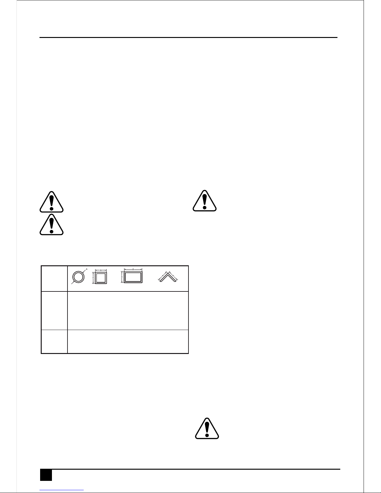
Cutting capacity
The wide vise opening and high pivot point provide cutting
capacity for many large pieces. Use the cutting capacity
chart to determine total maximum size of cuts that can be
made with a new wheel.
Caution: Certain large, circular or irregularly
shaped objects may require additional
holding means if they cannot be held
securely in vise.
Caution: do not cut magnesium with this tool.
Maximum cutting capacity
Note: Capacity shown on chart assumes no wheel wear and
optimum fence position.
Use
Standard equipment
• 355mm Metal Cutting Abrasive Wheel
• 1 Wheel Wrench
• 1 Instruction manual
To carry (fig. 1)
Fold down unit to position where you can carry the saw.
Push in lock pin (X) to lock arm down.
Unlocking (fig. 1)
To unlock tool and raise head, depress motor arm slightly
and pull lock pin (X) out. Motor arm will then pivot upward.
Spark deflector adjustment (fig. 1)
To best deflect sparks away from surrounding persons and
materials, loosen the screw (A), adjust the spark deflector
(B) and then retighten screw. Do not allow cordset to come
into contact with deflector or sparks as damage to cordset
may occur.
Depth stop (fig. 1)
Depth stop is set at the factory for a new 14" wheel to
prevent wheel from cutting into the supporting surface.To
allow more depth of cut, use the flat wrench provided (F) to
loosen the depth stop bolt (L) and raise bolt todesired height
and then turn jam nut (L) clockwise until seated firmly on the
casting. Securely tighten the depth stop bolt before use.
Caution: When changing to a new wheel,
readjust epth stop to original position to prevent
cutting intosupporting surface.
Trigger switch (fig. 1)
To start the tool, depress the trigger switch (M). To turn the
tool off, release the trigger switch. Keep hands and material
from wheel until it has coasted to a stop.To prevent
unauthorized use of tool, install a standard padlock (not
included) into the padlock hole (N) located inthe trigger.
Material clamping and supporting
• Angles are best clamped and cut with both legs resting
against base.
• A spacer block slightly narrower than the work piece can
be used to increase wheel utilization (Fig. 2).
• Long work pieces must be supported by a block so it will
be level with top of base (Fig. 3). The cut off end should
be free to fall downward to avoid wheel binding.
Vise operation (fig. 4)
The vise (E) has a quick-travel feature. To release the vise
when it is clamped tightly, turn the crank (G)
counterclockwise one or two times to remove clamping
pressure. Lift vise lever (H) up. Pull crank assembly out as
far asdesired. Vise may be pushed forward into work without
cranking. Lower vise lever (H) then tighten vise (E) onwork
by using crank (G).
Fence operation (fig. 5, 6)
Caution: Turn off and unplug the tool before
making any adjustments or removing or
installing attachments or accessories. Be
sure the trigger switch is in the OFF position.The fence
(D) can be adjusted two ways: to change desired cutting
angle and to change spacing between the fence and vise.
A x B
Workpiece
Shape:
90°
Cutting
Angle
45°
Cutting
Angle
A = 4-7/8"
(125mm)
A= 4-1/2"
(115mm)
A = 4-1/2"
(115mm)
A = 3-13/16"
(98mm)
4-1/2" x 5-1/8"
(115mm x 130mm)
4" x 7-5/8"
(102mm x 188mm)
3" x 7-3/8"
(76mm x 229mm)
4-1/2" x 3-13/16"
4-1/8" x 3-3/4"
(105mm x 95mm)
A = 4-1/2" x 5-3/8"
(115mm x 137mm)
A = 3-13/16"
3-3/4"
(95mm)
ENGLISH (Original instructions)
Page 7

7
To change the desired cutting angle
Use the wrench provided to loosen (do not remove) the two
fence bolts (O). Align the desired angle indicator line with
theslot line in the base (C). Securely tighten both fence bolts
before use. For more accurate square cuts, disconnect the
power supply, loosen the two fence bolts, push arm down
until wheel extends into base. Place a square against
thewheel and adjust fence against the square. Securely
tighten both fence bolts before use. When making a miter
cut, the vise (E) may not clamp securely, depending on the
thickness of the workpiece and the miter angle. Other aids
(such as spring, bar or C-clamps) will be necessary to
secure the work piece to the fence when making these cuts.
To change spacing between the fence and vise
Using the wrench provided, loosen and remove the two
fence bolts (O). Adjust the fence (D) to desired
locations.Insert both fence bolts in provided locations.
Securely tighten both fence bolts before use.
Removal and installation of wheels (fig. 7, 8)
Caution: Turn off and unplug the tool before
making any adjustments or removing or
installin gattachments or accessories. Be
sure the trigger switch is in the OFF position. Do not
make any adjustment while the wheel is in motion. Do not
make any adjustment while chop saw is plugged into power
supply.
1. Push in spindle lock (K) and rotate wheel (I) by hand
until wheel lock lever engages slot in inside flange(Q) to
lock wheel. Loosen the bolt (R) counterclockwise in the
center of the abrasive wheel with the 8mm hex wrench
(F). Bolt has right-hand thread.
2. Remove the bolt (S), washer (R), outside flange (T) and
old wheel (I).
3. Make sure flange surfaces are clean and flat. Install the
new abrasive wheel by reversing the above steps.
4. Do not overtighten bolt.
Warning: Check the work surface that the chop
saw rests on when replacing with a new
abrasive wheel. Itis possible that the wheel may
contact ANY ITEMS OR STRUCTURE THAT EXTENDS
ABOVE work surface (under the base) when the arm is fully
lowered.
Operation tips for more accurate cuts
• Allow the wheel to do the cutting. Excessive force will
cause the wheel to glaze reducing cutting efficiency
and/or to deflect causing inaccurate cuts.
• Properly adjust fence angle.
• Make sure material is laying flat across base.
• Properly clamp material to avoid movement and
vibration.
Motor brush inspection and replacement (fig.9)
Warning:Turn off and unplug the tool. Be sure
the trigger switch is in the OFF position.
Brushes should be regularly inspected for wear.
To inspect brushes, unscrew the two end cap screws (V) and
remove end cap (W). Remove brush cap (Y). Brushes (X)
should slide freely in brush box.
If brushes are worndown to .3" (8mm) as shown in Figure 9
they should be replaced. To reinstall, push new brush back
into brushbox. If replacing existing brush, maintain same
orientation as when removed. Replace the brush cap (do not
overtighten). Replace end cap and two screws. Tighten
securely.
Accessories
The performance of any power tool is dependent upon the
accessory used. STANLEY accessories areengineered to
high quality standards and are designed to enhance the
performance of power tool.
Note: Accessory must be rated for use at speed
equal to or higher than nameplate RPM of tool
with which it is being used.
Caution: The use of any other accessory not recommended
for use with this tool could be hazardous.Use only
high-strength Type 1 organic bonded wheels rated 4100 rpm
or higher. Recommended accessories for use with your tool
are available at extra cost from your local dealer or
authorized service center.
(Original instructions) ENGLISH
Page 8

8
Maintenance
Your STANLEY power tool has been designed to operate
over a long period of time with a minimum of
maintenance.Continuous satisfactory operation depends
upon proper tool care and regular cleaning.Your tool is not
user-serviceable. Take the tool to an authorized STANLEY
repair agent. This tool should be serviced at regular
intervals or when showing a noticeable change in
performance.
Lubrication
STANLEY power tools are properly lubricated at the factory
and are ready for use. Tools should be re-lubricated
regularly , depending on usage. This lubrication should only
be attempted by trained power tool repair persons, such as
those at STANLEY service centers or by other qualified
service personnel. Closed-type, grease-sealed ball bearings
are used throughout. These bearings have sufficient
lubricationpacked in them at the factory to last the life of the
chop saw.
Cleaning
Warning: unplug the tool before you use a cloth
to clean the housing.With the motor running,
blow dirt and dust out of all air vents with dry air
at least once a week. Wear safety glasses when performing
this. Exterior plastic parts may be cleaned with a damp cloth
and mild detergent. Although these parts are highly solvent
resistant, NEVER use solvents.
Blowing dust and grit out of the main housing by means of
an air hose is recommended and may be done as often as
dirt is seen collecting in and around the air vents. Always
wear proper eye and respiratory protection.
Tool care
Avoid overloading the machine.Overloading will result in a
considerable reduction in speed and efficiency and the unit
will become hot. In this event,run the machine at no load for
a minute or two until cooled to normal working temperature
by the built in fan. Switching your machine on and off whilst
under load will considerably reduce the life of the switch.
Important
To ensure product SAFETY and RELIABILITY, repairs,
maintenance and adjustment (other than those listed in this
manual) should be performed by authorized service centers
or other qualified organizations, always-using identical
replacement parts. Unit contains no user serviceable parts
inside.Blowing dust and grit out of the main housing by
means of an air hose is recommended and may be done as
often as dirt is seen collecting in and around the air vents.
Always wear proper eye and respiratory protection.
Note: Unit may be converted to a 3-wire twist lock cord set
at an authorized service center.
Notes
• STANLEY's policy is one of continuous improvement to
our products and, as such, we reserve the right
tochange product specifications without prior notice.
• Standard equipment and accessories may vary by
country.
• Product specifications may differ by country.
• Complete product range may not be available in all
countries.
• Contact your local STANLEY dealers for range
availability.
ENGLISH (Original instructions)
Page 9

Protecting the environment
Separate collection. This product must not be
disposed of with normal household waste.
Should you find one day that your STANLEY product needs
replacement, or if it is of no further use to you, do not
dispose of it with household waste. Make this product
available for separate collection.
Separate collection of used products and packaging
allows materials to be recycled and used again.
Re-use of recycled materials helps prevent
environmental pollution and reduces the demand for raw
materials.
Local regulations may provide for separate collection of
electrical products from the household, at municipal waste
sites or by the retailer when you purchase a new product.
STANLEY provides a facility for the collection and recycling
of STANLEY products once they have reached the end of
their working life. To take advantage of this service please
return your product to any authorised repair agent who will
collect them on our behalf.
You can check the location of your nearest authorised repair
agent by contacting your local STANLEY office at the
address indicated in this manual. Alternatively, a list of
authorised STANLEY repair agents and full details of our
after-sales service and contacts are available on the Internet
at: www.2helpU.com
9
Technical data
Specifications STSC2135
POWER W 2100
NO-LOAD SPEED /min 3800
MAX. DIAMETER mm 355
Weight kg 15.5
STANLEY declares that these products described under
"technical data" are in compliance with:
2006/42/EC, EN 61029-1, EN 61029-2-10
These products also comply with Directive
“2004/108/EC (until 19.04.2016),
2014/30/EU (from 20.04.2016)” and 2011/65/EU.
For more information, please contact STANLEY at the
following address or refer to the back of the manual.
The undersigned is responsible for compilation of the
technical file and makes this declaration on behalf of
STANLEY.
R.Laverick
Engineering Manager
STANLEY , Europe, Egide Walschaertsstraat14-18,
2800 Mechelen, Belgium
01.2015
EC declaration of conformity
MACHINERY DIRECTIVE
STSC2135
LpA (sound pressure) dB(A) 95,5
K
pA
(sound pressure uncertainty) dB(A) 3
LWA (sound power) dB(A) 105,5
KWA (sound power uncertainty) dB(A) 3
Vibration emission value a
h
a
h
= m/s² 4.3
Uncertainty K = m/s² 1.5
(Original instructions) ENGLISH
Page 10

10
Service Information
STANLEY offers a full network of company-owned and
authorized service locations. All STANLEY Service Centers
are staffed with trained personnel to provide customers with
efficient and reliable power tool service. For more information
about our authorized service centers and if you need
technical advice, repair, or genuine factory replacement
parts, contact the STANLEY location nearest you.
Two years full warranty
If your STANLEY product becomes defective due to faulty
materials or workmanship within 24 months from the date of
purchase, STANLEY guarantees to replace all defective
parts free of charge or – at our discretion – replace the unit
free of charge provided that:
• The product has not been misused and has been used in
accordance with the instruction manual.
• The product has been subject to fair wear and tear;
• Repairs have not been attempted by unauthorised
persons;
• Proof of purchase is produced.
• The STANLEY product is returned complete with all
original components
If you wish to make a claim, contact your seller or check the
location of your nearest authorised STANLEY repair agent in
the STANLEY catalogue or contact your local STANLEY
office at the address indicated in this manual. A list of
authorised STANLEY repair agents and full details of our
after sales service is available on the internet
at:www.stanleytools.com
ENGLISH (Original instructions)
Page 11

11
İŞ PARÇASININ ÇAPI
DESTEK PARÇASININ GENİŞLİĞİ
DESTEK PARÇASI
E
F
X
.3 "
(8m m)
ŞEKİL A
ŞEKİL I
E
H
I
F
P
İLERİ
ŞEKİL G
L
ŞEKİL H
R
J
U
T
S
Y
W
V
K
J
F
H
I
L
N
o
A
M
G
X
E
D
KESİLMİŞ UÇ
TAHTA PARÇA
C
B
F
P
A
E
ŞEKİL F
P
E
AD
ŞEKİL B
ŞEKİL C
ŞEKİL D ŞEKİL E
(Çevirisi orijinal talimatlardan yapılmıştır) TÜRKÇE
Page 12

12
Kullanım amacı
Stanley profil kesme makineniz kesim uygulamaları için
tasarlanmıştır.
Genel güvenlik kuralları
Uyarı! Tüm talimatları okuyun. Aşağıda belirtilen tüm
talimatların herhangi birisine uyulmaması elektrik çarpması,
yangın ve/veya ciddi yaralanma riskine neden olabilir.
Aşağıda yer alan uyarılardaki «elektrikli alet» terimi şebeke
elektriğiyle (kablolu) veya akü/pille (şarjlı) çalışan elektrikli
aletinizi ifade etmektedir.
BU TALİMATLARI SAKLAYIN.
1. Çalışma alanı
a. Çalışma alanını temiz ve aydınlık tutun. Karışık ve
karanlık alanlar kazaya davetiye çıkartır.
b. Elektrikli aletleri, yanıcı sıvılar, gazlar ve tozların
bulunduğu yerler gibi yanıcı ortamlarda
çalıştırmayın. Elektrikli aletler, toz veya dumanları
ateşleyebilecek kıvılcımlar çıkartır.
c. Bir elektrikli aleti çalıştırırken çocuklardan ve
etraftaki kişilerden uzak tutun. Dikkatinizi dağıtıcı
şeyler kontrolü kaybetmenize neden olabilir.
2. Elektrik güvenliği
a. Elektrikli aletlerin fişleri prizlere uygun olmalıdır. Fiş
üzerinde kesinlikle hiçbir değişiklik yapmayın.
Topraklı elektrikli aletlerde hiçbir adaptör fişi
kullanmayın. Değiştirilmemiş fişler ve uygun prizler
elektrik çarpması riskini azaltacaktır.
b. Borular, radyatörler, ocaklar ve buzdolapları gibi
topraklanmamış yüzeylerle vücut temasından
kaçının. Vücudunuzun topraklanması halinde yüksek bir
elektrik çarpması riski vardır.
c. Elektrikli aletleri yağmura maruz bırakmayın veya
ıslatmayın. Elektrikli alete su girmesi elektrik çarpması
riskini arttıracaktır.
d. Elektrik kablosunu uygun olmayan amaçlarla
kullanmayın. Elektrikli aleti kesinlikle kablosundan
tutarak taşımayın, çekmeyin veya prizden
çıkartmayın. Kabloyu sıcaktan, yağdan, keskin
kenarlardan veya hareketli parçalardan uzak tutun.
Hasarlı veya dolaşmış kablolar elektrik çarpması riskini
arttırır.
e. Elektrikli bir aleti açık havada çalıştırıyorsanız, açık
havada kullanıma uygun bir uzatma kablosu
kullanın. Açık havada kullanıma uygun bir kablonun
kullanılması elektrik çarpması riskini azaltır.
f. Eğer bir elektrikli aletin nemli bir bölgede
çalıştırılması zorunluysa, bir artık akım aygıtı (RCD)
korumalı bir kaynak kullanın. Bir RCD kullanılması
elektrik şoku riskini azaltır.
Not: «Artık Akım Aygıtı (RCD)» tanımı, «Kaçak Akım
Koruma Cihazı (GFCI)» veya «Toprak Kaçağı Devre Kesici
(ELCB)» tanımları ile değiştirilebilir.
3. Kişisel güvenlik
a. Elektrikli bir aleti kullanırken her zaman dikkatli olun,
yaptığınız işe yoğunlaşın ve sağduyulu davranın.
Elektrikli bir aleti yorgunken veya ilaç ya da alkolün
etkisi altındayken kullanmayın. Elektrikli aletleri
kullanırken bir anlık dikkatsizlik ciddi kişisel
yaralanmayla sonuçlanabilir.
b. Kişisel koruyucu ekipmanları kullanın. Daima
koruyucu gözlük takın. Koşullara uygun toz maskesi,
kaymayan güvenlik ayakkabıları, baret veya kulaklık gibi
koruyucu donanımların kullanılması kişisel yaralanmaları
azaltacaktır.
c. Aletin istem dışı çalıştırılmasını engelleyin. Elektrik
şebekesine bağlamadan önce aletin kapalı
olduğundan emin olun. Aleti, parmağınız düğme
üzerinde bulunacak şekilde taşımak veya açık
konumdaki elektrikli aletleri elektrik şebekesine bağlamak
kazaya davetiye çıkartır.
d. Elektrikli aleti açmadan önce tüm ayarlama
anahtarlarını çıkartın. Elektrikli aletin hareketli bir
parçasına takılı kalmış bir anahtar kişisel yaralanmaya
neden olabilir.
e. Ulaşmakta zorlandığınız yerlerde kullanmayın. Daima
sağlam ve dengeli basın. Bu, beklenmedik durumlarda
elektrikli aletin daha iyi kontrol edilmesine olanak tanır.
f. Uygun şekilde giyinin. Bol elbiseler giymeyin ve takı
takmayın. Saçınızı, elbiselerinizi ve eldivenlerinizi
hareketli parçalardan uzak tutun. Bol elbiseler ve
takılar veya uzun saç hareketli parçalara takılabilir.
g. Eğer kullandığınız üründe toz emme ve toplama
özellikleri olan ataşmanlar varsa bunların bağlı
olduğundan ve doğru şekilde kullanıldığından emin
olun. Bu ataşmanların kullanılması tozla ilgili tehlikeleri
azaltabilir.
4. Elektrikli aletlerin kullanımı ve bakımı
a. Elektrikli aleti zorlamayın. Uygulamanız için doğru
elektrikli aleti kullanın. Doğru elektrikli alet, belirlendiği
kapasite ayarında kullanıldığında daha iyi ve güvenli
çalışacaktır.
b. Düğme açmıyor ve kapatmıyorsa elektrikli aleti
kullanmayın. Tetikle kontrol edilemeyen tüm elektrikli
aletler tehlikelidir ve tamir edilmesi gerekmektedir.
c. Herhangi bir ayarlama, aksesuar değişimi veya
elektrikli aletlerin saklanması öncesinde fişi güç
kaynağından çekin ve/veya aküyü elektrikli aletten
ayırın. Bu tür önleyici güvenlik tedbirleri aletin istem
dışı olarak çalıştırılması riskini azaltacaktır
TÜRKÇE (Çevirisi orijinal talimatlardan yapılmıştır)
DUMMY TEXT
Page 13

13
d. Elektrikli aleti, çocukların ulaşamayacağı yerlerde
saklayın ve elektrikli aleti tanımayan veya bu
talimatları bilmeyen kişilerin elektrikli aleti
kullanmasına izin vermeyin. Elektrikli aletler, eğitimsiz
kullanıcıların elinde tehlikelidir.
e. Elektrikli aletleri iyi durumda muhafaza edin.
Hareketli parçalardaki hizalama hatalarını ve
tutuklukları, parçalardaki kırılmalar ve elektrikli
aletin çalışmasını etkileyebilecek tüm diğer koşulları
kontrol edin. Hasarlı ise, elektrikli aleti kullanmadan
önce tamir ettirin. Kazaların çoğu, elektrikli aletlerin
bakımının yeterli şekilde yapılmamasından kaynaklanır.
f. Elektrikli aleti, aksesuarlarını ve aletin diğer
parçalarını kullanırken bu talimatlara mutlaka uyun
ve çalışma ortamının koşullarını ve yapılacak işin ne
olduğunu göz önünde bulundurun. Elektrikli aletin
öngörülen işlemler dışındaki işlemler için kullanılması
tehlikeli durumlara neden olabilir.
5. Servis
a. Elektrikli aletinizi, sadece orijinal yedek parçaların
kullanıldığı yetkili servise tamir ettirin. Bu, elektrikli
aletin güvenliğinin muhafaza edilmesini sağlayacaktır.
Profil kesmeler için ek güvenlik talimatları
• Her zaman koruyucu gözlük ve solunum korumasını
kullanın.
• Kullanmadan önce, kesme diskinde herhangi bir
çatlak ya da yarık olup olmadığını kontrol edin.
Üzerinde çatlak ya da yarık olan kesme diskini atın.
Aletin düşmüş olabileceğini düşünüyorsanız her
zaman kesme diski kontrol edin. Çatlaklar veya
yarıklar disk kırılmasına neden olabilir.
• Yeni veya değiştirilmiş diski taktıktan sonra veya
diskin durumundan emin değilseniz aleti iyi
korunmuş bir alana yerleştirin ve bir dakika boyunca
çalışmasına izin verin. Diskte fark edilmemiş bir çatlak
ya da yarık varsa, bir dakikadan daha kısa bir süre
içinde disk kırılacaktır. Disk ile aynı hizada insanlar
varsa, aleti asla çalıştırmayın. Bu koşul kullanıcı için de
geçerlidir.
• Çalışma esnasında, diskin yerinden oynamasını
engelleyin veya diski zorlamayın. Aksi olursa, aleti
durdurun ve diskinde herhangi bir çatlak ya da yarık olup
olmadığını kontrol edin.
• Bu kılavuzdaki prosedürü izleyerek periyodik olarak
profil kesmenizi temizleyin.
Kullanim sirasinda
• Testere bıçağı bloke olur • Eğer, derhal aleti kapatın ve
fişini çekin; ancak o zaman kamalı parçasını kaldırmak
• sıkışma veya elektrik veya mekanik arıza durumunda,
derhal aleti kapatın ve fişini çekin
• Disk muhafazası veya tabanı çıkartmayın.
• MALZEMEYİ SABİTLEMEK İÇİN HER ZAMAN
MENGENE VEYA BAŞKA BAĞLANTI
EKİPMANLARINI KULLANIN. Yay, pala veya C-kelepçe
gibi diğer yardımcı ekipmanlar iş parçasının boyutlara ve
şekillere uygun olmalıdır. Bu kelepçelerin seçim ve
yerleştirme sırasında dikkatli olun ve bir asıl kesim
yapmadan önce deneme çalışmasını yapın.
• Sadece 355 mm (14") 4100 dev/dak veya daha yüksek
nominal hıza sahip olan tip 1 diskleri kullanın.
• Ellemeden önce kesilen parçaların soğumasına izin
verin.
• Ahşap veya plastik malzemeleri kesmeye kalkışmayın.
• ASLA MAGNEZYUM MALZEMELER KESMEYİN.
• Profil kesmeyi iyi havalandırılan bir alanda kullanın.
• Tabandan herhangi parça çıkartmadan önce kesme
profilinizi kapatın.
• ELEKTRİĞE BAĞLI MALZEMELERİ KESMEYİN.
• Bu aletle dairesel kesim bıçaklarını veya diğer dişli
bıçakları kullanmayın. Ciddi yaralanmaya neden
olabilir.
• ALETİ YANICI SIVILAR VEYA GAZLARIN YANINDA YA
DA TOZLU ALANLARDA KULLANMAYIN. Kesmeden
kaynaklanan kıvılcım veya sıcak yonga ya da yaylı motor
fırçaları, yanıcı maddelerin tutuşmasına neden olabilir.
• Aşındırıcı diskin kenarını taşlama işlemleri için
kullanmayın. Bu büyük ölçüde diski zayıflatır ve tehlikeli
bir duruma yol açabilir. Disk aletten çıkabilir.
Uyarı: Aleti kullanırken koruyucu kulaklık
takın. Bazı koşullarda ve kullanım süresine göre
bu aletin gürültüsü işitme kaybına neden olabilir.
Uyarı: Kıvılcım yön saptırıcısı ısınacaktır.
Sıcakken dokunmaktan ve ayarlamaktan
kaçının. Kablo ve malzemeleri kıvılcım yön
saptırıcısından uzak tutun.
• Zımpara, kesme, taşlama, delme ve diğer inşaat
faaliyetleri sırasında toz ile uzun süreli temastan
kaçının. Koruyucu giysiler giyin ve açıkta kalan
yerlerinizi sabun ve su ile yıkayın. Tozun ağıza, göze
girmesi veya cilt üzerinde bulunması zararlı kimyasallar
emilimini teşvik edebilir.
(Çevirisi orijinal talimatlardan yapılmıştır) TÜRKÇE
DUMMY TEXT
Page 14

14
Uyarı: Her zaman NIOSH / OSHA tarafından
onaylı toz maruziyeti için uygun bir solunum
korumasını kullanın. Yüzünüzü ve vücudunuzu
uçan parçacıklardan uzakta tutun. Sizin rahatlığınız ve
güvenliğiniz için, ağır hizmet tipi 14"(355mm) profil kesmeniz
üzerinde aşağıdaki uyarılar vardır:
Güvenli bir çalışma için kullanım kılavuzunu
okuyun.
• Dişli diskleri kullanmayın.
• Sadece 4100 dev/dak veya daha yüksek devirli
güçlendirilmiş diskler kullanın.
• Servis işlemleri sırasında sadece orijinal yedek
parçaları kullanının.
• Her zaman göz koruması takın, muhafazalar kullanın,
çalışma parçasını mengene ile sabitleyin, uygun
soluma koruması kullanın.
• Aleti ıslak yerlerde kullanmayın veya yağmura maruz
bırakmayın.
• Sadece maksimum kalınlığı 2,8 mm olan ve
maksimum çapı 355 mm olan profil kesme diski
kullanın.
Titreşim
Teknik veriler ve uygunluk beyanatı içerisinde belirtilen
titreşim emisyon değerleri EN61029 tarafından belirlenen
standart bir test yöntemine uygun olarak ölçülmektedir ve
diğer bir aletle karşılaştırma yaparken kullanılabilir. Beyan
edilen titreşim emisyon değeri aynı zamanda maruz
kalmanın önceden değerlendirilmesinde de kullanılabilir.
Uyarı! Elektrikli aletin mevcut kullanımı sırasındaki titreşim
emisyon değeri, aletin kullanım yöntemine bağlı olarak,
beyan edilen değere göre farklılık sergileyebilir. Titreşim
düzeyi belirlenen seviyenin üzerinde artış gösterebilir.
İşyerinde düzenli olarak elektrikli alet kullanan çalışanları
korumak amacıyla 2002/44/EC tarafından getirilen elektrik
güvenliği önlemlerini belirlemek üzere titreşime maruz
kalmayı değerlendirirken, çalışma döngüsü içerisinde
örneğin aletin kapalı olduğu ve aktif durumda olmasının yanı
sıra boşta çalıştığı zamanlar gibi, bütün zaman dilimleri dahil
olmak üzere mevcut kullanım durumu ve aletin kullanım şekli
göz önünde bulundurularak değerlendirilmelidir.
Elektrik güvenliği
Uyarı! Elektrik kablosu hasarlı ise, bir tehlike oluşmasını
önlemek için üretici ya da yetkili Stanley Servis Merkezi
tarafından değiştirilmelidir. Elektrik kablosu Stanley yetkili
servisi haricinde değiştirilirse, garanti geçerli olmayacaktır.
Açıklama (Şekil 1, 4)
A. Kıvılcım yön saptırıcısı vidası
B. Kıvılcım yön saptırıcısı
C. Taban
D. Kesme kılavuzu
E. Mengene
F. Düz anahtar
G. Döndürme kolu
H. Mengene kolu
I. Disk
J. Muhafaza
K. Mil kilidi
L. Derinlik ayarı cıvata ve emniyet somunu
M. Açma/kapama tetik düğmesi
V ........ Volt
A ........ Amper
Hz ....... Hertz
W ........ Vat
dak ..... dakika
.....
.....
boş .......
......
....
....
.../min..
7. Alet üzerindeki etiketler
Alet üzerinde aşağıdaki semboller bulunabilir:
Kullanım
Kılavuzunu
Okuyun
Koruyucu
Gözlük kullanın
Kulaklık
Kullanın
Alternatif
Akım
Direkt
Akım
Yüksüz
Hız
Sınıf II
İnşaat
Topraklama
Terminal
Güvenlik
uyarısı
Sembolü
Dakikada
devir veya
gel git sayısı
Tarih kodu konumu
İmalat yılını da içeren Tarih Kodu gövdeye basılıdır.
Örnek:
2014 XX JN
İmalat Yılı
TÜRKÇE (Çevirisi orijinal talimatlardan yapılmıştır)
Page 15

15
N. Asma kilit deliği
O. Kesme kılavuzu cıvataları
X. Kilit pimi
Şebeke gerilimi
Her zaman şebeke geriliminin aletin üretim etiketinde
belirlenmiş değerlere uyup uymadığını kontrol edin. %
10'dan daha fazla bir gerilim azalması güç kaybına ve aşırı
ısınmaya neden olacaktır.
Kesme kapasitesi
Geniş açılan mengene ve yüksek dönme noktası birçok
geniş malzemenin kesilmesi için gerekli kapasiteyi sağlar.
Yeni bir diskle kesilebilecek maksimum kesme ölçüsünü
belirlemek için kesme kapasitesi tablosunu kullanın.
Uyarı: Bazı geniş, dairesel veya düz olmayan
şekilli nesneler, mengene ile güvenli bir
şekilde sabitlenemeyebilir ve ek tutma
desteğine ihtiyaç duyabilir.
Uyarı: Bu aletle magnezyum kesmeyin.
Maksimum kesme kapasitesi
Not: Tabloda gösterilen kapasite aşınmamış disk ve en
uygun mengene konumuna göre kabul edilmiştir.
Kullanımı
tandart ekipman
• 355mm Metal Kesme Aşındırıcı Diski
• Disk anahtarı
• Kullanım kılavuzu
Taşıma (Şekil 1)
Aleti taşımak için ilk önce alet katlanmalıdır. Kilit pimi (X)
yardımı ile profil kesme kafasını sabitleyin.
Kilidi Açma (Şekil 1)
Aletin kilidini açmak ve kafasını kaldırmak için motor
gövdesine hafif olarak basın ve kilit pimini (X) çıkartın. Motor
gövdesi yukarı doğru dönecektir.
Kıvılcım Yön Saptırıcısının Ayarlanması (Şekil 1)
Çevredeki kişiler ve malzemelerden kıvılcımları daha iyi
saptırmak için vidayı (A) gevşetin, kıvılcım yön saptırıcısını
(B) ayarlayın ve ardından vidayı sıkın. Kablonun saptırıcı
veya kıvılcım ile temas etmesine izin vermeyin, hasar
oluşabilir.
Derinlik Ayarı (Şekil 1)
Derinlik ayarı, destek yüzeyinin kesmesini önlemek için yeni
bir 355 mm (14 ") disk için fabrikada ayarlanmıştır. Kesme
derinliği ayarlamak için aletle verilen düz anahtarı (F)
kullanarak derinlik ayarı cıvatasını (L) gevşetin, cıvatayı
istenilen yüksekliğe kaldırın ve emniyet somununu (L) saat
yönünde sonuna kadar sıkın. Aleti kullanmadan önce derinlik
ayarı cıvatasını iyice sıkın.
Diski değiştirirken derinlik ayarını, destek
yüzeyinin kesmesini önlemek için daima orijinal
konumuna ayarlayın.
Açma/Kapama Tetik Düğmesi (Şekil 1)
Aleti açmak için, açma/kapama tetik düğmesine (M) basın.
Aleti kapatmak için, açma/kapama tetik düğmesini bırakın.
Alet tamamen durana kadar elleri ve malzemeleri diskten
uzak tutun. Aletin izinsiz kullanılmasını önlemek için standart
bir asma kilidi (alet ile birlikte verilmemektedir), tetik
mekanizmasında bulunan asma kilit deliğine (N) takın.
Malzeme Sıkıştırma ve Destekleme
• Açılı kesimler her iki köşe de taban üzerinde
desteklendiğinde en iyi şekilde sıkıştırılır ve kesilir.
• Kesim kapasitesini arttırmak için, çalışma parçasının
altına bir destek parçası yerleştirin. Destek parçası,
çalışma parçasından biraz daha dar olmalıdır (Şekil 2).
• Uzun çalışma parçalarını taban yüzeyi ile hizalayarak bir
parça tahta kullanarak destekleyin (Şekil 3). Diskin
sıkışmasını önlemek için kesilmiş uç serbest olarak aşağı
düşmelidir.
Mengene Kullanımı (Şekil 4)
Mengene (E), hızlı hareket özelliğine sahiptir. Fazla sıkılmış
mengeneyi serbest bırakmak için döndürme kolunu (G) bir
veya iki tur saat yönünün tersine çevirin ve mengeneyi
gevşetin. Mengene kolunu (H) yukarı kaldırın. Döndürme
kolunu istediğiniz kadar dışarı çekin. Mengene, döndürme
kolunu kullanmadan çalışılan parçaya doğru itilebilir.
Mengene kolunu (H) aşağı indirin ve mengeneyi (E)
döndürme kolunu (G) kullanarak çalışılan parça üzerinde
sıkın.
A x B
Çalışma
parçası
şekli:
90°
Kesme
Açısı
45°
Kesme
Açısı
A = 4-7/8"
(125mm)
A= 4-1/2"
(115mm)
A = 4-1/2"
(115mm)
A = 3-13/16"
(98mm)
4-1/2" x 5-1/8"
(115mm x 130mm)
4" x 7-5/8"
(102mm x 188mm)
3" x 7-3/8"
(76mm x 229mm)
4-1/2" x 3-13/16"
4-1/8" x 3-3/4"
(105mm x 95mm)
A = 4-1/2" x 5-3/8"
(115mm x 137mm)
A = 3-13/16"
3-3/4"
(95mm)
(Çevirisi orijinal talimatlardan yapılmıştır) TÜRKÇE
Page 16

16
Kesme Kılavuzu Kullanımı (Şekil 5, 6)
Uyarı: Herhangi bir ayarlama veya
aksesuarları takıp çıkarmadan önce aleti
kapatın ve fişini çekin. Tetik düğmesinin
kapalı konumda olduğunu kontrol edin.
Kesme kılavuzu (D) iki şekilde ayarlanabilir: istenilen kesim
açısının değiştirerek ve kesme kılavuzu ve mengene
arasındaki aralığı değiştirerek.
İstenilen Kesme Açısının Değiştirilmesi
Aletle birlikte verilen anahtarı kullanarak iki adet kesme
kılavuzu cıvatasını (O) gevşetin (ama çıkartmayın). İstenilen
açı gösterge çizgisini taban (C) üzerindeki bölme ile
hizalayın. Aleti kullanmadan önce her iki kesme kılavuzu
cıvatasını sağlam bir şekilde sıkın. Daha hassas köşeli
kesimler için, aleti güç kaynağından ayırın, iki kesme
kılavuzu cıvatasını gevşetin ve disk tabanına ulaşına kadar
kesme kafasını aşağı itin. Diskin karşısına bir köşebent
yerleştirin ve kesme kılavuzunu köşebente göre ayarlayın.
Aleti kullanmadan önce her iki kesme kılavuzu cıvatasını
sağlam bir şekilde sıkın. Gönye kesimleri yaparken
mengene (E), çalışılan parça kalınlığına ve gönye açısına
göre sabitlenmelidir. Böyle kesimler yaparken çalışılan
parçayı kesme kılavuzuna sabitlemek için başka yardımcı
ekipmanlar da gerekebilir (yay, pala, C-kelepçe gibi).
Kesme Kılavuzu Ve Mengene Arasındaki Aralığı
Değiştirilmesi
Aletle birlikte verilen anahtarı kullanarak iki adet kesme
kılavuzu cıvatasını (O) gevşetin ve çıkartın. Kesme
kılavuzunu (D) istenilen pozisyonuna ayarlayın. Sunulan
yerlere her iki kesme kılavuzu cıvatalasını yerleştirin. Aleti
kullanmadan önce her iki kesme kılavuzu cıvatasını sağlam
bir şekilde sıkın.
Kesme Diskinin Takılması ve Çıkartılması (Şekil 7, 8)
Uyarı: Herhangi bir ayarlama veya
aksesuarları takıp çıkarmadan önce aleti
kapatın ve fişini çekin. Tetik düğmesinin
kapalı konumda olduğunu kontrol edin. Disk hareket
ederken herhangi bir ayar yapmayın. Profil kesme elektrik
prizine takılıyken, herhangi bir ayarlamayı yapmayın.
1. Kesme diskini sabitleyin. Bunun için mil kilidine (K)
basın ve diskin (I) sabitleme kolu iç flanşın (Q)
üzerindeki yuvaya oturana kadar elle çevirin. Aşındırıcı
diskin merkezinde bulunan cıvatayı (R) 8 mm altıgen
anahtarı (F) kullanarak saatin ters yönünde çevirerek
gevşetin. Cıvata sağ oluğa sahiptir.
2. Cıvatayı (R), pulu (S), dış flanşı (T) ve eski kesme
diskini (I) çıkartın.
3. Flanş yüzeylerinin temiz ve düz olduğundan emin olun.
Yukarıdaki adımları tersten izleyerek teni kesme diskini
takın.
4. Cıvatayı aşırı sıkmayın.
Uyarı: Yeni aşındırıcı diski takarken profil
kesmenin yerleştirildiği çalışma yüzeyini kontrol
edin. Kesme kafası tamamen indirilmiş
olduğunda disk çalışma yüzeyinin üstünde
UZANAN (tabanın altında) HERHANGİ BİR ÖĞE YA DA
YAPI ile temas edebilir.
Daha Hassas Kesimler İçin Çalışma Tavsiyeleri
• Kesme diskine kesim yapmasına izin verin. Aşırı kuvvet
uygulanması diskin kesme verimliliğini azaltacak ve /
veya diskin saptırılmasına ve hatalı kesimlere neden
olacaktır.
• Kesme kılavuzu açısını doğru bir şekilde ayarlayın.
• Malzemenin taban üzerinde düz bir şekilde
yerleştiğinden emin olun.
• Hareket etmesini ve titreşimi önlemek için malzemeyi
sağlam bir şekilde sabitleyin.
Motor Kömürünün Kontrol Edilmesi ve Değiştirilmesi
(Şekil 9)
Uyarı: Aleti kapatın ve fişten çekin. Tetik
düğmesinin kapalı konumda olduğunu
kontrol edin. Kömürler düzenli olarak aşınma
durumu için kontrol edilmelidir. Kömürleri kontrol
etmek için arka kapaktaki iki vidayı (V) sökün ve arka kapağı
(W) çıkartın. Kömür kapağını (Y) sökün. Kömürler (X) kömür
yuvası içinde serbestçe kaymalıdır.
Eğer kömürler Şekil 9'da gösterildiği gibi 8mm'nin (3") altına
inecek şekilde aşınmışlarsa değiştirilmelidir. Yeniden takmak
için, yeni kömürü, kömür yuvasının içine itin. Eğer mevcut
kömürü yeniden takıyorsanız, çıkardığınız şekilde, aynı
yönde takın. Kömür kapağını yerine takın (gereğinden fazla
sıkmayın). Arka kapağı ve iki vidasını yerine takın. İyice
sıkın.
Aksesuarlar
Herhangi bir elektrikli aletin performansı kullanılan
aksesuarlara bağlıdır. STANLEY aksesuarları, yüksek kalite
standartlarına göre üretilmiş ve elektrikli aletinizin
performansını arttıracak şekilde tasarlanmıştır.
Not:
Aksesuarın nominal hızı, kullanıldığı
elektrikli alet üzerinde yazan maksimum hıza
eşit olmalı veya bundan yüksek olmalıdır.
Uyarı: Bu alet ile kullanılması önerilmeyen aksesuarların
kullanılması ciddi yaralanmaya yol açabilir. Sadece 4100
dev/dak veya daha yüksek bir değere sahip organik
bağlamalı yüksek dayanıklılığa sahip Tip 1 diskleri kullanın.
Aletinizle kullanılabilecek, tavsiye edilen aksesuarlar bedeli
karşılığı satış noktalarından temin edilebilir.
TÜRKÇE (Çevirisi orijinal talimatlardan yapılmıştır)
Page 17

17
Bakım
STANLEY elektrikli aletiniz minimum bakımla uzun bir süre
çalışacak şekilde tasarlanmıştır. Kesintisiz olarak
memnuniyet verici bir şekilde çalışması gerekli özenin
gösterilmesine ve düzenli temizliğe bağlıdır. Bu aletin servisi
kullanıcı tarafından yapılamaz. Aleti yetkili STANLEY
servisine götürün. Bu alet, belirli aralıklarla veya
performansında gözle görülür bir değişiklik gösterince
bakıma götürülmelidir.
Yağlama
STANLEY elektrikli el aletleri, fabrikada uygun bir şekilde
yağlanmıştır ve çalışmaya hazırdır. Aletler, kullanımına bağlı
olarak, düzenli bir şekilde yağlanmalıdır. Bu yağlama
sadece STANLEY servislerindeki gibi eğitimli elektrikli el
aleti tamir personeli tarafından yapılmalıdır. Aletin
tamamında kapalı tipte, yağ sızdırmaz bilyalı yataklar
kullanılmıştır. Bu yataklar, fabrikada profil kesmenin kullanım
ömrü boyunca yetecek miktarda yağla doldurulmuştur.
Temizleme
Uyarı: Aletin gövdesini bezle temizlemeden
önce fişini şebekeden çekin. Tüm hava
deliklerini, motor çalışırken haftada en az bir
kere kuru hava ile kir ve tozdan temizleyin. Bu uygulamayı
yaparken koruyucu gözlük takın. Dış plastik parçalar nemli
bir bezle ve yumuşak deterjanla silinebilir. Bu parçaların,
çözücüye karşı yüksek direnci olmasına rağmen, çözücü
maddeleri ASLA kullanmayın.
Havalandırma çıkışlarının içinde ve civarında toz birikmeye
başladığında, hortumla hava üfleyerek ana gövdenin toz ve
kirden temizlenmesi önerilir. Her zaman koruyucu gözlük ve
solunum korumasını kullanın.
Alet bakımı
Aşırı yüklemeden kaçının. Aşırı yüklenme hız ve verimliliğin
azalmasına neden olacak ve alet ısınacaktır. Bu durumda
dahili fan sayesinde normal çalışma sıcaklığına soğuyana
kadar bir ya da iki dakika boyunca makineyi yüksüz
çalıştırın. Aletinizi yük altında iken kapatmanız açma/kapama
düğmesinin ömrünü azaltacaktır.
Önemli
Alet EMNİYET GÜVENLİĞİ ve GÜVENİLİRLİK için bu
kılavuzda belirtilenler dışında tamir, bakım ve ayarlamaların
her zaman orijinal yedek parça kullanılarak, yetkili servisler
tarafından yapılması gerekmektedir. Aletin içinde bakımı
kullanıcı tarafından yapılabilecek herhangi bir parça yoktur.
Havalandırma çıkışlarının içinde ve civarında toz birikmeye
başladığında, hortumla hava üfleyerek ana gövdenin toz ve
kirden temizlenmesi önerilir. Her zaman koruyucu gözlük ve
solunum korumasını kullanın.
Not: Alet kablosu yetkili serviste üç telli kablo seti ile
değiştirilebilir.
Notlar
• STANLEY olarak, ürünlerimizi sürekli iyileştirme
politikası uyguladığımızdan, önceden haber vermeden
ürün özelliklerini değiştirme hakkını saklı tutarız.
• Standart ekipman ve aksesuarlar ülkeye göre değişebilir.
• Ürün özellikleri ülkelere göre farklı olabilir.
• Komple ürün çeşidi tüm ülkelerde geçerli olmayabilir.
• Ürün çeşidi durumu hakkında lütfen en yakın STANLEY
yetkili servisiyle temas kurun.
(Çevirisi orijinal talimatlardan yapılmıştır) TÜRKÇE
Page 18

18
Çevrenin korunması
Ayrı olarak atın. Bu ürün, normal evsel atıklarla
birlikte atılmamalıdır.
STANLEY ürününüzün değiştirilmesi gerektiğini düşünmeniz
veya artık kullanılamaz durumda olması halinde onu, evsel
atıklarla birlikte atmayın. Bu ürünü, ayrı olarak toplanacak
şekilde atın.
Kullanılmış ürünlerin ve ambalajların ayrı olarak
toplanması bu maddelerin geri dönüşüme sokularak
yeniden kullanılmasına olanak tanır. Geri dönüşümlü
maddelerin tekrar kullanılması çevre kirliliğinin önlenmesine
yardımcı olur ve ham madde ihtiyacını azaltır.
Yerel yönetmelikler, elektrikli ürünlerin evlerden toplanıp
belediye atık tesislerine aktarılması veya yeni bir ürün satın
alırken perakende satıcı tarafından toplanması yönünde
hükümler içerebilir. STANLEY, hizmet ömrünün sonuna
ulaşan STANLEY ürünlerinin toplanması ve geri dönüşüme
sokulması için bir imkân sunmaktadır. Bu hizmetin
avantajlarından faydalanmak için, lütfen, ürününüzü bizim
adımıza teslim alacak herhangi bir yetkili servise iade edin.
Bu kılavuzda belirtilen listeden size en yakın STANLEY
yetkili tamir servisinin yerini öğrenebilirsiniz. Ya da, alternatif
olarak internet’ten STANLEY yetkili tamir servislerinin
listesini ve satış sonrası hizmetlerimizle ilgili tüm bilgiler ve
temas bilgilerine aşağıdaki siteden ulaşabilirsiniz.
www.2helpU.com
Teknik özellikleri
Teknik özellikler STSC2135
GÜÇ W 2100
YÜKSÜZ HIZI dev/dak 3800
MAKS. DİSK ÇAPI mm 355
Ağırlık kg 15,5
STANLEY, «teknik özellikleri» bölümünde açıklanan bu
ürünlerin aşağıda belirtilen yönergelere uygun olduğunu
beyan eder: 2006/42/EC, EN 61029-1, EN 61029-2-10
Bu ürünler ayrıca 2004/108/EC (until 19.04.2016),
2014/30/EU (from 20.04.2016) ve 2011/65/EU Direktiflerine
de uygundur. Daha fazla bilgi için, lütfen aşağıdaki adresten
STANLEY ile irtibata geçin veya kılavuzun arkasına bakın.
Bu belge altında imzası bulunan yetkili, teknik dosyanın
derlenmesinden sorumludur ve bu beyanı STANLEY adına
vermiştir.
R.Laverick
Mühendislik Bölümü Müdürü
STANLEY , Europe, Egide Walschaertsstraat14-18,
2800 Mechelen, Belgium
01.2015
AT Uygunluk Beyanatı
MAKİNE DİREKTİFİ
STSC2135
LpA (ses basıncı) dB(A) 95,5
KpA (ses basıncı belirsizlii) dB(A) 3
LWA (ses gücü) dB(A) 105,5
KWA (ses gücü belirsizlii) dB(A) 3
Titreim emisyon deeri a
h
ah = m/s² 4.3
Belirsizlik K = m/s² 1,5
TÜRKÇE (Çevirisi orijinal talimatlardan yapılmıştır)
Page 19

19
Sanayi ve Ticaret Bakanlığı tebliğince kullanım ömrü 7 yıldır.
Türkiye Distribütörü
STANLEY BLACK&DECKER TURKEY ALET URETIM SAN. TIC. LTD.STI.
Kozyatağı Mh Değirmen Sk. Nida Kule No:18 Kat:6
34742 Kadıköy İstanbul
Tel : (0216) 665 29 00
Faks : (0216) 665 29 01
E-posta: info-tr@sbdinc.com
Servis Bilgisi
STANLEY şirket sahibi ve yetkili servis konumlarının tam
ağını sunmaktadır. Tüm STANLEY Servis Merkezleri’nde,
müşterilere etkili ve güvenilir elektrikli aletler sunmak üzere
eğitimli kişiler çalışmaktadır. Yetkili servis merkezleri ile ilgili
daha fazla bilgi için ve teknik öneriye, onarıma veya orijinal
fabrika parçalarına ihtiyacınız varsa, en yakın STANLEY
servisi ile temasa geçin.
İki yıl tam garanti
Sahip olduğunuz STANLEY ürünü satın alma tarihinden
itibaren 24 ay içinde hatalı malzeme veya işçilik nedeniyle
bozulursa, STANLEY Europe aşağıdaki şartlara uyulması
koşuluyla ücretsiz olarak tüm kusurlu parçaların
yenilenmesini veya -kendi inisiyatifine bağlı olarak- satın
alınan ürünün değiştirilmesini garanti eder:
Ürün, hatalı kullanılmamış kullanım kılavuzuna uygun
kullanılmıştır.
Ürün yıpranmamış, hırpalanmamış ve aşınmamıştır;
Yetkili olmayan kişilerce tamire çalışılmamıştır.
Satın alma belgesi (fatura) ibraz edilmiştir.
STANLEY ürünü, tüm orijinal parçaları ile birlikte iade
edilmiştir
Garanti talebinde bulunmak için, lütfen satıcıyla irtibata geçin
veya STANLEY katalogunda belirtilen size en yakın
STANLEY yetkili satıcı adresini kontrol edin veya ürünün
kılavuzunda belirtilen adresteki yerel STANLEY yetkili tamir
servisi ile temas kurun. İnternet’ten Stanley yetkili tamir
servislerinin listesine ve satış sonrası hizmetlerimizle ilgili
tüm bilgilerine aşağıdaki siteden ulaşabilirsiniz:
www.stanleytools.com
(Çevirisi orijinal talimatlardan yapılmıştır) TÜRKÇE
Page 20

01/2015
 Loading...