

Page 1

STHR202
English 3
Russian 9
Ukrainian 18
Page 2
ENGLISH
15
(Original instructions)
4
8
3
BA
12
10
9
11
9
DC
4
13
6
5
3
7
1
2
14
E
4
F
7
7
HG
* The picture above may differ slightly to actual unit.
2
Page 3
(Original instructions)
ENGLISH
Intended use
Your STANLEY SDS plus rotary hammer STHR202 is
intended to drill holes in concrete, bricks, wood, and steel.
This tool is intended for semi-professional and professional
use.
Safety instructions
General Power Tool Safety Warnings
Warning! Read all safety warnings and all
instructions. Failure to follow the warnings and
instructions may result in electric shock, fire
and/or serious injury.
Save all warnings and instructions for future reference.
The term “power tool” in the warnings refers to your
mainsoperated (corded) power tool or battery-operated
(cordless) power tool.
1. Work area safety
a. Keep work area clean and well lit. Cluttered or dark
areas invite accidents.
b. Do not operate power tools in explosive
atmospheres, such as in the presence of flammable
liquids, gases or dust. Power tools create sparks
which may ignite the dust or fumes.
c. Keep children and bystanders away while operating
a power tool. Distractions can cause you to lose
control.
2. Electrical safety
a. Power tool plugs must match the outlet. Never
modify the plug in any way. Do not use any adapter
plugs with earthed (grounded) power tools.
Unmodified plugs and matching outlets will reduce risk
of electric shock.
b. Avoid body contact with earthed or grounded
surfaces, such as pipes, radiators, ranges and
refrigerators. There is an increased risk of electric
shock if your body is earthed or grounded.
c. Do not expose power tools to rain or wet conditions.
Water entering a power tool will increase the risk of
electric shock.
d. Do not abuse the cord. Never use the cord for
carrying, pulling or unplugging the power tool. Keep
cord away from heat, oil, sharp edges or moving
parts. Damaged or entangled cords increase the risk of
electric shock.
e. When operating a power tool outdoors, use an
extension cord suitable for outdoor use. Use of a
cord suitable for outdoor use reduces the risk of electric
shock.
f. If operating a power tool in a damp location is
unavoidable, use a residual current device (RCD)
protected supply. Use of an RCD reduces the risk of
electric shock.
Note: The term “residual current device (RCD)” may be
replaced by the term “ground fault circuit interrupter (GFCI)”
or “earth leakage circuit breaker (ELCB)”.
3. Personal safety
a. Stay alert, watch what you are doing and use
common sense when operating a power tool. Do not
use a power tool while you are tired or under the
influence of drugs, alcohol or medication. A moment
of inattention while operating power tools may result in
serious personal injury.
b. Use personal protective equipment. Always wear eye
protection. Protective equipment such as dust mask,
nonskid safety shoes, hard hat, or hearing protection
used for appropriate conditions will reduce personal
injuries.
c. Prevent unintentional starting. Ensure the switch is
in the off-position before connecting to power
source and/ or battery pack, picking up or carrying
the tool. Carrying power tools with your finger on the
switch or energising power tools that have the switch on
invites accidents.
d. Remove any adjusting key or wrench before turning
the power tool on. A wrench or a key left attached to a
rotating part of the power tool may result in personal
injury.
e. Do not overreach. Keep proper footing and balance
at all times. This enables better control of the power tool
in unexpected situations.
f. Dress properly. Do not wear loose clothing or
jewellery. Keep your hair, clothing and gloves away
from moving parts. Loose clothes, jewellery or long hair
can be caught in moving parts.
g. If devices are provided for the connection of dust
extraction and collection facilities, ensure these are
connected and properly used. Use of dust collection
can reduce dust-related hazards.
4. Power tool use and care
a. Do not force the power tool. Use the correct power
tool for your application. The correct power tool will do
the job better and safer at the rate for which it was
designed.
b. Do not use the power tool if the switch does not turn
it on and off. Any power tool that cannot be controlled
with the switch is dangerous and must be repaired.
3
Page 4

ENGLISH
(Original instructions)
c. Disconnect the plug from the power source and/or
the battery pack from the power tool before making
any adjustments, changing accessories, or storing
power tools. Such preventive safety measures reduce
the risk of starting the power tool accidentally.
d. Store idle power tools out of the reach of children
and do not allow persons unfamiliar with the power
tool or these instructions to operate the power tool.
Power tools are dangerous in the hands of untrained
users.
e. Maintain power tools. Check for misalignment or
binding of moving parts, breakage of parts and any
other condition that may affect the power tool’s
operation. If damaged, have the power tool repaired
before use. Many accidents are caused by poorly
maintained power tools.
f. Keep cutting tools sharp and clean. Properly
maintained cutting tools with sharp cutting edges are
less likely to bind and are easier to control.
g. Use the power tool, accessories and tool bits etc. in
accordance with these instructions, taking into
account the working conditions and the work to be
performed. Use of the power tool for operations different
from those intended could result in a hazardous
situation.
5. Service
a. Have your power tool serviced by a qualified repair
person using only identical replacement parts. This
will ensure that the safety of the power tool is
maintained.
* Note: Mains voltage: When connecting to the mains, it is
imperative to verify if the voltage of the mains matches that
of the power tool. If the mains voltage exceeds the voltage
indicated on the power tool, the user may become severely
injured in an accident, and the tool may be damaged. On the
contrary, if the mains voltage is lower than the voltage
required by the tool, the motor may be damaged as a result.
Thus, if it is not possible to verify the voltage, it is imperative
not to plug in to the power source.
Hammer safety warnings
• Wear ear protectors. Exposure to noise can cause
hearing loss.
• Use auxiliary handle(s), if supplied with the tool.
Loss of control can cause personal injury.
• Hold power tool by insulated gripping surfaces,
when performing an operation where the cutting
accessory may contact hidden wiring or its own
cord. Cutting accessory contacting a “live” wire may
make exposed metal parts of the power tool “live” and
could give the operator an electric shock.
• Never use a chisel accessory in rotary mode. The
accessory will bind in the material and rotate the drill.
• Use clamps or another practical way to secure and
support the workpiece to a stable platform. Holding the
work by hand or against your body leaves it unstable and
may lead to loss of control.
• Before drilling into walls, floors or ceilings, check for the
location of wiring and pipes.
• Avoid touching the tip of the drill bit after drilling so as to
avoid scalding.
• The intended use is described in this instruction manual.
The use of any accessory or attachment or performance
of any operation with this tool other than those
recommended in this instruction manual may present a
risk of personal injury and/or damage to property.
Safety of others
• This appliance is not intended for use by persons
(including children) with reduced physical, sensory or
mental capabilities, or lack of experience and
knowledge, unless they have been given supervision or
instruction concerning use of the appliance by a person
responsible for their safety.
• Children should be supervised to ensure that they do not
play with the appliance.
Other risks
Additional residual risks may arise when using the tool which
may not be included in the enclosed safety warnings. These
risks can arise from misuse, prolonged use etc. In spite of
the application of the relevant safety regulations and the
implementation of safety devices, certain risks cannot be
avoided. These are:
• Injuries caused by touching any rotating/moving parts.
• Injuries caused when changing any parts, blades or
accessories.
• Injuries caused by prolonged use of a tool. When using
any tool for prolonged periods ensure you take regular
breaks.
• Impairment of hearing.
• Health hazards caused by breathing dust developed
when using your tool (example:- working with wood,
especially oak, beech and MDF.)
4
Page 5
(Original instructions)
ENGLISH
Labels on tool
The label on your tool may include the following symbols
along with the date code:
Read
Instructions
Manual
Use Eye
Protection
Use Ear
Protection
V ........ Volts
A ........ Amperes
Hz ....... Hertz
W ........ Watts
min ..... minutes
..... Alternating
Current
..... Direct
Current
n
....... No-Load
0
Speed
...... Class II
Construction
.... Earthing
Terminal
.... Safety Alert
Symbol
.../min.. Revolutions
or Reciprocation p er
minute
Position of date barcode
The Date Code, which also includes the year of
manufacture, is printed into the housing.
Example:
2014 XX JN
Year of manufacturing
Electrical Safety
Your tool is double insulated; therefore no earth
wire is required. Be sure to check that the power
supply corresponds to the voltage on the rating
plate. Corresponds.
• If the supply cord is damaged, it must be replaced by
the manufacturer or an authorised STANLEY Service
Centre in order to avoid a hazard.
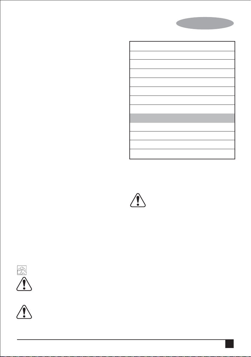
Using an Extension Cable
If it is necessary to use an extension cable, please used an
approvedextension cable that fits the tool’s power input
specifications (please refer to the technical data). The
minimum crosssectional area of the conducting wire is 1.5
sq. mm. Cables should be untangled before reeling up.
Please refer to the following table.
Cable cross-sectional area (mm2) Cable rated current (Ampere)
0.75 6
1.00 10
1.50 15
2.50 20
4.00 25
Cable length (m)
7.5 15 25 30 45 60
Voltage Amperes Cable rated current (Ampere)
115 0 - 2.0 6 6 6 6 6 10
2.1 - 3.4 6 6 6 6 15 15
3.5 - 5.0 6 6 10 15 20 20
5.1 - 7.0 10 10 15 20 20 25
7.1 - 12.0 15 15 20 25 25 -
12.1 - 20.0 20 20 25 - - -
230 0 - 2.0 6 6 6 6 6 6
2.1 - 3.4 6 6 6 6 6 6
3.5 - 5.0 6 6 6 6 10 15
5.1 - 7.0 10 10 10 10 15 15
7.1 - 12.0 15 15 15 15 20 20
12.1 - 20.0 20 20 20 20 25 -
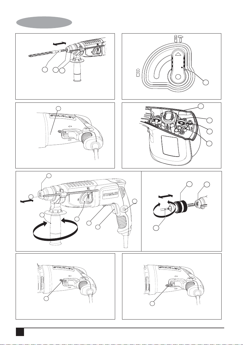
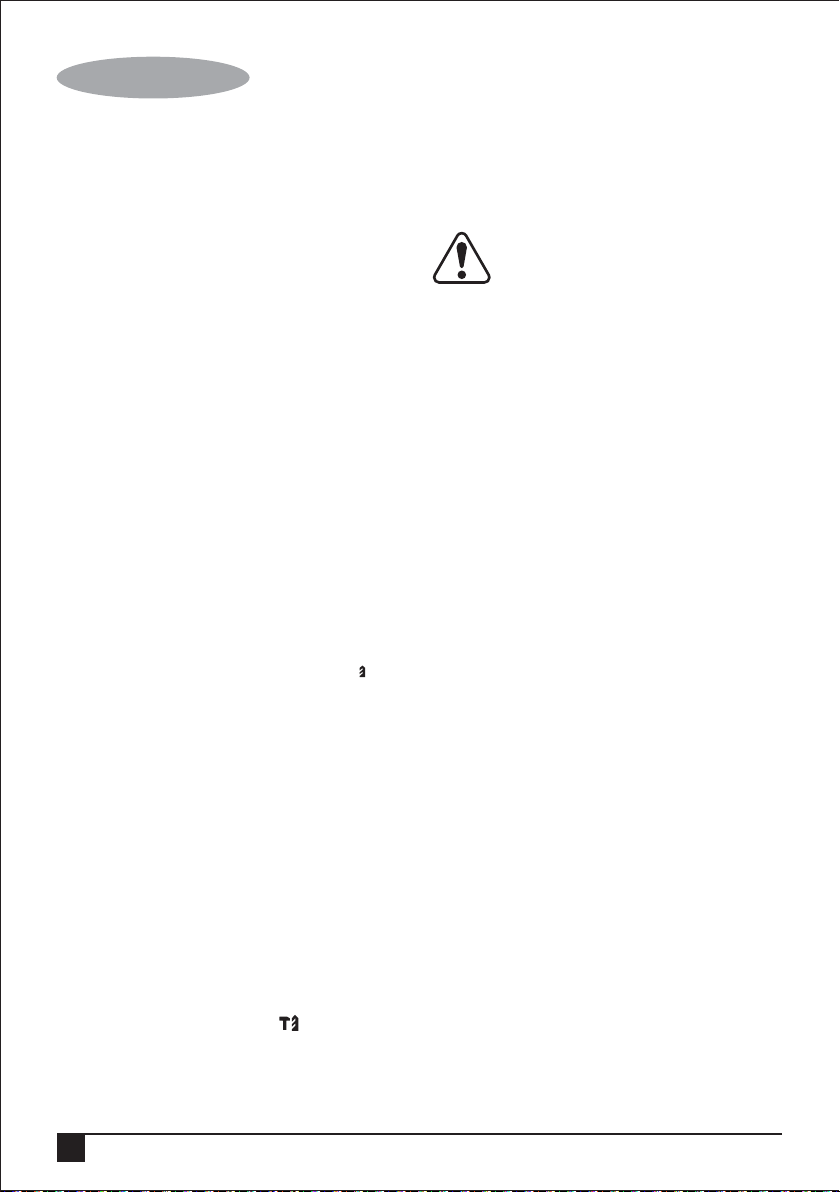
Features (Fig. E)
This tool includes some or all of the following features.
1. Variable speed switch
2. Lock-on button
3. Mode selector
4. Tool clamp
5. Side handle
6. Depth stop
7. Forward/Reverse lever
Assembly
Warning! Before assembly, make sure that the tool is
switched off and unplugged.
Attaching the Side Handle (fig. E)
Warning! When drilling holes in concrete or bricks, please
use the side handle for your safety.
• Turn the grip counterclockwise until you can slide the
side handle onto the front of the tool.
• Rotate the side handle into the desired position.
• Tighten the side handle by turning the grip clockwise.
Warning! When using the tool, remember to install the side
handles properly.
5
Page 6
ENGLISH
(Original instructions)
Fitting an accessory (fig.A)
• Clean and grease the shank (15) of the accessory.
• Insert the accessory bar into the tool clamp(4).
• Push the accessory down and turn it slightly until it fits
into the slots.
• Pull on the accessory to check if it is properly locked.
The hammering and drilling function requires the
accessory to be able to move axially several centimetres
when locked in the tool clamp.
• To remove the accessory, pull back the sleeve (8) and
pull out the accessory from the tool clamp.
Use
Warning! Please operate tool with normal load. Do not
overload.
Warning! Before drilling into walls, floors or ceilings, check
for the location of wiring and pipes.
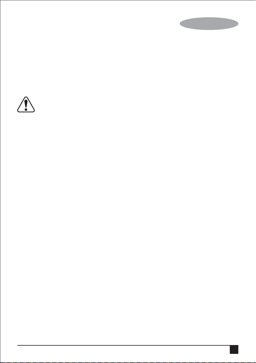
Selecting the Operating Mode (fig. B)
The tool can be used in two operating modes. Based on
actual work requirements, the drilling mode selector (3) can
be rotated to the required position.
Hole drilling / Screw driver (Fig. B,F,G,H)
• For drilling in steel, wood and plastics or tighten and loose
screw, set the operating mode selector (3) to the ( )
position. At the same time, it is necessary to use a
suitable drill chuck (13) (optional accessory) to clamp the
attachment rod.
• Insert the drill chuck (13) into the tool chuck (4) according
to the instructions for installing attachments. Turn the
drill chuck to loosen the clamps at the front-end of the
drillclamp, and insert the accessory bar (14) into the
clamps and turn the chuck in the opposite direction. You
may also use the drill chuck key to tighten the clamp.
• For drilling in steel, wood and plastics, set the forward/
reverse lever(7) to the forward position(Fig G). When use
for screw driver function, tighten screws set the forward/
reverse lever (7) to the forward position(Fig G) and loose
screws set the forward/reverse lever (7) to the reverse
position(Fig H).
Hammer drilling (Fig. B)
• For hammer drilling in masonry and concrete, set the
operating mode selector (3) to the position.
• The drill bit has to be placed accurately onto the drill
hole position. After that, pull the switch for optimal
effects. Make sure the tool is in the correct position to
prevent the drill from deviating from the hole.
6
• When the drill hole is clogged with debris or fine powder,
please don't exert any more pressure. Tool should be put
in free-running state before removing part of the drill bit
from the hole. If repeated a few times, the blockage in
the hole would be cleared, and normal drilling can
resume.
Warning! When the drill bit hits cement or the
steel rebar in the cement, the tool may recoil
dangerously. Please hold the tool tightly in a
prevent it from recoiling dangerously.
Overload coupling device
If the drill bit his caught or hooked, the driving force
transmitted to the drill shaft will be cut off. This would
generate a strong recoil, so it would be necessary to hold the
tool tightly with both hands to remain in a stable position.
Setting the drilling depth (Fig. E)
The depth stop is a convenient feature to ensure uniformity
in drilling depth. Loosen the side handle to adjust the depth
gauge according to the required depth. After that, tighten the
side handle.
• Slacken the side handle (5) by turning the grip
• Set the depth stop (6) to the required position. The
• Tighten the side handle by turning the grip clockwise.
Switching on and off
Warning! Before plugging in to the power source, make sure
the switch can be flipped freely, and can return to its original
position once released.
• To switch the tool on, press the variable speed switch
• As a general rule, use low speeds for large diameter drill
• For continuous operation, press the lock-on button (2)
• To switch the tool off, release the variable speed switch.
balanced and stable position at all times to
counterclockwise.
maximum drilling depth is equal to the distance between
the tip of the drill bit and the front end of the depth stop.
(1). The tool speed depends on how far you press the
switch.
bits and high speeds for smaller diameter drill bits.
and elease the variable speed switch.
To switch the tool off when in continuous operation, press
the variable speed switch once more and release it.
Accessories
The performance of your tool depends on the accessory
used. STANLEY accessories are engineered to high quality
standards and designed to enhance the performance of your
tool. By using these accessories you will get the very best
from your tool.
-
-
Page 7
(Original instructions)
ENGLISH
Maintenance
Your STANLEY corded/cordless appliance/tool has been
designed to operate over a long period of time with a
minimum of maintenance. To ensure satisfactory operations,
the tool must be maintained and cleaned regularly
Warning! Before performing any maintenance on corded/
cordless power tools:
• Switch off and unplug the appliance/tool.
• Or switch off and remove the battery from the appliance/
tool if the appliance/tool has a separate battery pack.
• Or run the battery down completely if it is integral and
then switch off.
• Unplug the charger before cleaning it. Your charger does
not require any maintenance apart from regular cleaning.
• Regularly clean the ventilation slots in your
appliance/tool/ charger using a soft brush or dry cloth.
• Regularly clean the motor housing using a damp cloth.
Do not use any abrasive or solvent-based cleaner.
• Regularly open the chuck and tap it to remove any dust
rom the interior (when fitted).
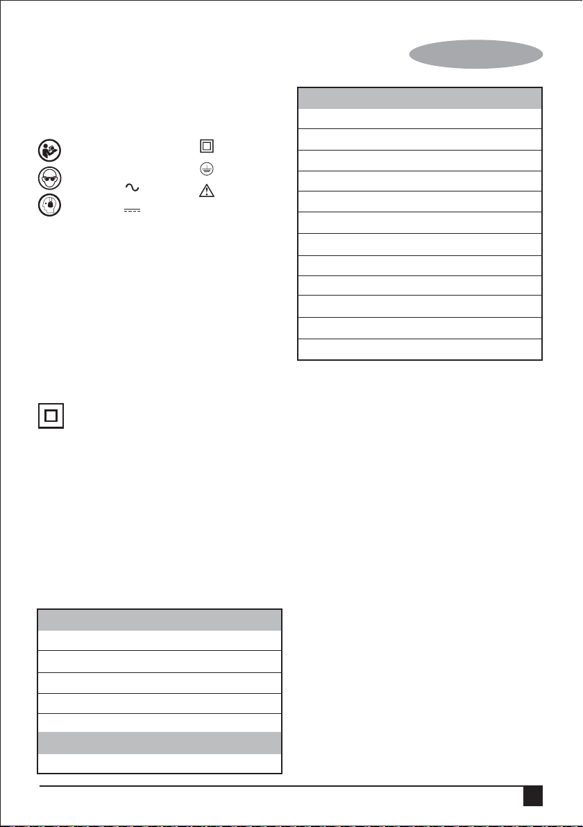
Replace the carbon brush (Fig. D)
• Regularly replace and inspect the carbon brush.
Oncecompletely worn out by continuous wear and
tear, it will have to be replaced. Must keep carbon
brush clean and sliding freely within the brush holder.
Both carbon brushes have to be replaced at the
same time.
• Remove the fixed screws (9) on the carbon brush to
remove the carbon brush (10) and brush holder.
• Remove the coil spring supporting the carbon brush
(11) in the brush holder, and insert a new carbon
brush that meets the specifications.
• Set up the brush holder again and return the
supporting coil spring to its original position.
Cleaning
Warning! Blow dirt and dust out of the main
housing with dry air as often as dirt is seen
collecting in and around the air vents. Wear
approved eye protection and approved dust
mask when performing this procedure.
Warning! Never use solvents or other harsh
chemicals for cleaning the non-metallic parts of
the tool. These chemicals may weaken the
material of the parts. Use only mild soap and damp cloth
to clean the tool. Never let any liquid get inside the tool;
never immerse any part of the tool into liquid.
Technical data
Rotary hammer STHR202
Power input W 620
Voltage V 220-240
Frequency Hz 50/60
No-load speed /min 0-1250
Impact rate BPM 0-3900
Impact energy J 1.34
Modes 2
Max drilling capacity
Concrete mm 20
Steel mm 13
Wood mm 25
Weight kg 2.6
The vibration emission level given in this information
sheet has been measured in accordance with a
standardised test given in EN 60745 and may be used to
compare one tool with another. It may be used for a
preliminary assessment of exposure.
Warning: The declared vibration emission
level represents the main applications of the
tool. However if the tool is used for different
poorly maintained, the vibration emission may differ. This
may significantly increase the .5exposure level over the
total working period. An estimation of the level of
exposure to vibration should also take into account the
times when the tool is switched off or when it is running
but not actually doing the job. his may significantly
reduce the exposure level over the total working period.
Identify additional safety measures to rotect the operator
from the effects of vibration such as: aintain the tool and
the accessories, keep the hands arm, organisation of
work patterns.
LpA (sound pressure) 88.0 dB(A)
KpA (sound pressure uncertainty) dB(A) 3
LWA (sound power) 99.0 dB(A)
KWA (sound power uncertainty) dB(A) 3
Vibration emission value ah
ah, HD (Hammer Drilling into concrete) = 13.7 m/s²
Uncertainty K = m/s² 1,5
applications, with different accessories or
7
Page 8
ENGLISH
(Original instructions)
Protecting the environment
Separate collection. This product must not be
disposed of with normal household waste.
Should you find one day that your STANLEY product needs
replacement, or if it is of no further use to you, do not
dispose of it with household waste. Make this product
available for separate collection.
Separate collection of used products and packaging
allows materials to be recycled and used again.
Re-use of recycled materials helps prevent
environmental pollution and reduces the demand for raw
materials.
Local regulations may provide for separate collection of
electrical products from the household, at municipal waste
sites or by the retailer when you purchase a new product.
STANLEY provides a facility for the collection and recycling
of STANLEY products once they have reached the end of
their working life. To take advantage of this service please
return your product to any authorised repair agent who will
collect them on our behalf.
You can check the location of your nearest authorised repair
agent by contacting your local STANLEY office at the
address indicated in this manual. Alternatively, a list of
authorised STANLEY repair agents and full details of our
after-sales service and contacts are available on the Internet
at: www.2helpU.com
Two years full warranty
If your STANLEY product becomes defective due to faulty
materials or workmanship within 24 months from the date of
purchase, STANLEY guarantees to replace all defective
parts free of charge or – at our discretion – replace the unit
free of charge provided that:
• The product has not been misused and has been used in
accordance with the instruction manual.
• The product has been subject to fair wear and tear;
• Repairs have not been attempted by unauthorised
• Proof of purchase is produced.
• The STANLEY product is returned complete with all
original components
If you wish to make a claim, contact your seller or check the
location of your nearest authorised STANLEY repair agent in
the STANLEY catalogue or contact your local STANLEY
office at the address indicated in this manual. A list of
authorised STANLEY repair agents and full details of our
after sales service is available on the internet
at:www.stanleytools.com
EC declaration of conformity
MACHINERY DIRECTIVE
STHR202K - Rotary hammer
STANLEY declares that these products described under
"technical data" are in compliance with 2006/42/EC, EN
60745-1:2009 + A11:2010, EN 60745-2-4:2009+A11:2011
These products also comply with Directive 2004/108/EC
(until 19/04/2016), 2014/30/EU (from 20/04/2016) and
2011/65/EU. For more information, please contact STANLEY
at the following address or refer to the back of the manual.
The undersigned is responsible for compilation of the
technical file and makes this declaration on behalf of
R.Laverick
Engineering Manager
STANLEY , Europe, Egide Walschaertsstraat14-18,
2800 Mechelen, Belgium
08.2015
8
Page 9

(Перевод с оригинала инструкции)
РУССКИЙ
Использование по назначению
Ваш перфоратор STANLEY SDS plus STHR202
предназначен для сверления отверстий в бетоне,
кирпиче, древесине и стали. Данный инструмент
предназначен для профессионального и
полупрофессионального использования.
Правила техники безопасности
Общие предупреждения по технике безопасности
электроинструментов
Внимание! Ознакомьтесь со всеми
правилами безопасности и инструкциями.
Несоблюдение предупреждений и инструкций,
указанных ниже, может привести к поражению
электрическим током, пожару и/или серьезной травме.
Сохраните все предупреждения и инструкции для
будущего использования.
Термин "электроинструмент" во всех предупреждениях,
указанных ниже, относится к вашему сетевому (с
кабелем) электроинструменту или аккумуляторному
электроинструменту (без кабеля питания).
1. Безопасность рабочего места
а. Содержите рабочее место в чистоте и хорошо
освещенным. Беспорядок на рабочем месте или
отсутствие освещения рабочего места может
привести к аварии.
b. Не работайте с электроинструментом в месте
хранения взрывоопасных материалов,
например, в присутствии огнеопасных
жидкостей, газов или пыли. Электрические
инструменты создают искры, которые могут
воспламенить пыль или пары.
с. Дети и посторонние лица должны находиться как
можно дальше во время работы с
электроинструментом. Вы можете отвлечься и
потерять контроль.
2. Электробезопасность
а. Вилка электроинструмента должна
соответствовать розетке. Никогда не
модифицируйте вилку каким-либо образом. Не
используйте никакие вилки-переходники с
заземленными (замкнутыми на землю)
электроинструментами. Вилки и розетки, которые
не подвергались никаким изменениям снижают риск
поражения электрическим током.
b. Избегайте контакта тела с заземленными
поверхностями, такими как трубы, радиаторы,
плиты и холодильники. Существует повышенный
риск поражения электрическим током, если ваше
тело заземлено.
с. Избегайте любого воздействия дождя или влаги
на электроинструменты. Вода, попавшая в
электроинструмент, увеличивает риск поражения
электрическим током.
d. Аккуратно обращайтесь со шнуром питания.
Никогда не используйте шнур питания для
переноски, перемещения или извлечения вилки
из розетки. Держите шнур вдали от источников
тепла, масла, острых краев или движущихся частей.
Поврежденные или запутанные шнуры увеличивают
риск поражения электрическим током.
е. При работе с электроинструментом на улице,
используйте удлинитель, подходящий для
наружного использования. Использование кабеля,
пригодного для использования на открытом воздухе,
снижает риск поражения электрическим током.
f. При необходимости работы с
электроинструментом во влажной среде,
используйте устройство защитного отключения
(УЗО). Использование УЗО снижает риск поражения
электрическим током. Примечание: Термин
“устройство защитного отключения (УЗО)” может
быть заменен на "аварийный прерыватель
заземления" или "автоматический выключатель тока
утечки".
3. Личная безопасность
a. Будьте внимательны, смотрите, что вы делаете,
используйте здравый смысл при работе с
электроинструментом. Не используйте
электроинструмент, если вы устали или находитесь
под влиянием наркотиков, алкоголя или лекарств.
Малейшая неосторожность при работе с
электроинструментом может привести к серьезным
травмам.
b. Используйте средства индивидуальной защиты.
Всегда надевайте защитные очки. Другое
защитное оборудование, включая респиратор,
ботинки на нескользящей подошве, защитный
шлем или средства защиты органов слуха,
используемые в надлежащих условиях, уменьшат
риск получения травмы.
с. Для предотвращения случайного запуска,
убедитесь, что переключатель находится в
выключенном положении перед подключением к
источнику питания и/или аккумуляторной
батарее, поднятия или переноски инструмента. Не
переносите электроинструмент с пальцем на
выключателе и не включайте питание на инструмент
с включенным выключателем, что может привести к
несчастному случаю.
d. Перед включением электроинструмента снимайте
регулировочный или гаечный ключ. Гаечный или
регулировочный ключ, оставленный на
вращающейся части электроинструмента, может
привести к травме.
9
Page 10

РУССКИЙ
(Перевод с оригинала инструкции)
е. Не тянитесь. Сохраняйте правильную стойку и
баланс все время. Это позволяет лучше
контролировать инструмент в неожиданных
ситуациях.
f. Одевайтесь правильно. Не надевайте свободную
одежду или украшения. Держите волосы, одежду
и перчатки вдали от движущихся частей.
Свободная одежда, украшения или длинные
волосы могут попасть в движущиеся части.
g. Если имеются устройства для подключения
пылесборника или вытяжки, убедитесь в том, что
они подсоединены и используются правильно.
Использование пылесборника снижает вероятность
возникновения рисков, связанных с пылью.
4. Использование и уход за электроинструментом
a. Не перегружайте электроинструмент.
Используйте подходящий электрический
инструмент для соответствующего применения.
Правильно подобранный электроинструмент
позволит выполнить работу лучше и безопаснее при
скорости, для которой он был разработан.
b. Не используйте электроинструмент, если
переключатель не может его включить и
выключить. Любой электроинструмент, который
нельзя контролировать с помощью переключателя,
опасен и должен быть отремонтирован.
c. Отключите кабель питания от источника питания
и/или аккумуляторный блок от электрического
инструмента перед выполнением любых
регулировок, замены принадлежностей или при
хранении электроинструмента. Такие
профилактические меры безопасности уменьшают
риск непреднамеренного запуска электрического
инструмента.
d. Храните неиспользуемые электроинструменты в
недоступном для детей месте и не позволяйте
лицам, не знакомым с электроинструментом или
данными инструкциями, работать с
электроинструментом. Электроинструменты опасны
в руках неопытных пользователей.
е. Поддержание электроинструмента. Проверяйте
разрегулированность или cоединение
подвижных частей, поломки частей и любые
другие условия, которые могут повлиять на
работу электроинструмента. При наличии
повреждения, отремонтируйте
электроинструмент перед использованием.
Многие несчастные случаи являются следствием
плохого ухода за электроинструментом.
f. Держите режущий инструмент острым и чистым.
Хорошо ухоженный режущий инструмент с острыми
режущими кромками легче контролировать.
g. Используйте электроинструмент, аксессуары и
сверла в соответствии с данными инструкциями
и в порядке, предназначенном для конкретного
типа электрического инструмента, принимая во
внимание условия и характер выполняемой
работы. Использование электрического инструмента
для операций, отличающихся от тех, для которых он
предназначен может привести к опасной ситуации.
5. Обслуживание
а. Обеспечьте, чтобы обслуживание и ремонт
вашего электроинструмента проводился в
авторизованном сервисном центре по ремонту с
использованием только оригинальных запасных
частей. Это станет гарантией безопасности
электроинструмента.
* Примечание: Напряжение сети: при подключении к
сети, необходимо проверить, если напряжение сети
совпадает с электроинструментом. Если напряжение в
сети превышает напряжение, указанное на инструменте,
пользователь может получить травмы и увечья в
результате несчастного случая, а инструмент может
быть поврежден. Если же напряжение сети ниже, чем
напряжение, требуемое для инструмента, двигатель
может быть поврежден. Таким образом, если
невозможно, проверить напряжение, крайне важно не
подключать инструмент к источнику питания.
Предупреждения по безопасности для
молота
• Надевайте защитные наушники. Воздействие шума
может привести к потере слуха.
• Используйте дополнительные рукоятки, если они
входят в комплект поставки инструмента. Потеря
контроля может привести к травме.
• Держите инструмент за изолированные
поверхности во время работы, при которой
режущий инструмент может задеть скрытую
проводку или собственный кабель. При контакте
режущего аксессуара с «работающим» проводом или
открытыми металлическими частями
электроинструмента оператора может ударить
электрическим током.
• Никогда не используйте долото в ротационном
режиме. Аксессуар войдет в материал и приведет к
вращению дрели.
• Используйте тиски или другое подходящее
приспособление для обеспечения и поддержания
обрабатываемого изделия на устойчивой
платформе. Проведение работы по направлению
руки или против вашего тела, лишает устойчивости и
может привести к потере контроля.
• Перед сверлением стен, полов и потолков,
проверьте местоположение электропроводки и труб.
• Не прикасайтесь к кончику сверла сразу после
окончания сверления во избежании ожогов.
10
Page 11

(Перевод с оригинала инструкции)
РУССКИЙ
• Назначение инструмента описывается в данном
руководстве. Использование любых аксессуаров или
приспособлений или выполнение любых операций с
помощью этого инструмента, не рекомендованных в
данном руководстве, может представлять опасность
получения травм и/или повреждения имущества.
Безопасность посторонних лиц
• Этот инструмент не предназначен для
использования лицами (включая детей) с
ограниченными физическими, чувствительными или
умственными способностями или с недостатком
опыта или знаний, если они не были под контролем и
руководством лица, контролирующего использование
инструмента или ответственным за их безопасность.
• Дети должны быть под присмотром взрослых, чтобы
не допустить никаких игр с инструментом.
Другие риски
Дополнительные остаточные риски могут возникнуть при
использовании инструмента, который не может быть
включен в описанные здесь правила техники
безопасности. Эти риски могут возникнуть при
неправильном или продолжительном использовании
изделия и т.п. Несмотря на соблюдение
соответствующих правил техники безопасности и
использование предохранительных устройств,
некоторых остаточных рисков невозможно избежать.
Они включают в себя:
• Травмы в результате касания
вращающихся/движущихся частей.
• Риск получения травмы во время смены деталей
инструмента, ножей или насадок.
• Травмы, вызванные продолжительным
использованием инструмента. При использовании
инструмента в течение продолжительного периода
времени делайте регулярные перерывы в работе.
• Плохой слух
• Ущерб здоровью в результате вдыхания пыли при
использовании инструмента (пример: работа с
деревом, в особенности, с древесиной дуба, бука и
древесноволокнистой плитой средней плотности)
Этикетки на инструменте
Наравне с кодом даты на инструменте могут
находиться следующие знаки:
Читайте
инструкции по
эксплуатации
Используйте
средства
защиты глаз
Используйте
средства
защиты
органов слуха
В ........ Вольт
A ........ Ампер
Гц ....... Герц
Вт ........ Ватт
мин...... минуты
Перемен-
.....
ный ток
Постоян-
.....
ный ток
Скорость
n
.......
0
без нагрузки
Конструкция
......
класса II
Терминал
....
заземления
Символ
предупреж-
....
дения об
опасности
обороты или
...мин..
возвратнопоступательное движение
в минуту
Положение даты штрих-кода
Дата кода, который также включает год изготовления,
печатается на корпусе.
Пример:
2014 XX JN
Год изготовления
Электрическая безопасность
Ваш инструмент защищен двойной изоляцией,
поэтому заземляющий провод не требуется.
Всегда проверяйте, чтобы напряжение сети
соответствовало напряжению, указанному на заводской
табличке.
• Если оригинальный шнур питания поврежден, он
должен быть заменен производителем или
уполномоченным сервисного центра STANLEY для
того, чтобы избежать опасности.
Использование удлинителя
Если необходимо использовать удлинитель,
пожалуйста, используйте утвержденный удлинительный
кабель, который соответствует спецификации входного
питания инструмента (пожалуйста, обратитесь к
техническим данным). Минимальная площадь
поперечного сечения проводящей проволоки составляет
1,5 кв. мм. Кабели следует предварительно распутать.
11
Page 12

РУССКИЙ
(Перевод с оригинала инструкции)
Пожалуйста обратитесь к слудующей таблице:
Площадь поперечного Номинальный ток допустимый
сечения кабеля (мм2) для кабеля (ампер)
0.75 6
1.00 10
1.50 15
2.50 20
4.00 25
Длина кабеля (м)
7.5 15 25 30 45 60
Напряжение Ампер
для кабеля (ампер)
115 0 - 2.0 6 6 6 6 6 10
2.1 - 3.4 6 6 6 6 15 15
3.5 - 5.0 6 6 10 15 20 20
5.1 - 7.0 10 10 15 20 20 25
7.1 - 12.0 15 15 20 25 25 -
12.1 - 20.0 20 20 25 - - -
230 0 - 2.0 6 6 6 6 6 6
2.1 - 3.4 6 6 6 6 6 6
3.5 - 5.0 6 6 6 6 10 15
5.1 - 7.0 10 10 10 10 15 15
7.1 - 12.0 15 15 15 15 20 20
12.1 - 20.0 20 20 20 20 25 -
Номинальный ток допустимый
Характеристики
Этот инструмент включает в себя некоторые или все из
следующих характеристик.
1. Переключатель плавного хода/скоростей
2. Кнопка блокировки
3. Селектор режимов
4. Зажим инструмента
5. Боковая рукоятка
6. Ограничитель глубины
7. Переключатель направления вращения
12
Сборка
Предостережение! Перед сборкой убедитесь, что
инструмент выключен и отключен от источника питания.
Установка боковой рукоятки (рис. Е)
Предостережение! При сверлении отверстий в бетоне
или кирпиче, пожалуйста, используйте боковую рукоятку
для вашей безопасности.
• Поверните рукоятку против часовой стрелки до тех
пор, пока можно сдвинуть боковую рукоятку к
передней части инструмента.
• Поверните боковую рукоятку в нужное положение.
• Затяните боковую рукоятку, повернув рукоятку по
часовой стрелке.
Предостережение! При использовании инструмента, не
забудьте установить боковые ручки правильно.
Установка аксессуара (рис. A)
• Очистите и смажьте хвостовик (15) аксессуара.
• Вставьте планку аксессуара в зажим инструмента (4).
• Нажмите аксессуар вниз и немного поверните его
пока он не войдет в пазы.
• Потяните аксессуар, чтобы проверить, правильно ли
он закрывается. Ударное бурение и сверление
требует, чтобы аксессуар имел возможность
перемещаться в осевом направлении на несколько
сантиметров, когда он блокируется в зажиме
инструмента.
• Чтобы удалить аксессуар, потяните рукав обратно (8)
и вытяните аксессуар из зажима инструмента.
Использование
Внимание! Пожалуйста, работайте с инструментом с
нормальной нагрузкой. Не перегружайте его.
Предостережение! Перед сверлением стен, полов и
потолков, проверьте наличие электропроводки и труб.
Выбор режима работы (рис. B)
Этот инструмент может быть использован в двух
режимах работы. Исходя из фактических потребностей в
работе, селектор режима бурения/сверления (3) может
быть повернут в требуемое положение.
Page 13

(Перевод с оригинала инструкции)
РУССКИЙ
Сверление отверстий / Заворачивание (Рис. B, F, G, H)
• Для сверления в металле, древесине и пластиках, а
также для заворачивания саморезов установите
переключатель режимов работы (3) в положение .
В то же время, необходимо использовать
соответствующий патрон (13) (дополнительная
принадлежность), чтобы зафиксировать хвостовик
насадки.
• Вставьте в держатель (4) патрон (13) в соответствии
с инструкциями по установке насадок. Поверните
патрон, чтобы ослабить зажим в передней части
держателя насадок, вставьте в зажим хвостовик
насадки (14) и поверните патрон в обратном
направлении. Вы также можете использовать
патрон, чтобы затянуть зажим.
• Для сверления в металле, древесине и пластиках
установите переключатель направления вращения
(7) в переднее положение (Рис. G). Для
использования инструмента для заворачивания
саморезов устанавливайте переключатель
направления вращения (7) в переднее положение
(Рис. G), для выкручивания саморезов
устанавливайте переключатель направления
вращения (7) в положение реверса (Рис. Н).
Сверление с ударом (рис. B)
• Для сверления с ударом в кирпичной кладке и
бетоне, установите переключатель режимов работы
(3) в нужное положение.
• Сверло должно быть помещено точно в отверстие
дрели. После этого потяните переключатель для
достижения оптимального эффекта. Убедитесь, что
инструмент находится в правильном положении,
чтобы предотвратить сверло от отклонения от
отверстия.
• Когда высверливаемое отверстие забивается
мусором или мелкой пылью, пожалуйста, не
оказывайте никакого надавливания. Инструмент
должен быть переведен с состояние свободной
работы перед удалением части сверла из отверстия.
Если повторить эту процедуру несколько раз, вы
освободите отверстие от засорения, после чего
можно возобновить обычное сверление.
Предостережение! Когда сверло попадает
в цемент или стальную арматуру в цементе,
с инструментом может произойти опасный
эффект отдачи. Пожалуйста, держите
инструмент плотно в сбалансированном и
стабильном положении в течение всего времени
работы, чтобы предотвратить эффект отдачи.
Предохранительная муфта
Если сверло зажимается или искривляется, движущая
сила, передаваемая на бурильный вал, будет
отключена. Создается огромная сила, таким образом,
две руки должны плотно держать электроинструмент,
когда он находится в работе, и убедитесь, что оператор
находится в стабильном и неподвижном положении.
Установка глубины сверления (рис. E)
Ограничитель глубины является удобной функцией для
обеспечения однородности глубины сверления.
Ослабьте боковую рукоятку, чтобы отрегулировать
ограничитель глубины в зависимости от требуемой
глубины. После этого затяните боковую рукоятку.
• Ослабьте боковую рукоятку (5), повернув ручку
против часовой стрелки.
• Установите ограничитель глубины сверления (6) в
требуемое положение. Максимальная глубина
сверления равна расстоянию между кончиком сверла
и передней частью ограничителя глубины.
• Затяните боковую рукоятку, повернув рукоятку по
часовой стрелке.
Включение и выключение
Предостережение! Перед подключением к источнику
питания, убедитесь, что переключатель свободно
передвигается и может вернуться в исходное положение
после отпускания.
• Чтобы включить инструмент, нажмите
переключатель плавного хода (1). Скорость
инструмента зависит от того, насколько сильно вы
нажмете переключатель.
• Как правило, используют низкие скорости для сверл
большого диаметра и высокие скорости для сверл
малого диаметра.
• Для непрерывной работы нажмите фиксатор
клавиши (2) и отпустите переключатель плавного
хода.
• Чтобы включить инструмент, отпустите кнопку
включателя. Чтобы выключить инструмент, когда он
находится в непрерывном режиме работе, нажмите
переключатель плавного хода еще раз и отпустите
его.
Аксессуары
Производительность вашего инструмента зависит от
используемых аксессуаров. Аксессуары STANLEY
разработаны согласно высоким стандартам качества, и
они способны увеличить производительность вашего
электроинструмента. Используя эти принадлежности, вы
сможете наиболее эффективно использовать ваш
инструмент.
13
Page 14

РУССКИЙ
(Перевод с оригинала инструкции)
Обслуживание�
Ваши проводные/беспроводные
устройства/инструменты STANLEY были разработаны
для работы в течение длительного периода времени
при минимальном техническом обслуживании. Для
обеспечения удовлетворительной работы, инструмент
должен правильно храниться и подвергаться регулярной
чистке.
Предостережение! Перед выполнением любых работ
по обслуживанию проводных/беспроводных
электроинструментов:
• Выключите и отсоедините прибор/инструмент.
• Или отключите его и удалите батарею из
устройства/инструмента, если прибор/инструмент
имеет отдельный аккумулятор.
• Или запустите батарею полностью, если она
встроена, а затем выключите.
• Отключите зарядное устройство перед чисткой.
Ваше зарядное устройство не требует никакого
обслуживания, кроме регулярной чистки.
• Регулярно очищайте вентиляционные прорези
инструмента/прибора/зарядного устройства мягкой
щеткой или сухой тканью.
• Регулярно очищайте корпус двигателя влажной
тканью. Не используйте абразивные материалы или
материалы на основе растворителя для чистки.
• Регулярно открывайте и проворачивайте патрон,
чтобы удалить пыль изнутри (при засорении).
Замена угольных щеток (рис. D)
Смазка
• Регулярно заменяйте и проверяйте угольные щетки.
Заменяйте их своевременно по мере естественного
износа. Содержите угольные щетки в чистоте и
убедитесь, чтобы они свободно скользили в
процессе чистки. Обе щетки должны быть заменены
одновременно.
• Удалите фиксированные винты (9) на угольной
щетке для снятия угольной щетки (10) и держателя
щетки.
14
• Удалите пружину, поддерживающую угольные щетки
(11) в держатель щетки, и вставьте новую угольную
щетку, которая соответствует требованиям.
• Установите держатель щетки снова и верните
опорную спиральную пружину в исходное положение.
Чистка
Предостережение! Выдувайте грязь и пыль
из основного корпуса при помощи сухого
воздуха каждый раз, когда вы видите
скопление грязи и пыли внутри и вокруг вентиляционных
отверстий. Надевайте средство защиты глаз и
респиратор, утвержденные для использования при
выполнении этой процедуры.
Внимание! Никогда не используйте
растворители или другие агрессивные
химикаты для очистки неметаллических
деталей инструмента. Эти химические вещества могут
ослабить свойства материала, из которого они
изготовлены. Используйте только мягкое мыло и
влажную ткань, чтобы очистить инструмент. Никогда не
допускайте попадания жидкости внутрь инструмента и не
погружайте никакую часть инструмента в жидкость.
Технические данные
Бурильный молоток для STHR202
вращательного бурения
Входная мощность W 620
Напряжение V 220-240
Частота Hz 50/60
Скорость без нагрузки /мин 0-1250
Частота ударов bpm 0-3900
Энергия удара J 1,34
Режимы 2
Макс диаметр сверления
Бетон мм 20
Сталь мм 13
Дерево мм 25
Масса кг 2,6
Page 15
(Перевод с оригинала инструкции)
Защита окружающей среды
Раздельный сбор и утилизация. Этот продукт
не следует утилизировать вместе с бытовым
мусором.
Если вы поймете, что ваш продукт Stanley нуждается в
замене, или если он не имеет никакого дальнейшего
применения для вас, не выбрасывайте его вместе с
бытовыми отходами. Предоставьте этот продукт для
раздельного сбора/утилизации.
Раздельный сбор продуктов и упаковок
позволяет осуществить их переработку и
использовать их повторно. Повторное
использование переработанных материалов помогает
защищать окружающую среду от загрязнения и снижает
расход сырьевых материалов.
Местное законодательство может обеспечить сбор
старых электроинструментов отдельно от бытового
мусора на муниципальных свалках отходов или в
торговом предприятии при покупке нового изделия.
Stanley обеспечивает возможность для сбора и
утилизации продуктов Stanley, как только они достигли
конца своего срока службы. Для того чтобы
воспользоваться этой услугой, вы можете сдать ваше
изделие в любой авторизованный сервисный центр,
который собирает их по нашему поручению.
РУССКИЙ
Вы можете узнать место нахождения вашего
ближайшего авторизованного сервисного центра,
обратившись в местное отделение Stanley по адресу,
указанному в данном руководстве. Кроме того, список
авторизованных ремонтных агентов Stanley и полную
информацию о нашем послепродажном обслуживании и
контактах вы можете найти в Интернете:
www.2helpU.com
15
Page 16

РУССКИЙ
(Перевод с оригинала инструкции)
Гарантийные условия
Уважаемый покупатель!
1. Поздравляем Вас с покупкой высококачественного
изделия STANLEY и выражаем признательность за Ваш
выбор.
2. При покупке изделия требуйте проверки его комплектности
и исправности в Вашем присутствии, инструкцию по
эксплуатации и заполненный гарантийный талон на
русском языке.
В гарантийном талоне должны быть внесены: модель,
дата продажи, серийный номер, дата производства
инструмента; название, печать и подпись торговой
организации. При отсутствии у Вас правильно заполненного гарантийного талона, а также несоответствия
указанных в нем данных мы будем вынуждены откло- нить
Ваши претензии по качеству данного изделия.
3. Во избежание недоразумений убедительно просим Вас
перед началом работы с изделием внимательно
ознакомиться с инструкцией по его эксплуатации.
Правовой основой настоящих гарантийных условий
является действующее Законодательство. Гарантийный
срок на данное изделие составляет 24 месяца и
исчисляется со дня продажи. В случае устранения
недостатков изделия, гарантийный срок продлевается на
период его нахождения в ремонте. Срок службы изделия
составляет 5 лет со дня продажи.
4. В случае возникновения каких-либо проблем в про- цессе
эксплуатации изделия рекомендуем Вам обра- щаться
только в уполномоченные сервисные центры STANLEY,
адреса и телефоны которых Вы сможете найти в
гарантийном талоне, на сайте www.2helpU.com или узнать
в магазине. Наши сервисные станции - это не только
квалифицированный ремонт, но и широкий ассортимент
запчастей и принадлежностей.
5. Производитель рекомендует проводить периодическую
проверку и техническое обслуживание изделия в
уполномоченных сервисных центрах.
Изготовитель
Блэк энд Деккер Холдингс ГмбХ
Германия, 65510, Идштайн,
ул. Блэк энд Деккер, 40
6. Наши гарантийные обязательства распространяются
только на неисправности, выявленные в течение гарантийного срока и вызванные дефектами производства и \
или материалов.
7. Гарантийные условия не распространяются на
неисправности изделия, возникшие в результате:
7.1. Несоблюдения пользователем предписаний инструкции по
эксплуатации изделия, применения изделия не по
назначению, неправильном хранении, использования
принадлежностей, расходных материалов и запчастей, не
предусмотренных производителем.
7.2. Механического повреждения (сколы, трещины и разрушения) внутренних и внешних деталей изделия,
основных и вспомогательных рукояток, сетевого электрического кабеля, вызванного внешним ударным или
любым иным воздействием
7.3 Попадания в вентиляционные отверстия и проникновение внутрь изделия посторонних предметов,
материалов или веществ, не являющихся отходами,
сопровождающими применение изделия по назначению,
такими как: стружка, опилки, песок, и пр.
7.4. Воздействий на изделие неблагоприятных атмосферных и
иных внешних факторов, таких как дождь, снег,
повышенная влажность, нагрев, агрессивные среды,
несоответствие параметров питающей электросети,
указанных на инструменте.
7.5. Стихийного бедствия. Повреждение или утрата изделия,
связанное с непредвиденными бедствиями, стихийными
явлениями, в том числе вследствие действия
непреодолимой силы (пожар, молния, потоп и другие
природные явления), а так же вследствие перепадов напряжения в электросети и другими причинами, которые
находятся вне контроля производителя.
8. Гарантийные условия не распространяются:
8.1. На инструменты, подвергавшиеся вскрытию, ремонту или
модификации вне уполномоченного сервисного центра.
8.2. На детали и узлы, имеющие следы естественного износа,
такие как:
приводные ремни и колеса, угольные щетки, смазка,
подшипники, зубчатое зацепление редукторов, резиновые уплотнения, сальники, направляющие ролики,
муфты, выключатели, бойки, толкатели, стволы, и т.п.
8.3. На сменные части: патроны, цанги, зажимные гайки и
фланцы, фильтры, аккумуляторные батареи, ножи,
шлифовальные подошвы, цепи, звездочки, пильные шины,
защитные кожухи, пилки, абразивы, пильные и
абразивные диски, фрезы, сверла, буры и т.п.
8.4. На неисправности, возникшие в результате перегрузки
инструмента (как механической, так и электрической),
повлекшей выход из строя одновременно двух и более
деталей и узлов, таких как: ротора и статора, обеих
обмоток статора, ведомой и ведущей шестерни редуктора или других узлов и деталей. К безусловным
признакам перегрузки изделия относятся, помимо прочих:
появление цветов побежалости, деформация или
оплавление деталей и узлов изделия, потемнение или
обугливание изоляции проводов электродвигателя под
воздействием высокой температуры.
16
Page 17

5'-F2
R(+1"D
S'+"1$D
51".
=/"'$D
518
KE(D
KE$D
=+@*-.
:'(.F7"D
6).F7"D
O%F7"D
?')17"D
>%, /"%#L+%,-.+1
O','$F
01
05
09
14
18
22
27
31
36
40
44
49
2014
02
06
10
15
19
23
28
32
37
41
45
50
03
07
11
16
20
24
29
33
38
42
46
51
04
08
12
17
21
25
30
34
39
43
47
52
05
09
13
18
22
26
31
35
40
44
48
14
27
O','$F
01
05
09
14
18
23
27
31
36
40
44
49
2015
02
06
10
15
19
24
28
32
37
41
45
50
03
07
11
16
20
25
29
33
38
42
46
51
04
08
12
17
21
26
30
34
39
43
47
52
09
13
18
22
27
31
35
40
44
48
53
14
36
49
01
05
09
13
17
22
26
31
35
39
44
48
2016
02
06
10
14
18
23
27
32
36
40
45
49
03
07
11
15
19
24
28
33
37
41
46
50
04
08
12
16
20
25
29
34
38
42
47
51
09
13
17
21
26
30
35
39
43
48
52
22
44
01
05
09
13
18
22
26
31
35
39
44
48
2017
02
06
10
14
19
23
27
32
36
40
45
49
03
07
11
15
20
24
28
33
37
41
46
50
04
08
12
16
21
25
29
34
38
42
47
51
05
09
13
17
22
26
30
35
39
43
48
52
31
44
(Перевод с оригинала инструкции)
РУССКИЙ
!" # $ % & ' ( # ' ) " * ) % +%,-.+* /% 0 ) - / $ * 1 . 1 2 # #
5%,'$#: STHR223, STHR263, STHR272, STHR323, STHR243, FME500, FME1250, FME1250KPPE., STHR202
5%,'$#: STHM5, STHM10.
:'".#3#)1. <: RU C-DE.=>49.B .03916
?'8-.+#.'$'( ,%: 12 91".1 2018 @.
A4,1(: 67B'-.+% - %@"1(#C'((%8 %.+'.-.+'((%-.DE " >#$D,#F
;1C'-.+1", 1,"'- 9'-.%(1G%&,'(#F: 115088, @%"%, 5%-)+1,
H1"#)%/%,I#/(#)%+-)1F *$#21, ,%9 4, )%"/*- 12, 31).#C'-)#8 1,"'-:
248018, ;1$*&-)1F %7$1-.D, @%"%, ;1$*@1, *$#21 ;1"$1 J#7)('G.1, ,%9
31, .'$'3%(: +7(4842) 22-02-81, 31)-: +7(499)372-00-89, e-mail:
gk.tr.ts@gmail.com .
KL@%.%+#.'$D: M$0) 0(, ?'))'" N%$,#(@- >97N
>'"91(#F, 65510, K,I.18(,
*$. M$0) 0(, ?'))'", 40
N
"1 ( '( # ' .
O'%7G%,#9% G"1(#.D + -*G%9 9'-.', +,1$# %. #-. %C(#)%+ /%+4I'((4G
.'9/'"1.*" # +%L,'8-.+#F -%$('C(4G $*C'8. !"# G"1('(## ('%7G%,#9%
#L7'@1.D "'L)%@% /'"'/1,1 .'9/'"1.*". N"1('(#' 7'L */1)%+)# ('
,%/*-)1'.-F
:
"% ) - $ *& 7 4 .
:"%) -$*&74 #L,'$#F -%-.1+$F'. 5 $'.. O' "')%9'(,*'.-F )
0)-/$*1.12## /% #-.'C'(## 5 $'. G"1('(#F - ,1.4 #L@%.%+$'(#F 7'L
/"',+1"#.'$D(%8 /"%+'")#.?1.1 #L@%.%+$'(#F ()%, ,1.4) *)1L1(1 (1
)%"/*-' #(-."*9'(.1.
;%, ,1.4, )%.%"48 .1)&' +)$EC1'. @%, #L@%.%+$'(#F, %.I.19/%+1(
(1 /%+'"G(%-.# )%"/*-1 #L,'$#F..
!"#9'":
2014 46 XX, @,' 2014 –@%, #L@%.%+$'(#F, 46-(','$F #L@%.%+$'(#F.
6/"','$#.D 9'-F2 #L@%.%+$'(#F /% *)1L1((%8 (','$' #L@%.%+$'(#F
9%&(% -%@$1-(% /"#+','((%8 (#&' .17$#2'.
:,'$1(% + ;#.1'.
!'"3%"1.%"4
6.7%8(4' 9%$%.)#
P/%$(%9%C'((%' #L@%.%+#.'$'9 E".$#2%:
666 ":.0($# M$0) 0(, ?'))'"",117485, @%"%, 5%-)+1, *$#21 67"*C'+1, ,%9
30/1, -."%'(#' 2
Q'$'3%(: + 7 (495) 258-3981, 31)-: + 7 (495) 258-3984, E-mail:
inbox@dewalt.com
:+','(#F % #9/%".'"' *)1L1(4 + 0)-/$*1.12#%((4G ,% )*9'(.1G #/#$# (1
*/1)%+)'
Q" 1 (- / % ". # " %+ ) 1.
;1.'@%"#C'-)# (' ,%/*-)1'.-F /1,'(#' # $E74' 9'G1( #C'-)#'
+%L,'8-.+#F (1 */1)%+)* /"# ."1(-/%".#"%+)'.
!"# "1L@"*L)'//%@"*L)' (' ,%/*-)1'.-F #-/%$DL%+1(#' $E7%@% +#,1
.'G(#)#, "17%.1EB'8 /% /"#(2#/* L1[ */1)%+)#.
!
'" ' C' ( D ) " #. # C '- ) #G %. )1 L % +, + % L9 % & (4 ' % I # 7% C ( 4'
,
'8 - .+ # F / ' "- % ( 1$ 1 .
O' ,%/*-)1'.-F 0)-/$*1.12#F #L,'$#F:
-!"# /%F+$'(## ,491 #L )%"/*-1 #L,'$#F
-!"# /%+"'&,'((%9 #/ #$# %@%$'((%9 -'.'+%9 )17'$'
-/"# /%+"'&,'(## )%"/*-1 #L,'$#F, L1B#.(%@% )%&*G1, "*)%F.)#
-/"# /%/1,1(## &#,)%-.# + )%"/*-
-/"# +%L(#)(%+'(## -#$D(%8 +#7"12##
-/"# +%L(#)(%+'(## -#$D(%@% #-)"'(#F +(*."# )%"/*-1
;
"# . '" # # / " ', ' $ D( 4 G - % -. % F (# 8 .
-!"# /%+"'&,'((%9 #/#$# %@%$'((%9 -'.'+%9 )17'$'
-/"# /%+"'&,'(## )%"/*-1 #L,'$#F
17
Page 18

УКРАЇНСЬКА
(Переклад оригінальних інструкцій)
Використання за призначенням
Ваш STANLEY SDS плюс бурильний молоток для
обертального буріння призначений для свердління
отворів в бетоні, цеглі, дереві і сталі.
Правила техніки безпеки
Загальні попередження з техніки безпеки
електроінструментів
Увага! Ознайомтеся з усіма правилами
безпеки та інструкціями. Недотримання
попереджень та інструкцій, зазначених нижче,
може призвести до ураження електричним струмом,
пожежі та/або серйозної травми.
Збережіть всі попередження та інструкції для
майбутнього використання.
Термін "електроінструмент" у всіх попередженнях,
зазначених нижче, відноситься до мережевого (з
кабелем) електроінструменту або акумуляторної батареї
(без кабелю живлення).
1. Безпека робочого місця
а. Утримуєте робоче місце в чистоті і добре
освітленим. Безлад на робочому місці або
відсутність освітлення робочого місця може
призвести до аварії.
b. Не працюйте з електроінструментом в місці
зберігання вибухонебезпечних матеріалів,
наприклад, у присутності легкозаймистих рідин,
газів або пилу. Електричні інструменти створюють
іскри, що можуть запалити пил або пари.
с. Діти і сторонні особи повинні знаходитися
якнайдалі під час роботи з електроприладами. Ви
можете відволіктися і втратити контроль.
2. Електробезпека
а. Вилка електроінструмента повинна відповідати
розетці. Ніколи не змінюйте вилку будь-яким
чином. Не використовуйте ніякі
вилки-перехідники з заземленими (замкнутими на
землю) електроінструментами. Вилки і розетки, які
не піддавалися ніяким змінам знижують ризик
ураження електричним струмом.
b. Уникайте контакту тіла з заземленими
поверхнями, такими як труби, радіатори, плити та
холодильники. Існує підвищений ризик ураження
електричним струмом, якщо ваше тіло заземлене.
с. Уникайте будь-якого впливу дощу або вологи на
електроінструменти. Вода, що потрапила в
електроінструмент, збільшує ризик ураження
електричним струмом.
d. Обережно поводьтеся зі шнуром живлення.
Ніколи не використовуйте шнур живлення для
перенесення, переміщення або вилучення вилки
18
з розетки. Тримайте шнур подалі від джерел
тепла, масла, гострих країв або рухомих частин.
Пошкоджені або заплутані шнури збільшують ризик
ураження електричним струмом.
е. При роботі з електроінструментом на вулиці,
використовуйте подовжувач, відповідний для
зовнішнього використання. Використання кабелю,
придатного для використання на відкритому повітрі,
знижує ризик ураження електричним струмом.
f. При необхідності роботи з електроінструментом у
вологому середовищі, використовуйте пристрій
захисного відключення (ПЗВ). Використання ПЗВ
знижує ризик ураження електричним струмом.
Примітка: Термін "пристрій захисного відключення
(ПЗВ)" може бути замінений на "аварійний переривач
заземлення" або "автоматичний вимикач струму
витоку".
3. Особиста безпека
a. Будьте уважні, дивіться, що ви робите,
використовуйте здоровий глузд при роботі з
електроприладами. Не використовуйте
електроінструмент, якщо ви втомилися або
перебуваєте під впливом наркотиків, алкоголю або
ліків. Найменша необережність при роботі з
електроінструментом може призвести до серйозних
травм.
b. Використовуйте засоби індивідуального захисту.
Завжди надягайте захисні окуляри. Інше захисне
обладнання, включаючи респіратор, черевики на
нековзній підошві, захисний шолом або засоби
захисту органів слуху, використовувані в належних
умовах, зменшать ризик отримання травми.
с. Для запобігання випадкового запуску,
переконайтеся, що перемикач знаходиться у
вимкненому положенні перед підключенням до
джерела живлення та/або акумуляторної батареї,
підняття або перенесення інструменту. Не
переносьте електроінструмент з пальцем на вимикачі
і не включайте електроживлення на інструмент з
увімкненим вимикачем, що може призвести до
нещасного випадку.
d. Перед включенням електроінструменту знімайте
регулювальний або гайковий ключ. Гайковий або
регулювальний ключ, залишений на обертовій частині
електроінструменту, може призвести до травми.
е. Не тягніться. Зберігайте правильну стійку і
баланс весь час. Це дозволяє краще контролювати
інструмент в несподіваних ситуаціях.
f. Одягайтеся правильно. Не надягайте вільний
одяг або прикраси. Тримайте волосся, одяг і
рукавички далеко від рухомих частин. Вільний
одяг, прикраси або довге волосся можуть потрапити в
рухомі частини.
Page 19

(Переклад оригінальних інструкцій)
УКРАЇНСЬКА
g. Якщо є пристрої для підключення пилозбірника
або витяжки, переконайтеся в тому, що вони
під'єднані і використовуються правильно.
Використання пилозбірника знижує ймовірність
виникнення ризиків, пов'язаних з пилом.
4. Використання та догляд за електроінструментом
a. Не перевантажуйте електроінструмент.
Використовуйте відповідний електричний
інструмент для відповідного застосування.
Правильно підібраний електроінструмент дозволить
виконати роботу краще і безпечніше при швидкості,
для якої він був розроблений.
b. Не використовуйте електроінструмент, якщо
перемикач не може його включити і вимкнути.
Будь-який електроінструмент, який не можна
контролювати за допомогою перемикача, є
небезпечний і повинен бути відремонтований.
c. Від'єднайте кабель живлення від джерела
живлення та/або акумулятора від електричного
інструменту перед виконанням будь-яких
регулювань, заміни приладдя або при зберіганні
електроінструменту. Такі профілактичні заходи
безпеки зменшують ризик ненавмисного запуску
електричного інструменту.
d. Зберігайте електроприлади в недоступному для
дітей місці і не дозволяйте особам, які не знайомі
з електричним інструментом або даними
інструкціями, працювати з електроприладами.
Електроінструменти небезпечні в руках
недосвідчених користувачів.
е. Підтримання електроінструменту. Перевіряйте
разрегульованість або з'єднання рухомих частин,
поломки частин і будь-які інші умови, які можуть
вплинути на роботу електроінструменту. При
наявності пошкодження, відремонтуйте
електроінструмент перед використанням. Багато
нещасних випадків є наслідком поганого догляду за
електроінструментом.
f. Тримайте ріжучий інструмент гострим і чистим.
Добре доглянутий ріжучий інструмент з гострими
ріжучими крайками легше контролювати.
g. Використовуйте електроінструмент, аксесуари та
свердла відповідно до даних інструкцій і в
порядку, призначеному для конкретного типу
електричного інструменту, беручи до уваги
умови та характер виконуваної роботи.
Використання електричного інструменту для
операцій, які відрізняються від тих, для яких він
призначений, може призвести до небезпечної
ситуації.
5. Обслуговування
а. Забезпечте, щоб обслуговування і ремонт вашого
електроінструменту проводився в
авторизованому сервісному центрі по ремонту з
використанням тільки оригінальних запасних
частин. Це стане гарантією безпеки
електроінструменту.
* Примітка: Напруга мережі: при підключенні до мережі,
необхідно перевірити, чи збігається напруга мережі з
електроприладами. Якщо напруга мережі перевищує
напругу, вказану на інструменті, користувач може
отримати травми і каліцтва в результаті нещасного
випадку, а інструмент може бути пошкоджений. Якщо ж
напруга мережі нижче, ніж напруга, необхідна для
інструменту, двигун може бути пошкоджений. Таким
чином, якщо неможливо, перевірити напругу, вкрай
важливо не підключати інструмент до джерела
живлення.
Попередження з безпеки для молота
• Одягайте захисні навушники при свердлінні.
Вплив шуму може призвести до втрати слуху.
• Використовуйте додаткові рукоятки, якщо вони
входять в комплект поставки інструменту. Втрата
контролю може призвести до травми.
• Тримайте інструмент за ізольовані поверхні під
час роботи, при якій ріжучий інструмент може
зачепити приховану проводку або власний
кабель. При контакті ріжучого аксесуара з
«працюючим» проводом або відкритими металевими
частинами електроінструменту, оператора може
вдарити електричним струмом.
• Ніколи не використовуйте долото в ротаційному
режимі. Аксесуар увійде в матеріал і призведе до
обертання дриля.
• Використовуйте лещата або інше відповідне
пристосування для забезпечення і підтримки
оброблюваного виробу на стійкій платформі.
Проведення роботи по напрямку руки або проти
вашого тіла, позбавляє стійкості і може призвести до
втрати контролю.
• Перед свердлінням стін, підлог і стель, перевірте
розташування електропроводки і труб.
• Не торкайтеся до кінчика свердла відразу після
закінчення свердління, щоб уникнути опіків.
• Призначення інструменту описується в цьому
посібнику. Використання будь-яких аксесуарів або
пристосувань, виконання будь-яких операцій за
допомогою цього інструменту, не рекомендованих у
цьому посібнику, може становити небезпеку
отримання травм та/або пошкодження майна.
19
Page 20

УКРАЇНСЬКА
(Переклад оригінальних інструкцій)
Безпека сторонніх осіб
• Цей інструмент не призначений для використання
особами (включаючи дітей) з обмеженими
фізичними, чутливими або розумовими здібностями
або з браком досвіду чи знань, якщо вони не були під
контролем і керівництвом особи, яка контролює
використання інструменту або відповідальна за їх
безпеку.
• Діти повинні бути під наглядом дорослих, щоб не
допустити ніяких ігор з інструментом.
інші ризики
Додаткові залишкові ризики можуть виникнути при
використанні інструменту, який не може бути включений
в описані тут правила техніки безпеки. Ці ризики можуть
виникнути при неправильному або тривалому
використанні виробу і т.д. Незважаючи на дотримання
відповідних правил техніки безпеки та використання
запобіжних пристроїв, деяких залишкових ризиків
неможливо уникнути. Вони включають в себе:
• Травми в результаті торкання обертових/рухомих
частин.
• Ризик отримання травми під час зміни деталей
інструменту, ножів або насадок.
• Травми, викликані тривалим використанням
інструменту. При використанні інструменту протягом
тривалого часу робіть регулярні перерви в роботі.
• Поганий слух
• Збиток здоров'ю внаслідок вдихання пилу при
використанні інструменту (приклад: робота з
деревом, особливо, з деревиною дуба, бука і
деревоволокнистими плитами середньої щільності)
Етикетки на інструменті
Позначки на корпусі інструменту
Окрім коду, що позначає дату випуску, на корпусі
інструменту можуть знаходитись наступні позначки:
Гц ....... Герц
Читайте
інструкції з
Вт ........
експлуатації
Використовуйте
засоби захисту
очей
Використовуйте
засоби захисту
органів слуху
В ........ Вольт
A ........ Ампер
Ватт
мин .....
хвилини
Змінний
.....
струм
Постійний
.....
струм
n
.......
Швидкість
0
без навантаження
Положення дати штрих-коду
Дата коду, який також включає рік виготовлення,
друкується на корпусі.
Приклад:
2014 XX JN
Рік виготовлення
......
....
....
хв..
Конструкція
класу II
Термінал
заземлення
Символ
попередження про
небезпеку
обороти або
зворотно
поступальний рух в
хвилину
Електрична безпека
Ваш інструмент захищений подвійною ізоляцією, тому
заземлюючий провід не потрібно. Завжди перевіряйте,
щоб напруга мережі відповідала напрузі, вказаній на
табличці.
• Якщо оригінальний шнур живлення пошкоджений, він
повинен бути замінений виробником або
уповноваженим сервісного центру STANLEY для того,
щоб уникнути небезпеки.
Використання подовжувача
Якщо необхідно використовувати подовжувач, будь
ласка, використовуйте затверджений подовжувач, який
відповідає специфікації вхідного живлення інструменту
(будь ласка, зверніться до технічних даних). Мінімальна
площа поперечного перерізу провідного дроту складає
1,5 кв. мм. Кабелі слід попередньо розплутати.
Будь ласка зверніться до наступної таблиці:
Площа поперечного Номінальний струм
перерізу кабелю (мм2) допустимий для кабелю (ампер)
0.75 6
1.00 10
1.50 15
2.50 20
4.00 25
Длина кабелю (м)
7.5 15 25 30 45 60
20
Page 21

(Переклад оригінальних інструкцій)
УКРАЇНСЬКА
Напруга Ампер Номінальний струм
допустимий для кабелю (ампер)
115 0 - 2.0 6 6 6 6 6 10
2.1 - 3.4 6 6 6 6 15 15
3.5 - 5.0 6 6 10 15 20 20
5.1 - 7.0 10 10 15 20 20 25
7.1 - 12.0 15 15 20 25 25 -
12.1 - 20.0 20 20 25 - - -
230 0 - 2.0 6 6 6 6 6 6
2.1 - 3.4 6 6 6 6 6 6
3.5 - 5.0 6 6 6 6 10 15
5.1 - 7.0 10 10 10 10 15 15
7.1 - 12.0 15 15 15 15 20 20
12.1 - 20.0 20 20 20 20 25 -
Характеристики
Цей інструмент включає в себе деякі або всі з таких
характеристик.
1. Перемикач плавного ходу/швидкості
2. Кнопка блокування
3. Селектор режимів
4. Зажим інструмента
5. Бічна рукоятка
6. Обмежувач глибини
7. Перемикач вперед/назад
Збірка
Застереження! Перед збіркою, будь ласка,
переконайтеся, що електроінструмент вимкнено, і вилка
шнура живлення інструменту відключена від джерела
живлення.
Установка бічної рукоятки (мал. Е)
Застереження! При свердлінні отворів в бетоні або
цеглі, будь ласка, використовуйте бічну рукоятку для
вашої безпеки.
• Поверніть рукоятку проти годинникової стрілки до
тих пір, поки можна зрушити бічну рукоятку до
передньої частини інструменту.
• Поверніть бічну рукоятку в потрібне положення.
• Затягніть бічну рукоятку, повернувши рукоятку за
годинниковою стрілкою.
Застереження! При використанні інструменту, не
забудьте встановити бічну рукоятку правильно.
Установка аксесуара (мал. A)
• Очистіть і змастіть хвостовик (15) аксесуара.
• Вставте планку аксесуара в затиск інструменту (4).
• Натисніть аксесуар вниз і трохи поверніть його поки
він не ввійде в пази.
• Потягніть аксесуар, щоб перевірити, чи правильно він
закривається. Ударне буріння та свердління вимагає,
щоб аксесуар мав можливість переміщатися в
осьовому напрямку на кілька сантиметрів, коли він
блокується в затиску інструменту.
• Щоб видалити аксесуар, потягніть рукав назад (8) і
витягніть аксесуар із затиску інструменту.
Використання
Застереження! Будь ласка, використовуйте
електроінструмент під нормальним навантаженням;
перевантаження не допускаються.
Застереження! Перед свердлінням отворів в стіні,
підлозі або стелі, будь ласка, перевірте положення
проводів і сталевих труб.
Вибір режиму роботи (мал. B)
Цей інструмент може бути використаний у двох режимах
роботи. Виходячи з фактичних потреб у роботі, селектор
режиму буріння/свердління (3) може бути повернутий в
необхідне положення.
Перфоратор / викрутка (рис. B.F.G.H)
• Для свердління сталі, деревини та пластмас, або
укручування та викручування шурупів переводять
перемикач режиму роботи (3) в положення ( ).
Звертаємо увагу на те, що для затискання стрижня
свердла слід використовувати відповідний перехідний
патрон (13) (слід замовляти окремо).
• Вставте перехідний патрон (13) в патрон інструменту
(4) згідно з інструкцією по установці допоміжних
елементів. Прокрутіть перехідний патрон так, щоби
елементи затискача на передній частині цього
патрона розійшлися, і вставте стрижень (14) в отвір,
що утворився; після цього прокрутіть перехідний
патрон в протилежному напрямку. Для затягування
затискача Ви можете використовувати ключ
перехідного патрона.
• Для свердління сталі, деревини та пластмас
переводять важіль «вперед - назад» (7) в положення
«вперед» (рис. G). Якщо інструмент планується
використовувати як викрутку, то у випадку, коли
шурупи будуть вкручувати, важіль переводять
«вперед - назад» (7) в положення «вперед» (рис. G),
а у випадку, коли їх будуть викручувати – в
положення «назад» (рис. H).
21
Page 22

УКРАЇНСЬКА
(Переклад оригінальних інструкцій)
Свердління з ударом (мал. B)
• Для свердління з ударом в цегляній кладці і бетоні,
встановіть перемикач режимів роботи (3) в потрібне
положення.
• Свердло повинно бути поміщено точно в отвір
дриля. Після цього потягніть перемикач для
досягнення оптимального ефекту. Переконайтеся,
що інструмент знаходиться в правильному
положенні, щоб запобігти відхиленню свердла від
отвори.
• Коли отвір забивається сміттям або дрібним пилом
під час роботи, будь ласка, ні яким чином не
натискайте на отвір. Інструмент повинен бути
переведений в стан вільної роботи перед
видаленням частини свердла з отвору. Якщо
повторити цю процедуру кілька разів, ви звільните
отвір від засмічення, після чого можна відновити
звичайне свердління.
Застереження! Коли свердло потрапляє в
цемент або сталеву арматуру в цементі, з
інструментом може статися небезпечний
ефект віддачі. Будь ласка, тримайте
інструмент щільно в збалансованому та стабільному
положенні протягом усього часу роботи, щоб запобігти
ефекту віддачі.
Запобіжна муфта
Якщо свердло затискається або викривляється, рушійна
сила, передана на бурильний вал, буде відключена.
Створюється величезна сила, таким чином, дві руки
повинні щільно тримати електроінструмент, коли він
знаходиться в роботі, і переконайтеся, що оператор
знаходиться в стабільному і нерухомому положенні.
Установка глубины сверления (мал. E)
Обмежувач глибини є зручною функцією для
забезпечення однорідності глибини свердління.
Послабте бічну рукоятку, щоб відрегулювати обмежувач
глибини в залежності від необхідної глибини. Після
цього затягніть бічну рукоятку.
• Послабте бічну рукоятку (5), повернувши ручку проти
годинникової стрілки.
• Встановіть обмежувач глибини свердління (6) в
необхідне положення. Максимальна глибина
свердління дорівнює відстані між кінчиком свердла і
передньою частиною обмежувача глибини.
• Затягніть бічну рукоятку, повернувши рукоятку за
годинниковою стрілкою.
Вмикання і вимикання
Застереження! Перед підключенням до джерела
живлення, переконайтеся, що перемикач вільно
пересувається і може повернутися у вихідне положення
після відпускання.
• Щоб включити інструмент, натисніть перемикач
плавного ходу (1). Швидкість інструменту залежить
від того, наскільки сильно ви натиснете перемикач.
• Як правило, використовують низькі швидкості для
свердел великого діаметру і високі швидкості для
свердел невеликого діаметру.
• Для безперервної роботи натисніть фіксатор клавіші
(2) і відпустіть перемикач плавного ходу.
• Щоб включити інструмент, відпустіть кнопку вмикача.
Щоб вимкнути інструмент, коли він знаходиться в
безперервному режимі роботі, натисніть перемикач
плавного ходу ще раз і відпустіть його.
Аксесуари
Продуктивність вашого електроінструменту залежить від
використовуваних аксесуарів. Аксесуари STANLEY
розроблено відповідно високим стандартам якості, і вони
здатні збільшити продуктивність вашого
електроінструменту. Використовуючи ці приналежності,
ви зможете найбільш ефективно використовувати ваш
інструмент.
Oбслуговування
Ваші дротові/бездротові пристрої/інструменти STANLEY
можуть бути використані протягом тривалого часу і
вимагають мінімального технічного обслуговування. Щоб
домогтися тривалого задовільного використання,
необхідно належне технічне обслуговування та
регулярне чищення інструменту.
Застереження! Перед виконанням будь-яких робіт з
техобслуговування дротових/бездротових електричних
інструментів, необхідно здійснити наступне:
• Вимкніть і відключіть прилад/інструмент.
• Або вимкніть його і видаліть батарею з
пристрою/інструменту, якщо прилад/інструмент має
окремий акумулятор.
• Або запустіть батарею повністю, якщо вона
вбудована, а потім вимкніть.
• Вимкніть зарядний пристрій перед чищенням. Ваш
зарядний пристрій не вимагає ніякого
обслуговування, крім регулярного чищення.
22
Page 23

(Переклад оригінальних інструкцій)
УКРАЇНСЬКА
• Регулярно очищайте вентиляційні прорізи
інструменту/приладу/зарядного пристрою м'якою
щіткою або сухою тканиною.
• Регулярно очищайте корпус двигуна вологою
тканиною. Не використовуйте абразивні матеріали
або матеріали на основі розчинника для чищення.
• Регулярно відкривайте і провертайте патрон, щоб
видалити пил зсередини (при засміченні).
Заміна вугільних щіток (мал. D)
Змащування
• Регулярно замінюйте і перевіряйте вугільні щітки.
Замінюйте їх своєчасно у міру природного зносу.
Утримуйте вугільні щітки в чистоті і переконайтеся,
щоб вони вільно ковзали в процесі чищення. Обидві
щітки повинні бути замінені одночасно.
• Видаліть фіксовані гвинти (9) на вугільній щітці для
зняття вугільної щітки (10) і утримувача щітки.
• Видаліть пружину, підтримуючу вугільні щітки (11) в
тримачу щітки і вставте нову вугільну щітку, яка
відповідає вимогам.
• Встановіть тримач щітки знову і поверніть опорну
спіральну пружину у вихідне положення.
Чищення
Застереження! Видувайте бруд і пил з
основного корпусу за допомогою сухого
повітря кожен раз, коли ви бачите скупчення
бруду і пилу всередині і навколо вентиляційних отворів.
Одягайте засіб захисту очей і респіратор, затверджені
для використання при виконанні цієї процедури.
Застереження! Строго заборонено для
очищення неметалевих деталей інструменту
використовувати розчинники або інші
дратівливі хімічні речовини. Ці хімікати можуть погіршити
стан матеріалів, з яких складаються компоненти
приладу. Для очищення використовуйте тільки тканину,
змочену в слабкому мильному розчині. Ніколи не
допускайте попадання яких-небудь речовин всередину
інструменту і не опускайте будь-яку частину інструменту
в рідину.
Технічні дані
Бурильний молоток для обертального буріння STHR202
Вхідна потужність W 620
Напруга V 220-240
Частота Hz 50/60
Швидкість без навантаження /хвил. 0-1250
Частота ударів bpm 0-3900
Енергія удара J 1,34
Режими 2
Макс діаметр свердління
Бетон мм 20
Сталь мм 13
Дерево мм 25
Вага кг 2,6
Захист навколишнього середовища
Роздільний збір і утилізація. Цей продукт не слід
утилізувати разом з побутовим сміттям.
Якщо ви зрозумієте, що ваш продукт Stanley потребує
заміни, або якщо він не має ніякого подальшого
застосування для вас, не викидайте його разом з
побутовими відходами. Надайте цей продукт для
роздільного збору/утилізації.
Роздільний збір продуктів і упаковок дозволяє
здійснити їх переробку і використати їх
повторно. Повторне використання
перероблених матеріалів допомагає захищати довкілля
від забруднення і знижує витрату сировинних матеріалів.
Місцеве законодавство може забезпечити збір старих
електроінструментів окремо від побутового сміття на
муніципальних звалищах відходів або в торговому
підприємстві при купівлі нового виробу. Stanley
забезпечує можливість для збору і утилізації продуктів
Stanley, як тільки вони досягли кінця свого терміну
служби. Для того, щоб скористатися цією послугою, ви
можете здати ваш виріб у будь-який авторизований
сервісний центр, який збирає їх за нашим дорученням.
Ви можете упізнати місце знаходження вашого
найближчого авторизованого сервісного центру,
звернувшись в місцеве відділення Stanley за адресою,
вказаною в цьому керівництві. Крім того, список
авторизованих ремонтних агентів Stanley і повну
інформацію про наше післяпродажне обслуговування і
контакти ви можете знайти в Інтернеті: www.2helpu.com
23
Page 24

УКРАЇНСЬКА
Гарантійні умови
Шановний покупець!
1. Вітаємо Вас з покупкою високоякісного виробу
STANLEY і висловлюємо вдячність за Ваш вибір.
2. При покупці виробу вимагайте перевірки його
комплектності і справності у Вашій присутності,
інструкцію з експлуатації та заповнений гарантійний
талон українською мовою
В гарантійному талоні повинні бути внесені: модель,
дата продажу, серійний номер, дата виробництва
інструменту; назва, печатка і підпис торгової
організації. За відсутності у Вас правильно
заповненого гарантійного талону, а також при
невідповідності зазначених у ньому даних ми
будемо змушені відхилити Ваші претензії щодо
якості даного виробу.
3. Щоб уникнути непорозумінь, переконливо просимо
Вас перед початком роботи з виробом уважно
ознайомитися з інструкцією з його експлуатації.
Правовою основою справжніх гарантійних умов є
чинне Законодавство. Гарантійний термін на даний
виріб складає 24 місяці і обчислюється з дня
продажу. У разі усунення недоліків виробу,
гарантійний строк продовжується на період його
перебування в ремонті. Термін служби виробу
становить 5 років з дня продажу.
4. У разі виникнення будь-яких проблем у процесі
експлуатації виробу рекомендуємо Вам звертатися
тільки в уповноважені сервісні центри STANLEY,
адреси та телефони яких Ви зможете знайти в
гарантійному талоні, на сайті www.2helpU.com або
дізнатися в магазині. Наші сервісні станції - це не
тільки кваліфікований ремонт, але і широкий
асортимент запчастин і аксесуарів.
5. Виробник рекомендує проводити періодичну
перевірку і технічне обслуговування виробу в
уповноважених сервісних центрах.
6. Наші гарантійні зобов'язання поширюються тільки
на несправності, виявлені протягом гарантійного
терміну і викликані дефектами виробництва та \ або
матеріалів.
7. Гарантійні умови не поширюються на несправності
виробу, що виникли в результаті:
7.1 Недотримання користувачем приписів інструкції з
експлуатації виробу, застосування виробу не за
призначенням, неправильного зберігання,
використання приладдя, витратних матеріалів і
запчастин, що не передбачені виробником.
7.2 Механічного пошкодження (відколи, тріщини і
руйнування) внутрішніх і зовнішніх деталей виробу,
основних і допоміжних рукояток, мережевого
кабелю, що викликані зовнішнім ударним або
будь-яким іншим впливом
(Переклад оригінальних інструкцій)
7.3 Потрапляння у вентиляційні отвори та проникнення
всередину виробу сторонніх предметів, матеріалів
або речовин, що не є відходами, які супроводжують
застосування виробу за призначенням, такими як:
стружка, тирса, пісок, та ін.
7.4 Впливу на виріб несприятливих атмосферних і
інших зовнішніх факторів, таких як дощ, сніг,
підвищена вологість, нагрівання, агресивні
середовища, невідповідність параметрів
електромережі, що зазначені на інструменті.
7.5 Стихійного лиха. Пошкодження або втрати виробу,
що пов'язані з непередбаченими лихами,
стихійними явищами, у тому числі внаслідок дії
непереборної сили (пожежа, блискавка, потоп і інші
природні явища), а також внаслідок перепадів
напруги в електромережі та іншими причинами, які
знаходяться поза контролем виробника.
8. Гарантійні умови не поширюються:
8.1. На інструменти, що піддавались розкриттю, ремонту
або модифікації поза уповноваженим сервісним
центром.
8.2. На деталі, вузли та матеріали, що мають сліди
природного зносу, такі як: приводні ремені і колеса,
вугільні щітки, мастило, підшипники, зубчасті
зчеплення редукторів, гумові ущільнення, сальники,
направляючі ролики, муфти, вимикачі, бойки,
штовхачі, стволи тощо.
8.3. На змінні частини: патрони, цанги, затискні гайки і
фланці, фільтри, акумуляторні батареї, ножі,
шліфувальні підошви, ланцюги, зірочки, пильні
шини, захисні кожухи, пилки, абразиви, пильні і
абразивні диски, фрези, свердла, бури тощо
8.4. На несправності, що виникли в результаті
перевантаження інструменту (як механічного, так і
електричного), що спричинили вихід з ладу
одночасно двох і більше деталей і вузлів, таких як:
ротора і статора, обох обмоток статора, веденої і
ведучої шестерень редуктора або інших вузлів і
деталей. До безумовних ознак перевантаження
виробу відносяться, крім інших: поява кольорів
мінливості, деформація або оплавлення деталей і
вузлів виробу, потемніння або обвуглювання
ізоляції проводів електродвигуна під впливом
високої температури.
Виробник:
"Stanley Black & Decker Deutschland
GmbH" Black-&-Decker Str.40, D-65510
Idstein, Німеччина
N453598 08.15
24
 Loading...