

Page 1
STCT224/250
Page 2
1
9
8
5
4
6
7
3
14
13
12
15
11
10
10
15
9
FIG. A
2
FIG. B FIG. C
FIG. D
Page 3
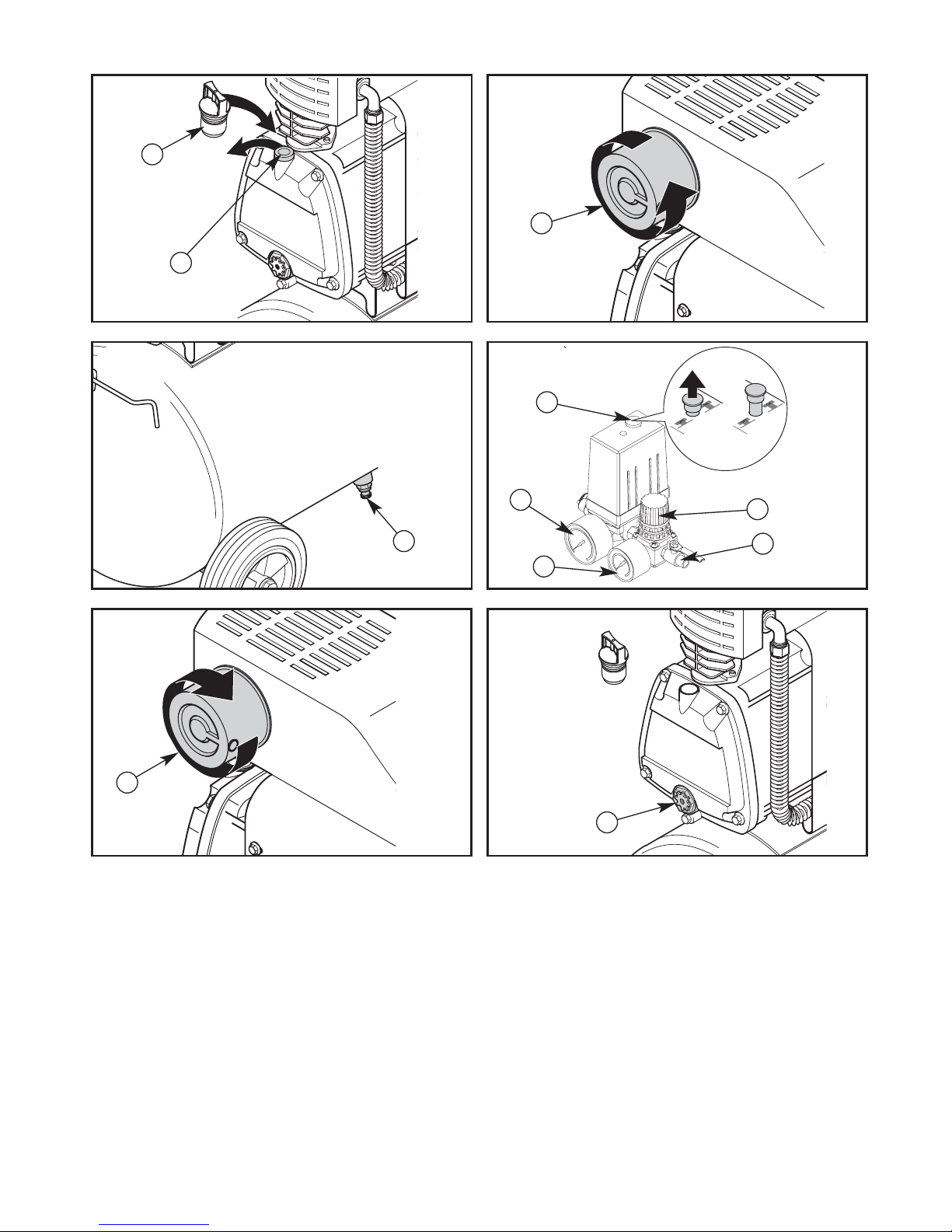
FIG. E
FIG. G
FIG. I
FIG. F
FIG. H
FIG. J
14
11
7
8
5
9
1
6
13
1
12
Page 4

4 • ENGLISH
IMPORTANT
This instruction manual provides important installation, use,
maintenance and safety information and must be at hand at all
times. Before operating this equipment, read this manual and
make sure you understand all of its instructions in order to
avoid personal injuries or damage to your piston compressor.
Warning! Read and understand all instructions. Failure to
follow all instructions listed below, may result in electric shock,
fire and/or serious personal injury.
SAFETY INSTRUCTIONS
If an Air Compressor is improperly used it may
cause physical and material harm. In order to avoid
them, follow the recommendations below:
1. This equipment:
►Has hot, electric and moving parts;
►When connected to electric power, it may turn on
or turn off automatically due to tank’s pressure or
to the tripping of electric protectionelements;
►May cause mechanical or electric interferences
in nearby equipment;
►Must not work in places where non authorized
people, children or animals may have access;
►Requires an authorized person to supervise its
use and maintenance as well as the use of ad
equate individual protection equipment.
►Must be installed and operated in well ventilated
areas and protected against humidity or water
leakage.
2. Never exceed the maximum pressure indicated in
the compressor’s identification tag/sticker.
3. Do not change the pressure switch safety valve factory
adjustment. If any adjustment to the pressure switch is
needed, call the nearest StanleyBlack&Decker Authorized
ServiceCenter.
4. Never weld or carry out maintenance jobs on the
tank, once they may affect its resistance or may hide
more serious problems. In case of leakage, cracks
or deterioration caused by corrosion, stop using
the equipment immediately and get in touch with the
nearest StanleyBlack&Decker Authorized Service Center.
5. Never run the tank above the maximum pressure indicated
on its identification tag.
6. The end user must provide a new inspection of the
Pressure Vessel (tank) to be carried out after 5 (five)
years from the manufacturing date shown in its
identification tag, or when there is chemical or mechanical
damage that may endanger its resistance. The inspection
must be carried out and approved by a duly qualified
engineer (skilled professional), according to local
technical standards and legislation. The next period for
testing will be determined by the responsible engineer
himself. We recommend that the Pressure Vessel (tank)
be exchanged for a new one every 10 (ten) years, or
according to the responsible engineer’s judgment.
7. Air compression is a heat generating process and
parts and accessories are subject to high
temperatures. Therefore, one must be careful
when handling them in order to avoid burns.
8. The produced compressed air is not adequate for
human consumption. To use it for this purpose, it
is necessary to install special filters. Please contact
StanleyBlack&Decker for aditional information.
9. Do not carry out any maintenance while the
compressor is on. Do not clean or touch the
electric components without unplugging the
compressor from the outlet.
10. The refrigeration air intake protecting screen must be
always clean to prevent the propeller from pulling in impurities.
11. Never clean the compressor’s external surface with solvent
(thinner). Always use neutral detergent.
12. Avoid the accumulation of solvents, paints or
other chemicals that may cause damage or
explosion risk to the compressor.
13. Always use an electric extension cord according
to specifications (see Table 2 - Page 21) which
must not be amended. If these recommendations
are not followed, the user may be injured and the
compressor’s electric components may be
damaged, violating the warranty. When necessary,
use a longer air hose.
14. If the equipment presents any irregularities, stop its use
immediately and call the nearest StanleyBlack&Decker
Authorized Service Center.
WELCOME
You have purchased another product with StanleyBlack&Decker
quality standards.
The design, inspection and manufacturing of your
StanleyBlack&Decker tank is based on EN286-1 1998
Attachment 1.It is a mix of high technology and easy use.
INTRODUCTION
WE RECOMMEND READING THIS MANUAL PRIOR
TO USING THIS PRODUCT.
It will help you to optimize product performance, guarantee
safe use and guide you in preventive maintenance.
If there is any problem that cannot be solved by the
information provided in this manual, please contact the
nearest StanleyBlack&Decker Authorized Service Center.
In order to extend the useful life of this coaxial air compressor,
the use of mineral lubricant oil and original parts are highly
recommended.
GENERAL SAFETY RULES
SAVE THESE INSTRUCTIONS
INTRODUCTION
Page 5

ENGLISH • 5
The pressure vessel quality certificate must be presented to
authorities, in case of inspection. Keep it in a safe place along
with the instruction manual.
COMPRESSOR INSPECTION
Inspect for signs of obvious or concealed freight damage.
Report any damage to the delivering freight carrier
immediately. Be sure that all damaged parts are replaced and
any mechanical problems are corrected prior to the operation
of the air compressor. The air compressor serial number is
located on the pump or tank. Please write the serial number in
the space provided in the service section for future reference.
Warning! When using electric product, basic
safety precautions should always be followed to
reduce risk of fire, electric shock, and personal
injury.
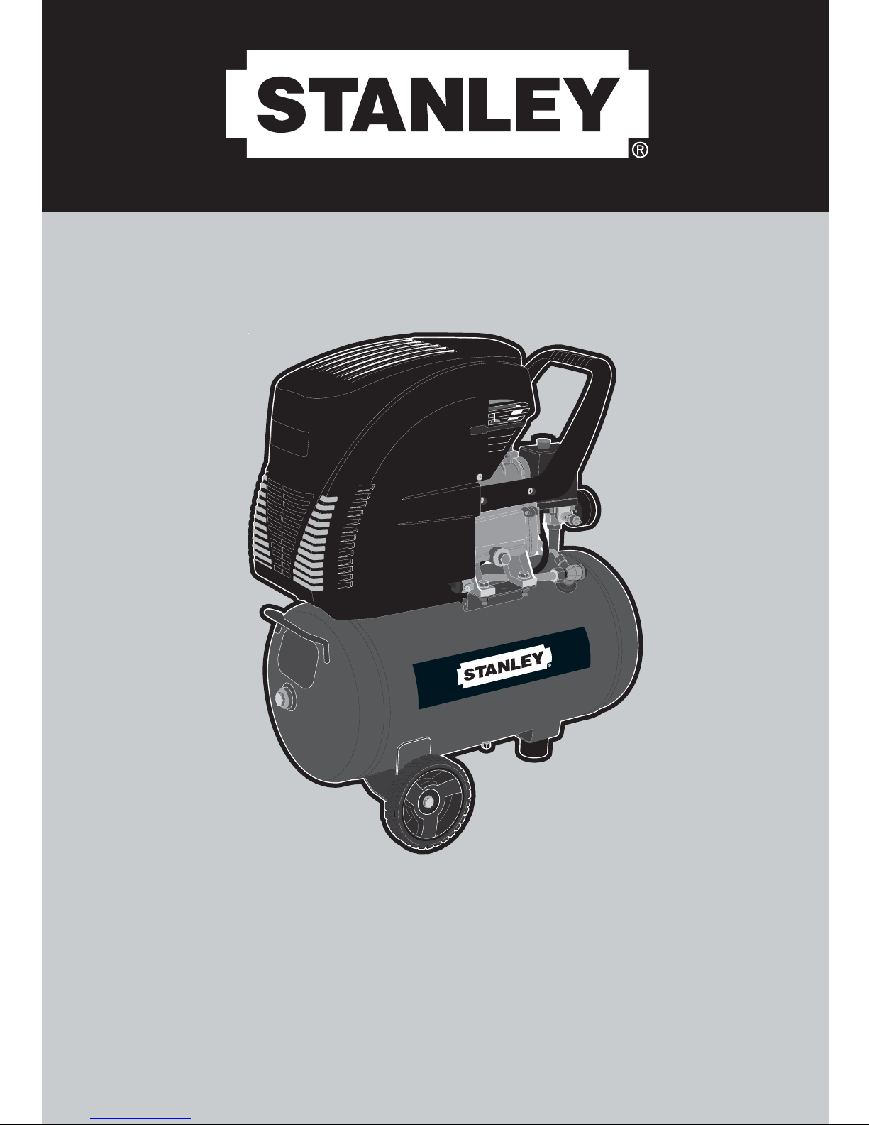
FEATURES (Fig. A and B)
1. Air intake filter housing
2. Compressor pump
3. Pressure vessel
4. Compressed air outlet (quick coupler), air not regulated
5. Compressed air outlet (quick coupler), air regulated
6. Outlet pressure gauge
7. Tank pressure gauge
8. Pressure regulator
9. On/Off switch
10. Safety valve
11. Condensate drain cock
12. Oil drain plug
13. Oil sight glass
14. Dip stick
15. Wheels
TECHNICAL SPECIFICATIONS
NOTE: The tank’s filling up time varies from ± 10%, according
to the installation.
1. Compressor (pump) Unit.- Pull in and compresses
the atmospheric air.
2. Air Tank.- Stores the compressed air.
3. Electric Motor.- Makes the compressor unit run.
4. Pressure Switch.- Controls the operation of compressor
to avoid that the maximum working pressure is surpassed.
See Installation and Electrical Connection Chapter.
5. Safety Valve.-Automatically exhausts the tank in case
the pressure is above the maximum allowed.
6. Check Valve.- Keeps the compressed air inside the tank
avoiding its return when the compressor unit stops.
7. Drain.- Removes the condensed water that accumulates
inside the tank.
8. Pressure Gauge.- Shows the pressure inside the tank
in psi or bar.
9. Pressure Regulator with Valve.- Used to adjust working
pressure on the indicator panel.
10. Protecting Screen.- Protects the rotating parts.
11. Intercooler.- Carries and cools down the compressed air.
12. Air Filter.- Filters atmospheric air impurities that are
sucked by the compressor.
13. Valve.- Controls the compressed air release, connects
KEY PARTS AND FUNCTIONS
CT224 CT250
Weight: 52,8 lbs 24 Kg 70,4 lbs 32 Kg
Height: 24,0 in 625 mm 28,7 in 775 mm
Length: 23,0 in 575 mm 27,1 in 325 mm
Width: 12,2 in 270 mm 12,2 in 730 mm
MODEL
CTS 224 CT250
DISPLACEMENT
MAX. PRESSURE
l/min
50 Hz 140 140
60 Hz 185 185
ROTATION
AIR TANK
psi
120 120
bar
8,4 8,4
rpm
50 Hz 2850 2850
60 Hz 3480 3480
Geom. Volume (L)
24 50
Filin
up time
ELETRIC MOTOR
SINGLE-PHASE
WITH THERMAL
PROTECTOR
Voltage (V)
120/127 or 220 120/127 or 220
HP
1,5 1,5
Max. HP
2,0 2,0
kW
1,1 1,1
Max. kW
1,5 1,5
OIL
CAPACITY
WEIGHT
COLOR REF:
ORANGE ORANGE
Kg
24 32
Lbs
52,8 70,4
Volume (ml)
220 220
50 Hz 1’57 3’55
60 Hz 1’38 3’25
STCT224 STCT250
Weight: 52,8 lbs 24 Kg 70,4 lbs 32 Kg
Height: 24,0 in 625 mm 28,7 in 775 mm
Length: 23,0 in 575 mm 27,1 in 325 mm
Width: 12,2 in 270 mm 12,2 in 730 mm
MODEL
STCT224 STCT250
DISPLACEMENT
MAX. PRESSURE
l/min
50 Hz 140 140
60 Hz 185 185
ROTATION
AIR TANK
psi
115 115
bar
8 8
rpm
50 Hz 2850 2850
60 Hz 3450 3450
Geom. Volume (L)
24 50
Filin
up time
ELETRIC MOTOR
SINGLE-PHASE
WITH THERMAL
PROTECTOR
Voltage (V)
120/127 or 230 120/127 or 230
HP
1,5 1,5
Max. HP
2,0 2,0
kW
1,1 1,1
Max. kW
1,5 1,5
OIL
CAPACITY
WEIGHT
COLOR REF:
ORANGE ORANGE
Kg
24 32
Lbs
52,8 70,4
Volume (ml)
300 300
50 Hz 1’57 3’55
60 Hz 1’38 3’25
CT224 CT250
MODEL
CTS
DISPLACEMENT
MAX. PRESSURE
l/min
50 Hz 140 140
ROTATION
AIR TANK
psi
120 120
bar
8,4 8,4
rpm
50 Hz 2850 2850
60 Hz 3480 3480
Geom. Volume (L)
24 50
Filin
up time
ELETRIC MOTOR
SINGLE-PHASE
WITH THERMAL
PROTECTOR
Voltage (V)
120/127 or 220 120/127 or 220
HP
1,5 1,5
Max. HP
2,0 2,0
kW
1,1 1,1
Max. kW
1,5 1,5
OIL
CAPACITY
WEIGHT
COLOR REF:
ORANGE ORANGE
Kg
24 32
Lbs
52,8 70,4
Volume (ml)
220 220
50 Hz 1’57 3’55
60 Hz 1’38 3’25
STCT224 STCT250
Weight:
Height:
Length:
Width:
MODEL
STCT224 STCT250
DISPLACEMENT
MAX. PRESSURE
l/min
50 Hz 140 140
ROTATION
AIR TANK
bar
8 8
rpm
50 Hz 2850 2850
Geom. Volume (L)
24 50
Filin
up time
ELETRIC MOTOR
SINGLE-PHASE
WITH THERMAL
PROTECTOR
230 230
HP
1,5 1,5
Max. HP
2,0 2,0
kW
1,1 1,1
Max. kW
Voltage (V)
1,5 1,5
OIL
CAPACITY
WEIGHT
COLOR REF:
ORANGE ORANGE
Kg
24 32
Volume (ml)
300 300
50 Hz 1’57 3’55
24 Kg
625 mm
575 mm
270 mm
32 Kg
775 mm
325 mm
730 mm
YELLOW YELLOW
Page 6

the hose nozzle.
14. Oil Drain Plug.- Allows the removal of lubricant oil.
15. Oil Gauge Dipstick.- Shows the oil level and allows its
replacement.
16. Identification Tag/Information Sticker.- Shows the
compressor’s technical data.
17. Tank’s Identification Tag.- Shows the tank’s technical data.
18. Wire with Plug (2P+GR).- Used to connect the
compressor to the electric supply.
19. On/Off Button.- Starts/Shuts off the compressor.
20. Rubber Feet.- Used for the support of the compressor set.
21. Wheels.- Help to move the compressor.
22. Hose Nozzle.- Used to connect the hose to the
compressor, to accessories or hose nozzle (not shown).
Safety Devices (Fig. C)
Safety Valve
The spring safety valve (10) is incorporated into the pressure
switch unit. The safety valve opens if the max. permissible
pressure is exceeded.
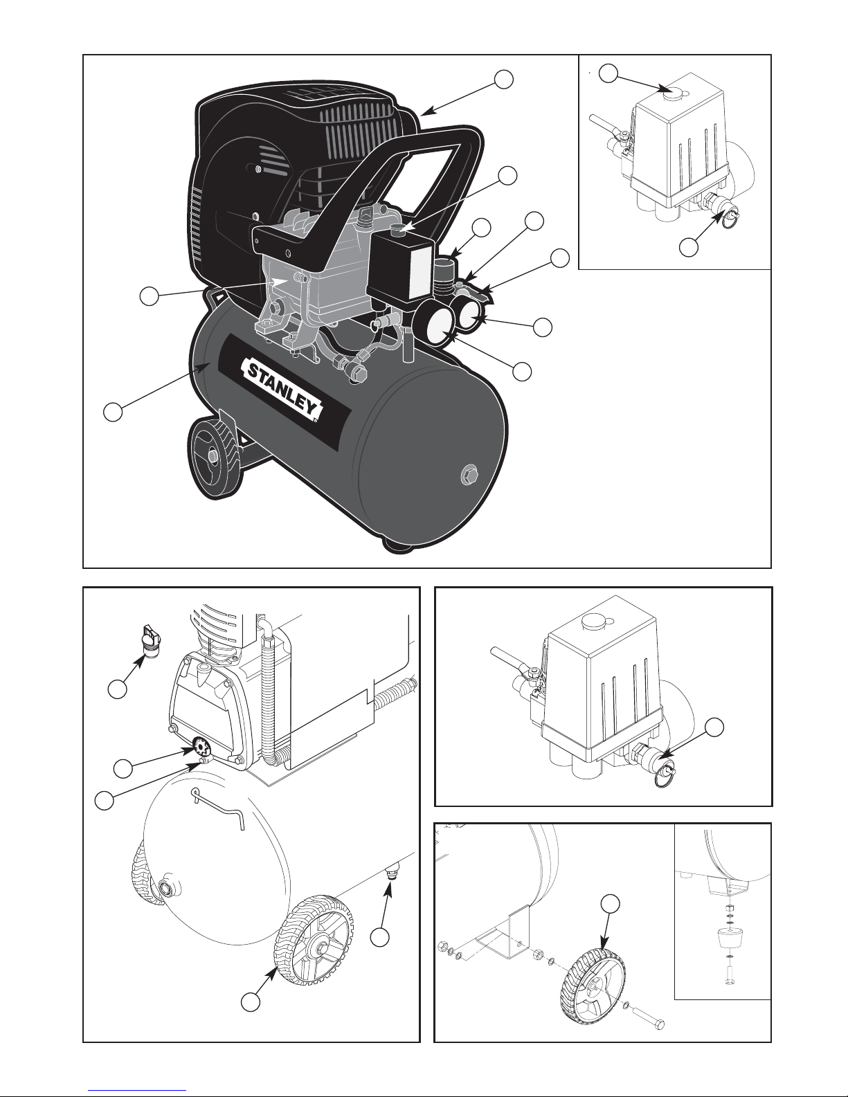
OPERATION
Prior to Initial Operation
Install Wheels (Fig. D)
1. Install wheels (15) as illustrated.
2. Install rubber feet as illustrated.
Insert Dip Stick (Fig. E)
1. Remove the plug (12) from the crankcase.
2. Substitute the plug with the dip stick (14) supplied.
The plug prevents oil from leaking from the crankcase during
shipping. Keep plug for future use.
Install Air Intake Filter (Fig. F).
1. Remove plug from air intake of compressor pump housing.
Keep plug for future use.
2. Screw air filter (1) supplied on air intake.
Check Condensate Drain (Fig. G)
► Check to see that the condensate drain's screw (11)
is closed.
INSTALLATION OF THE AIR NETWORK
1. Assembly: Remove the product from the packaging and
rubber feet.
2. Location: Install the compressor in a covered, well ventilated
area, free of dust, gases, toxic gases, humidity or any other
kind of pollution. The ambient temperature recommended
during work is: minimum of 5°C (41°F) and maximum of
40°C (104°F). In order to avoid damage to the compressor,
operate it on a level foundation.
2.1 Compressor’s Installation: When this compressor
model is coupled to a compressed air network, the
connection must be made by a hose or expandable
joints so that the charges, thermal expansion, piping’s
weight, mechanical and thermal shocks or obstructions
are not transmitted to the air receiver. The air receiver
may be damaged if these warnings are not observed.
3. Position: Keep a minimum distance of 800 mm (32") from
any obstacle, to allow good ventilation during operation and
to make maintenance easier.
4. Quality of Compressed Air: For services in which the air
must be free of oil or dust particles, the installation of special
air filters. Please contact the nearest StanleyBlack&Decker
Authorized Service Center for information.
5. Electrical Connection:
5.1 Look for a specialized technician to evaluate
the electrical supply and to select the adequate protection
and input devices Electrical Wiring Diagram.
Electrical Wiring Diagram
Grounding Instructions: This product must be grounded
to reduce the risk of an electric shock.
Warning! The incorrect installation of the grounding wire
connector may result in an electric shock. If it is necessary to
replace or repair both the cable and the connector, do not
connect the grounding wire to the terminal of the flat blade.
The green cable, with or without yellow stripes, is the rounding
cable. In case of doubts regarding the grounding information
or whether the product is properly grounded, make sure you
contact a qualified electrician to verify the connections.
6 • ENGLISH
P
F1
GROUND
Tension
Supplies
PLUG2P+GR
OR WIRE
Customer's responsibility
M
1~
Phase
N
Neutral
F1 Fuse type "D" or "NH"
(See Table 2 - Page 5)
P Pressure switch
M Electric motor
ENCHUFE CON
ATERRAMENTO
ENCHUFE
A TIERRA
ESPIGA
A TIERRA
ESPIGAS DE
ATERRAMENTO
ESPIGAS DE ATERRAMENTO
GROUNDED
OUTLET
GROUNDED OUTLET
GROUNDED
OUTLET
GROUNDING
PIN
GROUNDING
PIN
GROUNDING PIN
TOMADA COM
CONEXÃO DE
ATERRAMENTO
PINO DE
ATERRAMENTO
Page 7

6. Important: A compressor with good dimensions (with
pressure switch) will have roughly six (6) starts per hour.
See “Instruction Troubleshooting Guide” (page. 9).
7. Electric Motor Warranty: The electric motor warranty will
only be granted if the installation instruction are followed
according to diagram “Electrical Wiring Diagram”.
8. Before plugging the equipment to the electric supply, check
if voltage indicated in the supply wire’s tag matches the
local voltage.
Table 2.- Orientation Data for Conductors and Fuses
Note:
► The energy supply must not present voltage changes
over ± 10%.
► Voltage drop caused by start up must not be over 10%
► For your safety, the installation must have a grounding
conductor to avoid electric shocks.
► INSTALLATION EXPENSES ARE THE PURCHASER’S
RESPONSIBILITY.
Generating Compressed Air (Fig. H)
1. Start compressor (9) and wait until the max. tank pressure
is reached (compressor shuts off).
The tank pressure is indicated by the tank pressure gauge (7).
2. Set pressure regulator (8) to required working pressure.
The current working pressure is indicated by the regulated
pressure gauge (6).
Caution! The regulated pressure may not be set higher
than the max. working pressure of the connected air tools.
3. Connect air hose to compressed air outlet (5).
4. Connect air tool. You are now ready to work with the air tool.
5. Switch the compressor OFF (9), if you do not continue
working immediately afterwards. Unplug after switching OFF.
CARE AND MAINTENANCE
Danger! Prior to all servicing:
► Switch Off.
► Unplug.
► Wait until the compressor has come to a complete stop.
► Ensure the compressor and all air tools and accessories
connected to it are relieved from pressure.
► Let the device and all air tools and accessories used cool off.
After all servicing:
► Check to see that all safety devices are operational.
► Make sure that no tools or other parts remain on
or in the machine.
► Repair and maintenance work other than described in this
section must only be carried out by qualified specialists.
Periodic Maintenance
Prior to Each Use:
► Check air hoses for damage, replace if necessary.
► Check all screwed connections for tightness, tighten
if necessary.
► Check power supply cable for damage, if necessary have
replaced by a qualified electrician.
Every 50 Operating Hours (Fig. G, I and J)
► Check air filter element (1) of compressor pump,
clean if necessary.
► Check oil level of pump at oil sight glass (14),
top up oil if necessary.
► Drain condensate from pressure vessel (11).
Every 250 Operating Hours
► Replace air intake filter element of compressor pump.
Every 500 Operating Hours
► Drain oil and fill with fresh oil.
Every 1000 Operating Hours
► Have unit serviced by an authorized service station.
This will extent the compressor's service life considerably.
Machine Storage
1. Switch unit OFF and unplug.
2. Release pressure from tank and all connected air tools.
3. Store machine in such way that it cannot be started
by unauthorized persons.
Caution! Do not store machine unprotected outdoors or in
damp environment.
Do not lay device on its side for transportation or storing.
MAINTENANCE
Your tool has been designed to operate over a long period of
time with a minimum of maintenance. Continuous satisfactory
operation depends upon proper tool care and regular cleaning.
Warning! Before performing any maintenance, switch off
and unplug the tool.
► Regularly clean the ventilation slots in your tool using
a soft brush or dry cloth.
► Regularly clean the motor housing using a damp cloth.
Do not use any abrasive or solvent-based cleaner.
PROTECTING THE ENVIRONMENT
Separate collection. This product must not be
disposed of with normal household waste. Should
you find one day that your Black & Decker product
needs replacement, or if it is of no further use to you,
ENGLISH • 7
MOTOR
POWER
(HP)
ELECTRICAL
VOLTAGE
(V)
CONDUCTOR
(mm)
2
FUSE
(A)
MAX. DIST. (m/in)
VOLTAGE DROP (%)
35207 / 273
27 / 1053
2.5
mm
2
AWG
1.51315
120/127
230
2.0 MAX.
POTENCIA
MOTOR
(HP)
TENSIÓN
RED
(V)
CONDUCTOR
(mm)
2
FUSIBLE
(A)
DIST. MÁX. (m)
CAIDA TENSIÓN (%)
35
20
7
27
2,5
1,5
120/127
220
2,0 Máx.
POTÊNCIA
MOTOR
(HP)
TENSÃO
REDE
(V)
CONDUTOR
(mm)
2
FUSÍVEL
(A)
DIST. MÁX. (m)
QUEDA TENSÃO (%)
35
20
7
27
2,5
1,5
120/127
220
2,0 Max.
MOTOR
POWER
(HP)
ELECTRICAL
VOLTAGE
(V)
CONDUCTOR
(mm)
2
FUSE
(A)
MAX. DIST. (m/in)
VOLTAGE DROP (%)
35
20
7 / 273
27 / 1053
2.5
mm
2
AWG
1.51315
120/127
230
2.0 MAX.
MOTOR
POWER
(HP)
ELECTRICAL
VOLTAGE
(V)
CONDUCTOR
(mm)
2
FUSE
(A)
MAX. DIST. (m/in)
VOLTAGE DROP (%)
mm
2
AWG
2027 / 10531.5 152302.0 MAX.
Page 8

do not dispose of it with household waste. Make this
product available for separate collection.
Separate collection of used products and packaging
allows materials to be recycled and used again.
Re-use of recycled materials helps prevent
environmental pollution and reduces the demand for
raw materials. Local regulations may provide for
separate collection of electrical products from the
household, at municipal waste sites or by the retailer
when you purchase a new product.
SERVICE INFORMATION
Black & Decker offers a full network of company-owned
and authorized service locations. All StanleyBlack&Decker
Service Centers are staffed with trained personnel to provide
customers with efficient and reliable power tool service.
For more information about our authorized service centers
and if you need technical advice, repair, or genuine factory
replacement parts, contact the StanleyBlack&Decker location
nearest you.
8 • ENGLISH
Air Flow Rate @ 40 PSI - 50Hz SCFM - L/min 3.7 - 105 3.7 - 105
Air Flow Rate @ 90 PSI - 50Hz SCFM - L/min 2.6 - 74 2.6 - 74
Air Flow Rate @ 115 PSI - 50Hz SCFM - L/min 2.4 - 68 2.4 - 68
Operating Pressure (Max.) Bar 8 8
Amounts of Cylinders 1 1
Number of Stages 1 1
Max. Service/Ambient Temperature ** °C + 40 + 40
Min. Service/Ambient Temperature ** °C + 5 + 5
Air Tank Volume L 24 50
Air Outlet Amounts 1 1
Rotation - 50Hz rpm 2850 2850
Engine Power - Max. HP 2 2
Connection Voltage - 50Hz V 2
30 230
Rated Current - 50Hz A 6.4 6.4
Fuse Protection See table 2 pg. 21
Max. Total Length When Extensions Are Used See table 2 pg. 21
Standard motor protection IP 20 20
Weight K g 23.8 32.5
Dimensions m m (H x W x L)
575 x 270 x 625 775 x 325 x 730
Amount of Oil for Change L approx. 0.3 approx. 0.3
Sound Level dB(A) 91 93
All technical data refers to an ambient temperature of 20 °C.
**)
The service life of some components, for instance the seal of the anti-surge valve, is substantially reduced when the compressor works
at high temperatures (max. and higher service/storage temperature).
**) There is the risk of freezing for the condensation in the pressure tank when temperatures are below the min. service/storage temperature.
SPECIFICATIONS
STCT224 STCT250
Page 9

COD
POSSIBLE CAUSE POSSIBLE SOLUTION
1
2
3
4
5
6
7
8
9
10
Voltage drop or electrical
supply is out.
Damaged electric motor.
Tank is full of air.
Installation fuse has burned out.
Check valve does not seal
because of impurities.
The demand is above
the compressor’s capacity.
Thermal protector tripped.
Filter clogged.
Air leakage in the compressor.
High ambient temperature
(Max. 40˚C or 104˚F)
Check the installation and/or wait
for the electrical supply stabil
ization.
Send it to the nearest
StanleyBlack&Decker
Authorized Service Center.
Electric motor will start
as soon as the pressure
in the tank decreases.
Find out the burning cause
Page. 21
Send the compressor to the
nearest
StanleyBlack&Decker
Authorized Service Center
Check the compressor’s capacity.
Turn compressor off, wait for 5 (five)
min. and reset the protector. If tripping
is frequent, look for the nearest
Replace it.
Re-fasten bolts and/or fitti
ngs.
Improve local conditions.
COD
POSSIBLE CAUSE POSSIBLE SOLUTION
1
2
3
4
5
6
7
8
9
10
11
12
13
14
15
16
17
18
19
20
Voltage drop or electrical
supply is out.
Damaged electric motor.
Tank is full of air.
Installation fuse has burned out.
Check valve does not seal
because of impurities.
The demand is above
the compressor’s capacity.
Thermal protector tripped.
Filter clogged.
Air leakage in the compressor.
High ambient temperature
(Max. 40˚C or 104˚F)
Valve plate joint is broken.
Wrong oil or low oil level.
Carbonized valve plate.
Deficient or inadequate
electrical supply.
Operating in a non-adequate
environment.
The oil change did not occur at
the recommended interval.
Loose fastening elements.
Continuous air leakage through
pressure switch’s relief valve when
compressor shuts off.
Excess water in the tank.
Too much dust and paint
on the compressor.
Check the installation and/or wait
for the electrical supply stabilization.
Send it to the nearest Black&Decker
Authorized Service Center.
Electric motor will start
as soon as the pressure
in the tank decreases.
Find out the burning cause
(See Table 2 - Pág. 21)
Send the compressor to the
nearest Black&Decker
Authorized Service Center
Check the compressor’s capac
ity.
Turn compressor off, wait for 5 (five)
min. and reset the protector. If tripping
is frequent, look for the nearest
Black&Decker Authorized Center.
Replace it.
Re-fasten bolts and/or fittings.
Improve local conditions.
Look for the nearest
StanleyBlack&Decker
Authorized Center.
Change oil.
Clean it every 1000 working hours
or 12 months at your nearest
Have a specialized technician
check it.
Improve local conditions.
See “Care and Maintenance”
Page 21
Find and re-fasten them.
Send compressor to the nearest
Drain the tank through the drain
as indicated in Fig. B - Page 2
Clean the compressor externally.
TROUBLESHOOTING GUIDE
This section provides a list of the more frequently encountered malfunctions, their causes and corrective actions. The operator or
maintenance personnel can perform some corrective actions, and others may require the assistance of a qualified
StanleyBlack&Decker technician.
ENGLISH 9
Motor does not start or does not restart
(Do not insist to start the motor. Do it only after
you have discovered and eliminated the cause
of the problem)
1, 2, 3, 4, 5, 7, 14, 15, 22
Reduce air production
(Pressure gauge keeps showing a lower pressure
than that of the job)
6, 8, 9, 10, 11, 13, 16
The compressor unit overheats
5, 6, 10, 11, 12, 13, 16, 20, 25
Electric motor overheats
5, 7, 10
Premature wear of the compressor unit
internal parts
6, 9, 10, 12, 15, 16, 23
Abnormal noise or vibration
15, 16, 17
Tank pressure increases quickly or too frequent
starts (The normal number of starts is roughly
6 an hour)
19, 24
Problem
Code
Problem
Code
Problem
Code
Problem
Code
Problem
Code
Problem
Code
Problem
Code
Problem
Code
Problem
Code
Problem
Code
Problem
Code
Problem
Code
Problem
Code
High temperature of the compressed air
5, 6, 8, 9, 10, 11, 12, 13, 20
Compressor operate ininterruptedly
6, 8, 13, 25
Excessive consumption of lubricating oil
(Compressors usually use more oil in the first 200
working hours until rings are smoothly adjusted)
6, 10, 12
Lubricant oil with unusual color
10, 15, 16, 21
Insufficient pressure for required work
15, 18, 24
Air leakage through relief valve of pressure switch
or compressor unit (when assembled), with
compressor operating from more than 1 (one)
minute (valve closes above 20 psi (1.3 bar))
25
StanleyBlack&Decker Authorized Center
StanleyBlack&Decker Authorized Center
StanleyBlack&Decker Authorized
Service Center.
Page 10

10 ENGLISH
20
21
22
23
24
25
Too much dust and paint
on the compressor.
Water is mixed with the oil
(milky coloration).
Ambient temperature below minimum
recommended 5˚C (41˚F).
Operating too long below
pressure of 60 psi (4.0 bar).
Pressure regulator valve not adjusted
(Fig. H )
Relief valve not seal because
of impurities.
as indicated in Fig. B - Page 2
Clean the compressor externally.
Change the lubricant oil and run
your pressure compressor for
15 min, at a maximum pressure of
100 psi (7.0 bar). This will remove
any internal condensation signs
inside pump.
Run the equipment above 5˚C
(41˚F)
Compressed air consumption
higher than compressor’s flow.
Adjust it.
Send compressor to the nearest
StanleyBlack&Decker Authorized Center
 Loading...