

Page 1
Errigal Solid Fuel Boiler/Non Boiler Range
SAFETY NOTICE
PLEASE READ THIS ENTIRE MANUAL BEFORE YOU INSTALL AND USE YOUR NEW COOK STOVE. FAILURE TO FOLLOW INSTRUCTIONS MAY RESULT IN PROPERTY DAMAGE,
BODILY INJURY OR EVEN DEATH. SAVE THESE INSTRUCTIONS FOR FUTURE REFERENCE.
IF THIS APPLIANCE IS NOT PROPERLY INSTALLED, A HOUSE FIRE MAY RESULT. FOR YOUR SAFETY,
FOLLOW THE INSTALLATION DIRECTIONS. CONTACT LOCAL BUILDING OR FIRE OFFICIALS ABOUT
RESTRICTIONS AND INSTALLATION INSPECTION REQUIREMENTS IN YOUR AREA.
THIS APPLIANCE MUST BE CONNECTED TO A LISTED, HIGH-TEMPERATURE RESIDENTIAL TYPE AND
BUILDING HEATING APPLIANCE CHIMNEY OR AN APPROVED MASONRY CHIMNEY WITH FLUE LINER.
THE COMPLETE INSTALLATION MUST BE DONE IN ACCORDANCE WITH CURRENT STANDARDS AND
LOCAL CODES. IT SHOULD BE NOTED THAT THE REQUIREMENTS AND THESE PUBLICATIONS MAY
BE SUPERSEDED DURING THE LIFE OF THIS MANUAL.
MANUFACTURED BY: WATERFORD STANLEY (MARKETING) LTD., BILBERRY, WATERFORD,
IRELAND.
ASSEMBLY INSTALLATION AND OPERATING INSTRUCTIONS
Page 2

1
TABLE OF CONTENTS
PAGE
1. Introduction . . . . . . . . . . . . . . . . . . . . . . . . . . . . . . . . . . . . . . . . . . . . . . . . . . . . . . . . . . . 2
2. Specification . . . . . . . . . . . . . . . . . . . . . . . . . . . . . . . . . . . . . . . . . . . . . . . . . . . . . . . . . . 3
3. Technical Data. . . . . . . . . . . . . . . . . . . . . . . . . . . . . . . . . . . . . . . . . . . . . . . . . . . . . . . . . 3
4. Installation . . . . . . . . . . . . . . . . . . . . . . . . . . . . . . . . . . . . . . . . . . . . . . . . . . . . . . . . . . . . 3
5. Pre-Installation Assembly . . . . . . . . . . . . . . . . . . . . . . . . . . . . . . . . . . . . . . . . . . . . . . . . 4
6. Top Flue Exit . . . . . . . . . . . . . . . . . . . . . . . . . . . . . . . . . . . . . . . . . . . . . . . . . . . . . . . . . . 5
7. Rear Flue Exit . . . . . . . . . . . . . . . . . . . . . . . . . . . . . . . . . . . . . . . . . . . . . . . . . . . . . . . . . 5
8. Flues . . . . . . . . . . . . . . . . . . . . . . . . . . . . . . . . . . . . . . . . . . . . . . . . . . . . . . . . . . . . . . . . 5
9. Flue Pipes . . . . . . . . . . . . . . . . . . . . . . . . . . . . . . . . . . . . . . . . . . . . . . . . . . . . . . . . . . . . 5
10. Flue Cleaning . . . . . . . . . . . . . . . . . . . . . . . . . . . . . . . . . . . . . . . . . . . . . . . . . . . . . . . . . 6
11. Chimney . . . . . . . . . . . . . . . . . . . . . . . . . . . . . . . . . . . . . . . . . . . . . . . . . . . . . . . . . . . . . 6
12. Use of Existing Flues & Chimneys . . . . . . . . . . . . . . . . . . . . . . . . . . . . . . . . . . . . . . . . . 6
13. Location. . . . . . . . . . . . . . . . . . . . . . . . . . . . . . . . . . . . . . . . . . . . . . . . . . . . . . . . . . . . . . 6
14. Floor Protection. . . . . . . . . . . . . . . . . . . . . . . . . . . . . . . . . . . . . . . . . . . . . . . . . . . . . . . . 6
15. Clearance to Combustibles . . . . . . . . . . . . . . . . . . . . . . . . . . . . . . . . . . . . . . . . . . . . . . . 7
16. Ventilation & Combustion Air Requirements . . . . . . . . . . . . . . . . . . . . . . . . . . . . . . . . . . 7
17. Smoke Spillage Test . . . . . . . . . . . . . . . . . . . . . . . . . . . . . . . . . . . . . . . . . . . . . . . . . . . . 7
18. Plumbing . . . . . . . . . . . . . . . . . . . . . . . . . . . . . . . . . . . . . . . . . . . . . . . . . . . . . . . . . . . . 8
19. Heating System. . . . . . . . . . . . . . . . . . . . . . . . . . . . . . . . . . . . . . . . . . . . . . . . . . . . . . . . 8
20. Boiler Output . . . . . . . . . . . . . . . . . . . . . . . . . . . . . . . . . . . . . . . . . . . . . . . . . . . . . . . . . . 8
21. Gravity Circuit . . . . . . . . . . . . . . . . . . . . . . . . . . . . . . . . . . . . . . . . . . . . . . . . . . . . . . . . . 8
22. Heating . . . . . . . . . . . . . . . . . . . . . . . . . . . . . . . . . . . . . . . . . . . . . . . . . . . . . . . . . . . . . . 8
23. Pipe Fittings . . . . . . . . . . . . . . . . . . . . . . . . . . . . . . . . . . . . . . . . . . . . . . . . . . . . . . . . . . 8
24. Water Circuit Temperature . . . . . . . . . . . . . . . . . . . . . . . . . . . . . . . . . . . . . . . . . . . . . . . 8
25. Care For Your Central Heating System . . . . . . . . . . . . . . . . . . . . . . . . . . . . . . . . . . . . . 9
26. Injector Tee . . . . . . . . . . . . . . . . . . . . . . . . . . . . . . . . . . . . . . . . . . . . . . . . . . . . . . . . . . . 9
27. Draining. . . . . . . . . . . . . . . . . . . . . . . . . . . . . . . . . . . . . . . . . . . . . . . . . . . . . . . . . . . . . . 9
28. General Maintenance . . . . . . . . . . . . . . . . . . . . . . . . . . . . . . . . . . . . . . . . . . . . . . . . . . . 9
29. Fuels . . . . . . . . . . . . . . . . . . . . . . . . . . . . . . . . . . . . . . . . . . . . . . . . . . . . . . . . . . . . . . . . 9
30. Lighting The Fire . . . . . . . . . . . . . . . . . . . . . . . . . . . . . . . . . . . . . . . . . . . . . . . . . . . . . . . 9
31. Refuelling . . . . . . . . . . . . . . . . . . . . . . . . . . . . . . . . . . . . . . . . . . . . . . . . . . . . . . . . . . . . 10
32. Controlling The Fire . . . . . . . . . . . . . . . . . . . . . . . . . . . . . . . . . . . . . . . . . . . . . . . . . . . . 10
33. Overnight Burning . . . . . . . . . . . . . . . . . . . . . . . . . . . . . . . . . . . . . . . . . . . . . . . . . . . . . 10
34. De-Ashing . . . . . . . . . . . . . . . . . . . . . . . . . . . . . . . . . . . . . . . . . . . . . . . . . . . . . . . . . . . 10
35. Disposal of Ashes . . . . . . . . . . . . . . . . . . . . . . . . . . . . . . . . . . . . . . . . . . . . . . . . . . . . . 10
36. Main Oven . . . . . . . . . . . . . . . . . . . . . . . . . . . . . . . . . . . . . . . . . . . . . . . . . . . . . . . . . . . 11
37. The Hotplate. . . . . . . . . . . . . . . . . . . . . . . . . . . . . . . . . . . . . . . . . . . . . . . . . . . . . . . . . . 11
38. Use of Tools . . . . . . . . . . . . . . . . . . . . . . . . . . . . . . . . . . . . . . . . . . . . . . . . . . . . . . . . . . 11
39. Hints on Fire Safety . . . . . . . . . . . . . . . . . . . . . . . . . . . . . . . . . . . . . . . . . . . . . . . . . . . . 11
40. Over Firing . . . . . . . . . . . . . . . . . . . . . . . . . . . . . . . . . . . . . . . . . . . . . . . . . . . . . . . . . . . 11
41. Cleaning Instructions . . . . . . . . . . . . . . . . . . . . . . . . . . . . . . . . . . . . . . . . . . . . . . . . . . . 12
42. Cleaning of Mild Steel Parts. . . . . . . . . . . . . . . . . . . . . . . . . . . . . . . . . . . . . . . . . . . . . . 13
43. Cleaning The Ovens . . . . . . . . . . . . . . . . . . . . . . . . . . . . . . . . . . . . . . . . . . . . . . . . . . . 13
44. Cleaning The Hotplate . . . . . . . . . . . . . . . . . . . . . . . . . . . . . . . . . . . . . . . . . . . . . . . . . . 13
45. Vitreous Enamel Cleaning . . . . . . . . . . . . . . . . . . . . . . . . . . . . . . . . . . . . . . . . . . . . . . . 13
46. Exploded View . . . . . . . . . . . . . . . . . . . . . . . . . . . . . . . . . . . . . . . . . . . . . . . . . . . . . . . . 14
Page 3
INTRODUCTION
Congratulations on purchasing this fine Irish made Solid Fuel cooker which is built to exacting standards.
Please read the following information before operating this product.
This appliance is hot while in operation and retains its heat for a long period of time after use. Children,
aged or infirm persons should be supervised at all times and should not be allowed to touch the hot
working surfaces while in use or until the appliance has thoroughly cooled.
As manufacturers and suppliers of cooking and heating appliances, we take every possible care to ensure as
reasonably practicable, that these appliances are so designed and constructed as to meet the general safety
requirement when properly used and installed.
The complete installation must be done in accordance with current Standards and Local Codes. It should be
noted that the requirements and these publications may be superseded during the life of this manual.
IMPORTANT NOTICE: Any alteration to this appliance that is not approved in writing by Waterford Stanley will
render the guarantee void.
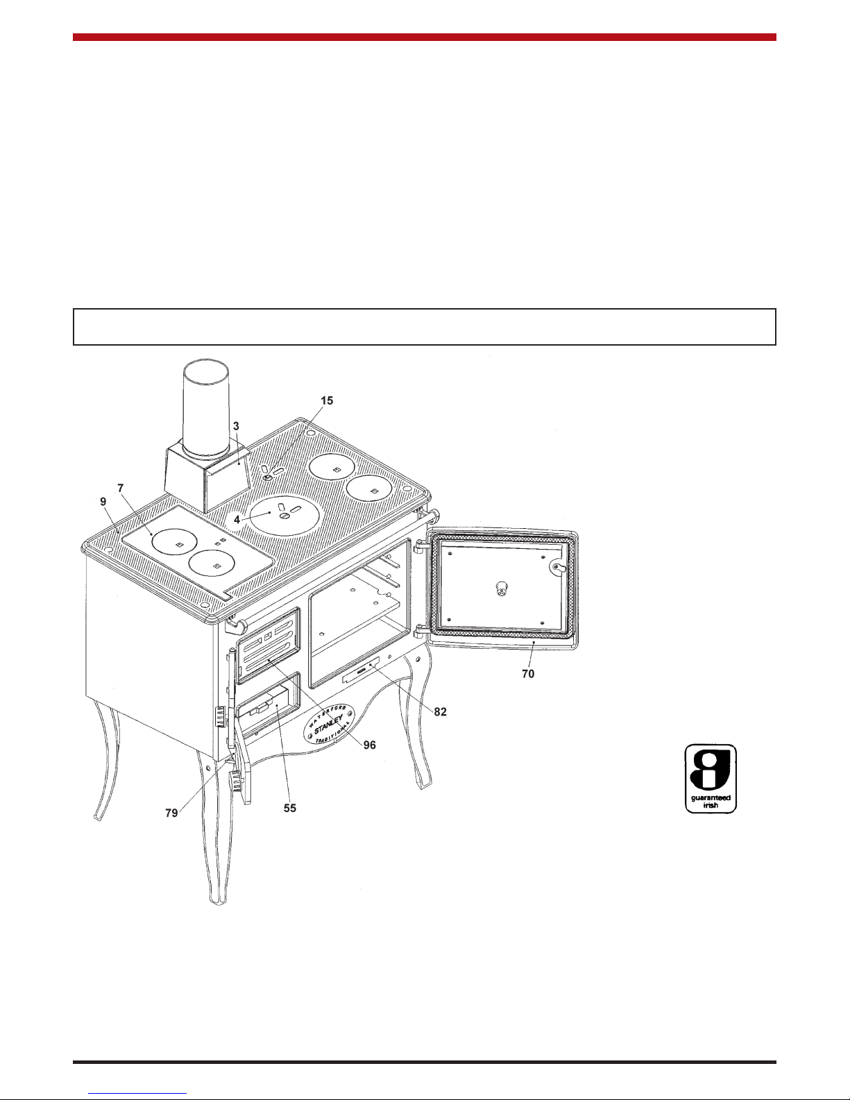
Fig.1
2
3. Bonnet Door
7. Hot Plate
9. Hob
15. Direct Damper
18. Oven Damper
55. Ash Pan
70. Oven Door
79. Spin Valve
82. Base Cleaning Door
96. Fire Fence
Page 4
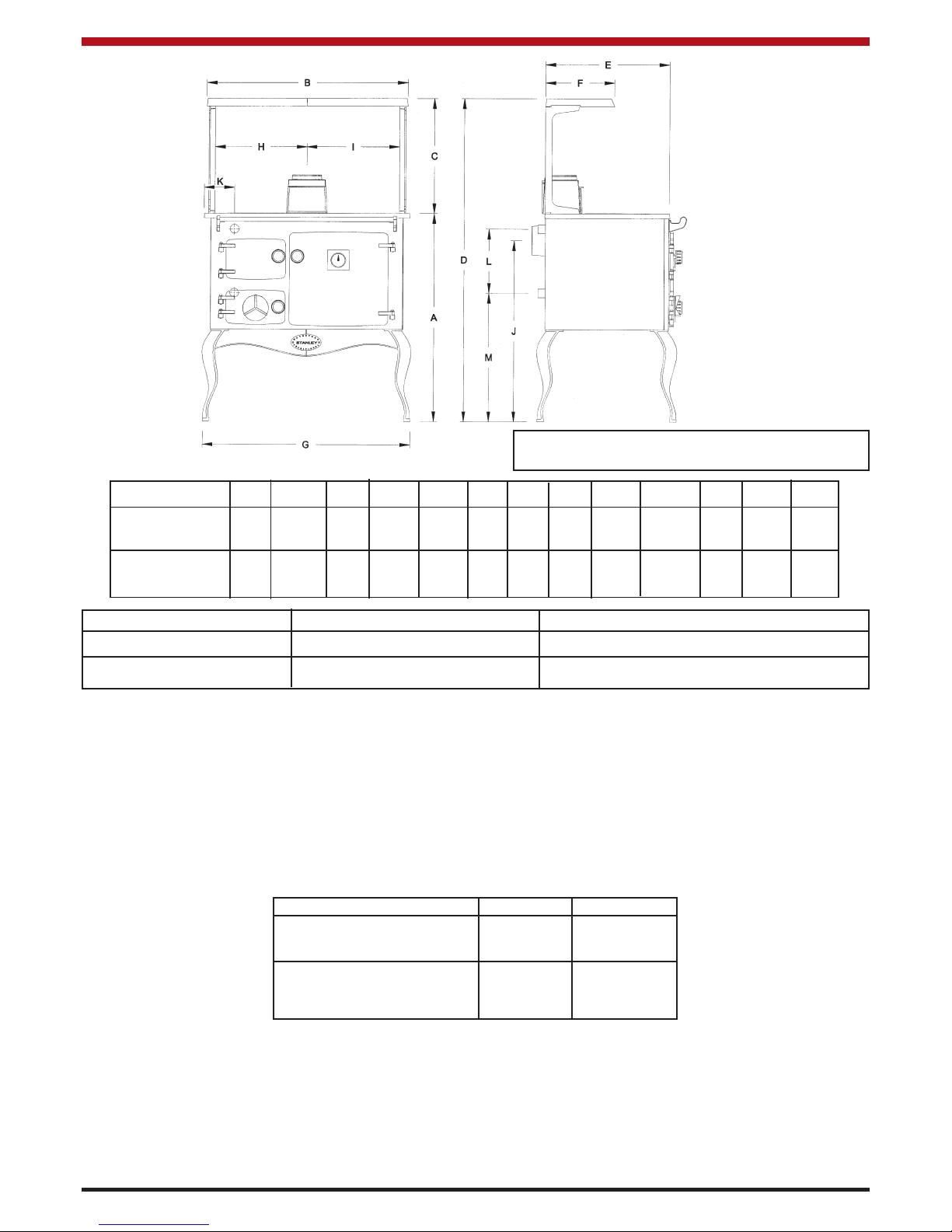
DIMENSIONS ABCDEFGHIJKLM
METRIC 880 905 508 1388 565 290 950 452 452 725 130 260 565
(millimetre)
IMPERIAL
34
5
/8 355/8 20 545/8 221/4 111/2 372/5 173/4 173/4 2811/20 5
1
/8
10
1
/4 221/4
(inches)
FEATURE METRIC IMPERIAL
HOT PLATE 911.25 cm
2
144 in
2
OVEN 400W x 330H x 400D 15
3
/4W x 13H x 153/4D
TECHNICAL DATA
CHIMNEY DRAUGHT: 0.06” - 0.10” wg. (1.52mm - 2.54mm)
FLUE DIAMETER: 5” (127mm)
BOILER TAPPINGS: 1” BSP (28mm)
TEST PRESSURE OF BOILER (Where applicable): 40 PSI (2.75 Bar)
OPERATING TEMPERATURE LIMIT: 96
0
C 2050F
COOKER WEIGHT: 263 Kgs (579 lbs)
SPACE HEATING: 3 kW’s (10, 000) Btu’s
Fig.2
NOTE: Dimensions stated below may be subject
to a slight +/- variation.
All technical data are taken under laboratory conditions and may vary in use, flue draught conditions will effect
performance
SPECIFICATION
BOILER TYPE 47K DHW
BOILER CAPACITY: 7.5 LTRS 3.2 LTRS
MAX OUTPUT TO WATER: 47,000 Btu 10,000 Btu
(13.77 kW) (2.9 kW)
INSTALLATION
When installing, operating and maintaining a solid fuel heater, respect basic standards of fire safety. Read
these instructions carefully before commencing the installation. Failure to do so may result in damage to persons and property. Consult your local municipal office, Fire Department and your insurance representative to
determine what regulations are in force.
3
Page 5
1. Remove packing strip from the top of
the range. Place the sheet steel back
plate to one side. Remove all loose
components from the top of the range
and firebox and the oven. Remove the
oven door. Spread the components on
the floor so you can identify them easily.
2. Place strong supports about 458mm (13”)
high behind the range. Space the supports
behind it and lay the cooker on its back.
(See Fig.4)
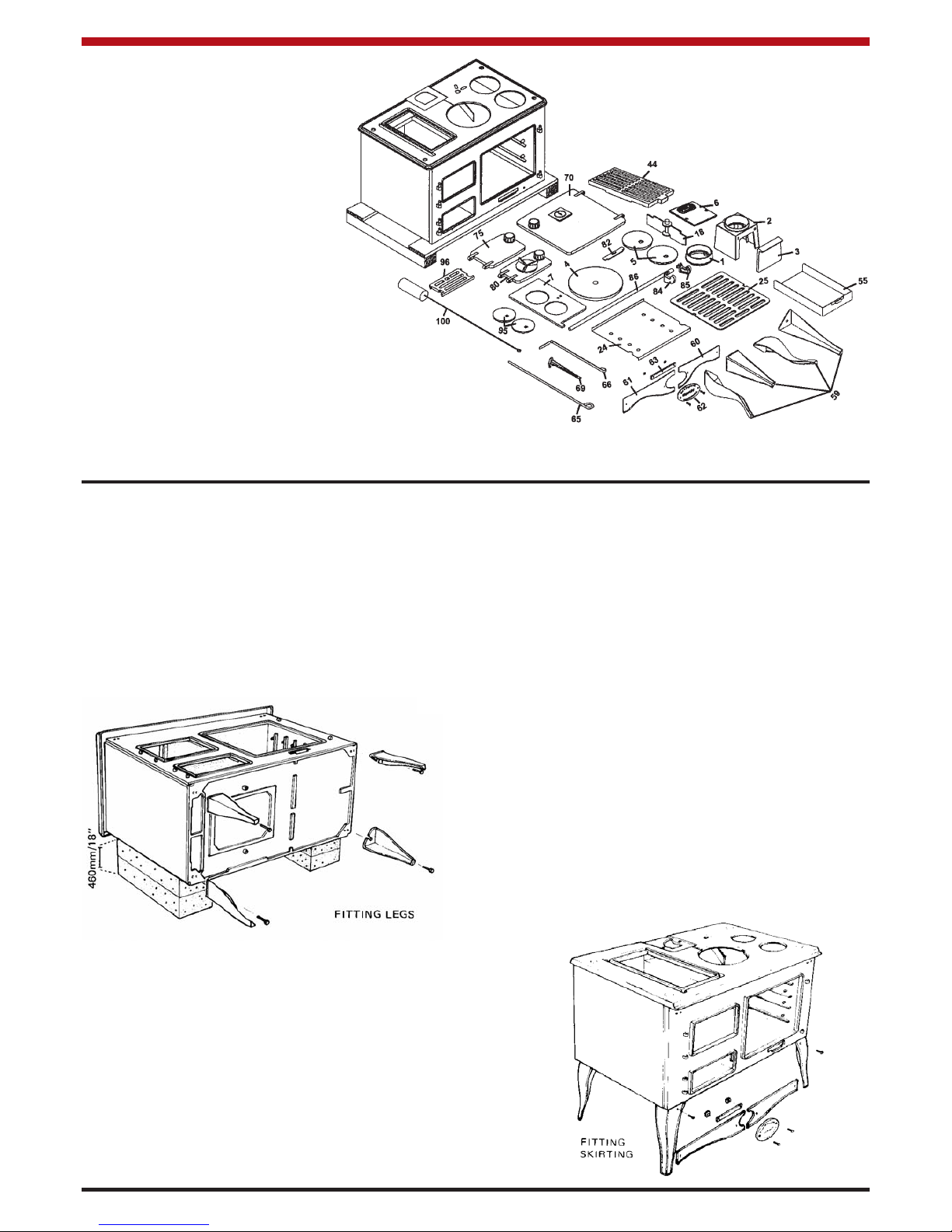
3. Fit the four legs (Part no. 59) to the four base
corners (Part no. 58) using the hexagon-head
bolts and washers. Note that each of the front
legs has a screw hole in the front.
4. Lift the range off the supports. Stand it upright
without putting any strain on the legs.
5. Join the two sections of the front plinth together (Part Nos. 60 and 61) by screwing the name
plate (Part No. 62) and the plinth joining clip
(Part No. 63) into position between the two
sections and secure the two sections tightly to
the name plate.
6. Fit the complete plinth under the front of the
range inside the front legs using a screw and nut
to secure it to each leg. (See Fig.5)
7. Move the range into position for installation.
CAREFUL: Do not break a leg! Consult the
Chimney & Location Sections before finalising
the position for the range.
4
ASSEMBLY
Fig.3
Fig.4
Fig.5
PRE-INSTALLATION ASSEMBLY
1. Bonnet Ring
2. Bonnet
3. Bonnet Door
4. Simmering Plate
5. Cleaning Cup (2)
6. Hob Sealing Plate
7. Hot Plate
18. Oven Damper
24. Oven Shelf (Sheet Iron)
25. Oven Shelf (Cast Iron)
44. Riddling Grate
55. Ash Pan
59. Leg (4)
60. Plinth RHS
61. Plinth LHS
62. Nameplate
63. Plinth Joining Clip
65. Poker
66. Scraper
69. Riddling/Operating Tool
70. Oven Door
75. Fire Door
80. Ashpit Door
82. Base Cleaning Door
84. Towel Rail Bracket RH
85. Towel Rail Bracket LH
86. Towel Rail
95. Hotplate Cleaning Cups
96. Fire Fence
100. Cleaning Brush
Page 6

8. Place the oven damper in position (Part No.
18) on top of the oven and place the simmering
plate (Part No. 4) in position above it. Place
the oblong hotplate (Part No. 7) and the two
round cleaning cups (Part No.5) in position to
complete the cooker top.
9. Place the bonnet (Part No. 2) in position and fit
its front cleaning door (Part no. 3) in position.
10. Screw the towel rail brackets (Part Nos. 84 and
85) to the top front of the range (Part No. 87)
and fix the towel-rail (Part No.86) in position
between the brackets. Tighten up the screws.
11. Hang the fire door (Part No. 75) and the ashpit
door (Part No. 80) on their hinges.
12. Place the oven shelves in position (Part No.25)
the cast iron shelf below the sheet steel shelf.
13. Place the base cleaning door (Part No. 82) in
position beneath the oven door (Part No. 70).
14. Screw the optional splashback (Part No.91)
to its two supports (Part Nos. 88 & 89) keeping
the folded end to the bottom. Screw the platerack (Part No. 90) to the splashback. Screw the
complete assembly on to the cooker hob (Part
No. 9). (See Fig.8)
Note: The Platerack and splashback are an optional extra, not supplied as standard.
TOP FLUE EXIT
With the bonnet (Part No 2) in position on the hob,
connect the bonnet ring (Part No 1) onto the top of
the bonnet. The flue pipe is then connected to the
bonnet ring as shown in Fig.6. Seal all joints using
approved fire cement, ensuring that no cement
blocks the flue passageway.
5
Fig.6
FLUES
Flues should be vertical wherever possible and
where a bend is necessary it should not make an
angle of more than 37.5
o
with the vertical.
Horizontal flue runs should be avoided except in the
case of a back outlet appliance, when the length of
the horizontal section should not exceed 300mm.
FLUE PIPES
A flue pipe should only be used to connect an appliance to a chimney and should not pass through any
roof space.
Flue pipes may be of any of the following materials:
(a) Cast iron as described in BS 41:1973 (1981)
(b) Mild steel with a wall thickness of at least
3mm.
REAR FLUE EXIT
Replace the bonnet (Part No 2) with the hob sealing
plate (Part No 6), using approved fire cement to seal
the hob sealing plate to the hob. Remove the back
Fig.7
Fig.8
sealing plate (Part No 33) and fit the rear outlet spigot (Part No 94) to the flue back (Part No 32).
Connect the flue pipe to the rear flue spigot (see Fig
7). Seal all joints with fire cement ensuring that no
cement blocks the flue passageways.
Page 7

Before connecting this appliance to a chimney or
flue pipe which has previously been used with
another fuel, the chimney or flue pipe must be thoroughly swept and/or lined accordingly.
All register plates, restrictor plates and dampers etc.
which could obstruct the flue at a future date must
be removed before connecting this appliance.
The combustion products from this appliance will
have a descaling effect on hardened soot deposits
left from burning solid fuels.
ALTHOUGH THE CHIMNEY MAY HAVE BEEN
CLEANED OF LOOSE SOOT PRIOR TO INSTALLATION, IT IS IMPERATIVE THAT THE CHIMNEY
IS INSPECTED FOR SCALED SOOT PARTICLES
AFTER THE FIRST MONTH OF OPERATION AND
ANY LOOSE MATERIALS REMOVED TO AVOID
BLOCKAGE.
LOCATION
There are several conditions to be considered in
selecting a location for your Waterford Stanley Solid
Fuel Range.
a. Position in the area to be heated - central
locations are usually best.
b. Allowances for proper clearances to com-
bustibles.
FLOOR PROTECTION
When installing the Waterford Stanley Solid Fuel
Range on a combustible floor, a floor protector consisting of a layer of non-combustible material at least
3/8” (9mm) thick, or of at least 1/4” (6mm) thick covered with a 1/8” (3mm) sheet of metal is required to
cover the area under the heater and to extend to at
least 18” (460mm) at the front and 8” (200mm) to the
sides and back of stove. This will provide protection
from sparks and embers which may fall out from the
door when stoking or refuelling.
(c) Stainless steel with a wall thickness of
at least 1mm and as described in BS
EN 10095:1999 specification for
stainless and heat resisting steel plate,
sheet and strip, for grade 316 S11, 316
S13, 316 S16, 316 S31, 316 S33, or the
equivalent Euronorm 88-77 designation.
(d) Vitreous enamelled steel complying with
BS 6999: 1989.
FLUE CLEANING
The flue pipe must be fitted with a cleaning pipe.
The flue must be inspected twice annually and
cleaned when necessary.
CHIMNEY
The Waterford Stanley Solid Fuel Range must be
connected to a Factory-Built Chimney, installed in
accordance with the manufacturer’s instructions or a
lined masonry chimney, acceptable to the authority
having jurisdiction. An existing masonry chimney
should be inspected and if necessary repaired by a
competent mason or be relined using an approved
relining system.
THE CHIMNEY SERVING THIS WATERFORD
STANLEY SOLID FUEL RANGE SHOULD NOT
SERVE ANY OTHER APPLIANCES. If you intend
to use a fireplace chimney, the fireplace opening
must be sealed. The overall height of the chimney,
measured from the floor on which the Range is
installed must be at least 4.572 meters (15ft). Do
not use more than two elbows.
Chimneys for use with solid fuel appliances should
be capable of withstanding a temperature of 1100oC
without any structural change which would impair
the stability or performance of the chimney.
USE OF EXISTING FLUES AND CHIMNEYS
When connecting to an existing chimney it is necessary to line the flue using either 5” (125mm) rigid or
flexible stainless steel flue liner.
An existing flue pipe or chimney that has proved to
be satisfactory when used for solid fuel can normally be used for this appliance provided that its construction, condition and dimensions are acceptable.
Flues that have proven to be unsatisfactory, particularly with regard to down draught, must not be considered for venting this appliance until they have
been examined and any faults corrected. If there is
any doubt about an existing chimney, a smoke test
should be carried out.
Fig.9
(200mm)
(200mm)
(200mm)
(460mm)
6
Page 8

7
there is combustion present.
2. Existing fuel-fired equipment in the house
such as fireplaces or other heating appliances, smell, do not operate properly, suffer
smoke roll-out when opened, or back-draft
whether or not there is combustion present.
3. Opening a window slightly on a calm
(windless) day alleviates any of the above
symptoms.
4. The house is equipped with a well-sealed
vapour barrier and tight fitting windows
and/or has any powered devices that
exhaust house air.
5. There is excessive condensation on win-
dows in the winter.
6. A ventilation system is installed in the house.
If these or other indications suggest that ventilation
air is inadequate, additional combustion air should
be provided from the outdoors. Outside combustion
air can be provided to the appliance by the following
means:
1. Indirect method: for an appliance not
certified for direct connection of outside
combustion air, the outside air is ducted to a
point no closer than (12”) 300mm from the
appliance, to void affecting the performance
of the appliance.
2. A mechanical ventilation system: if the
house has a ventilation system (air change
or heat recovery):
a. The ventilation system may be able
to provide sufficient combustion make-up
air for the solid-fuel-fired appliance.
b. The householder should be informed that
the ventilation system might need to be
re-balanced by a ventilation technician
after installation of the appliance.
SMOKE SPILLAGE TEST
In all installations a spillage test should be carried
out to ensure there is sufficient combustion and the
flue system is adequate.
The spillage test is carried out as follows:
1. Light/burn appliance under normal condi-
tions in accordance with this installation
manual.
2. Close all doors and windows.
3. Operate all appliances requiring air at full
rate (eg. extraction hoods, tumble dryers
etc).
4. Check for smoke spillage.
CLEARANCES TO COMBUSTIBLES
Maintain at least the following clearances to all
combustible material:
Front 1220mm (36”)
Back 400mm (16”)
Oven Side 150mm (6”)
Oven Side with
Optional Shelf Fitted 250mm (10”)
Firebox Side 300mm (12”)
The minimum clearance to non-combustible materials should be maintained at least 50mm (2”) from the
back of the range.
Never obstruct free air circulation from around or
entering the cooker grills.
Where the flue passes through a combustible material a twin wall solid packed insulated chimney connector must be used and come flush with the outer
surface material and run all the way to the masonry
chimney or to the point of termination of the factory
made chimney. (see Fig. 10).
Fig.10
VENTILATION & COMBUSTION AIR
REQUIREMENTS
Provision for outside combustion air may be necessary to ensure that fuel-burning appliances do not
discharge products of combustion into the house.
Guidelines to determine the need for additional combustion air may not be adequate for every situation.
If in doubt, it is advisable to provide additional air.
Outside combustion air may be required if:
1. The solid-fuel-fired appliance does not draw
steadily, smoke rollout occurs, fuels burns
poorly, or back drafts occur whether or not
Page 9

PLUMBING
Diagrams illustrate the basic principles of water systems and are not to be regarded as working drawings.
NOTE: We strongly advise the use of pipe lagging
and also the use of a frost thermostat if the installation is likely to be exposed to situations where the
temperatures will drop to a level consistent with
frost.
Central Heating and Indirect Domestic Hot
Water.
Recommended indirect cylinder 135 litres, depending on domestic requirements with a 28mm flow and
return pipes not exceeding 7.8m each in length.
Cylinder and pipework should be lagged to minimise
heat losses.
HEATING SYSTEM
The system must include a gravity circuit with
expansion pipe, open to the atmosphere. The central heating must be pump-driven as with other types
of boilers. The primary air valve controls the heating
rate of the boiler, Closed = minimum, Open = maximum output. (See operating instructions).
BOILER OUTPUT (Central Heating)
High output cannot be maintained unless fuel is
being burned at a rate of 2.7 kg. per hour of coal.
When burning wood or peat, reduced outputs
will apply because of the lower calorific value of
the fuels.
GRAVITY CIRCUIT
The gravity circuit consists of a domestic hot water
tank of 135 litres Indirect Cylinder for central Heating
units and Direct Cylinder for Domestic Hot Water
Unit fixed in an upright position, recommended for
hot water storage and it should be connected to the
boiler by 28mm diameter flow and return piping. The
pipes should not exceed 7.8m each in length and
anything in excess of 4.6m must be fully lagged.
The shorter the run of pipe work the more effective
the water heating efficiency and to this end, the
cylinder should be fully lagged. In the interest of
safety do not have any valves on this circuit.
HEATING
Care should be taken to ensure that the heating
installation is correctly installed and that it complies
with all relevant codes of practice. If this appliance
is being connected to an existing system, it is
strongly recommended to check the following.
(a) That the pipework is adequately insulated
(where applicable).
(b) Check all controls e.g. pump, pipe thermo-
stat etc, are operating satisfactorily and
are compatible with the requirements of the
cooker.
(c) Cleanse the system and add suitable
inhibitor.
Only competent personnel should be employed to
carry out your heating installation.
PIPE FITTINGS
Materials used for installation work should be fire
resistant, sound and should conform to the current
editions of the following or their equivalent:
1. Ferrous Materials
B.S. 1387: Steel Tubes
B.S. 4127: Stainless Steel Tubes
B.S. 1740: Steel Pipe Fittings
B. S. 6956: Jointing Materials
2. Non-Ferrous Materials
EN 29453: Soft Solder Alloys
B.S. 864: Compression Tube Fittings
B.S. 2871 & EN 1057: Copper & Copper
Alloys.
WATER CIRCUIT TEMPERATURE
The return water temperature must be maintained at
not less than 50º C so as to avoid condensation on
the boiler and return piping. Fitting a pipe thermostat to the return from the gravity circuit and wiring it
into the pump control will ensure than no cold water
will be returned from the central heating circuit
before the water from the gravity circuit has warmed
up the common return pipe and boiler. If this is not
sufficient to keep the boiler temperatures above the
Stanley
Solid Fuel
Range
Fig. 11
8
Page 10

DRAINING
Key - operated drain taps to B.S. 2879 should be
provided in accessible positions in all low parts of
the system. However it should be noted that there
may be short sections of pipework e.g. when passing under doorways that may be possible to drain.
GENERAL MAINTENANCE
It is important that the user is familiar with their heating system and that they ensure regular checks and
maintenance which can limit unnecessary breakdowns.
We recommend that you evaluate the overall insulation in your house, i.e. attic, external walls, windows,
external doors. Insulation and draught proofing can
greatly reduce running costs, while equally enhancing living conditions.
FUELS
The Cooker output levels are assessed on standard
House Coal of good quality. Reduced outputs will
result when fuels of low calorific values are used.
Wood logs up to 21cm long are suitable.
All fuel should be stored under cover and kept as dry
as possible prior to use.
FUEL CALORIFIC VALUES
Anthracite 25-50mm C.V.: 8.2 kW/Kg = 14,000 Btu’s/lb
House Coal 25-75mm C.V.: 7.2 kW/Kg = 12,300 Btu’s/lb
Timber - Firebox Size C.V.: 5.0 kW/Kg = 8,600 Btu’s/lb
Peat Briquettes C.V.: 4.8 kW/Kg = 8,300 Btu’s/lb
Bog Peat C.V.: 3.4 kW/Kg = 6,000 Btu’s/lb
9
required minimum, a three-way mixing valve may be
fitted to the flow pipe to divert some hot water
straight back into the return. Such a valve can be
operated either manually or electrically in conjunction with a return pipe thermostat.
CARE FOR YOUR CENTRAL HEATING SYSTEM
We strongly recommend the use of suitable corrosion inhibitors and anti-freeze solution in your heating system, in an effort to minimise black oxide,
sludge and scale build-up, which effects efficiency.
In hard water areas the use of a suitable limescale
preventer / remover is advised.
Use only quantities specified by the water treatment
product manufacturer. Only add to the heating system after flushing and finally refilling. Refer to BS
7953.
INJECTOR TEE (Central Heating)
Where the gravity and central heating circuits join
together to return to the Cooker we recommend the
use of an injector tee connection, situated as close
to the unit as possible. This type of tee encourages
a stable flow of hot water through both circuits and
helps to prevent priority being given to the stronger
flow, which is most commonly the pumped central
heating circuit. This way, there will be no shortage
of hot water to the taps when the heating is on.
Fig.12
Fig.13
LIGHTING THE FIRE
To access the firebox, after opening the firedoor
(Part No. 75) lift up and then tilt forward the firefence
(Part No 96). Lay a few crumpled sheets of paper
on the riddling grate (Part no. 44) then a few small
dry pieces of sticks or kindling. Open the spin valve
(Part no. 79) fully by rotating it in an anti-clockwise
direction. Turn the direct damper (Part no. 15) to
open by using the operating tool (Part No. 69). Now
light the paper, lift up the fire fence and close the fire
door (Part no. 75). When the kindling has caught
fire (allow 15 minutes for this to happen), add larger
pieces of dry wood, until the fire box is half filled.
When the larger pieces of wood have caught fire,
add fuel load.
Note: It is also possible to access the firebox by lifting the hotplate (Part No 7) (See Hotplate Section).
Page 11

10
IMPORTANT: UNDER NO CIRCUMSTANCES
SHOULD ANY FLAMMABLE LIQUID, GASOLINE
KEROSENE, LIGHTER FLUID OR CHARCOALSTARTERS BE USED TO LIGHT OR “FRESHEN
UP” THE FIRE. NEVER USE MANUFACTURED
LOGS. OPERATE APPLIANCE ONLY WITH
FUELLING DOOR AND ASHPIT DOOR CLOSED.
THIS APPLIANCE IS HOT WHILST IN OPERATION, KEEP CHILDREN, CLOTHING AND FURNITURE A SAFE DISTANCE AWAY.
“KEEP ALL SUCH LIQUIDS WELL AWAY FROM
STOVE WHILE IN USE”
OPERATE APPLIANCE ONLY WITH FUELLING
DOOR AND ASHPIT DOOR CLOSED.
REFUELLING
Before refuelling the range, open the direct damper
(Part No. 15). Add the fuel, and after refuelling
ensure that the direct damper is closed, otherwise
oven temperature will drop and the fire box may
overheat.
Note: Only the recommended fuels as outlined in
the section on fuels may be used during refuelling of
the range.
CONTROLLING THE FIRE
The direct damper (Part No 15) must be kept closed
except when initially lighting the fire or during refuelling. The burn rate is adjusted by controlling the
primary air using the spin valve (Part No. 79). The
primary air is increased by turning the spin valve
anticlockwise, and decreased by turning it clockwise
(see Fig.14). The oven damper (item 18) under the
round hot plate (Part No. 4) controls the chimney
draught which also adjusts the burn rate. (see
Fig.15)
Fig.15
Fig.14
You will get to know how to use the spin valve and
oven damper in conjunction for the optimum range
performance. Ensure that both the ashpit door (Part
No. 80) and the fire door (Part No. 75) are closed
securely during firing.
KEEP ALL COMBUSTIBLE MATERIALS AT
LEAST 1220mm (4 Feet) AWAY FROM THE
RANGE. They include rugs, fabrics, furnishings,
papers, firewood, etc. NEVER dry clothing on or
within 1220mm (4 Feet) of the range.
OVERNIGHT BURNING
Open the spin valve (Part No. 79) by a quarter turn
and close the oven damper (Part No. 18); riddle the
fire and refuel. In the morning open the air valve and
damper and riddle the fire; when it is again burning
brightly, refuel. If it is found that the fire is completely burned out then new settings should be tried
in respect of the spin valve. On the other hand if the
fire is out and the fuel unburned then the reverse
should apply.
DE-ASHING
The ash pan (Part No. 55) must be emptied regularly, otherwise ash will build up to a point where it
interferes with the natural flow of cool air through the
fire bars and as a consequence these will be damaged.
The ashpan is accessed by opening the ashpit door
(Part No. 80) and is removed using the riddling tool
(Part No. 69).
Note: The ashpan must be replaced in position
before the range is fired.
DISPOSAL OF ASHES
Ashes should be placed in a metal container with a
tight-fitting lid. The closed container of ashes should
be placed on a non-combustible floor or on the
ground well away from all combustible materials
pending final disposal. If the ashes are disposed of
by burial in soil or otherwise locally dispersed they
should be retained in the closed container until all
cinders have thoroughly cooled.
Page 12

MAIN OVEN
When baking or roasting, open the oven damper
and spin valve fully until the thermometer shows a
temperature about 50
o
F (10oC) higher than that
which is required. Then close the Spin Valve to a
point where the required temperature is sustained (a
little practice will soon show how much adjustment is
necessary). Much will also depend on the strength
of the chimney draught. Remember the direct flue
damper must be kept fully closed as a by-pass is
provided to allow waste gases through at all times.
When baking or roasting, if it is found that the surface of the food is cooking too quickly then position
the plain steel shelf in the top of the oven so as to
act as a heat shield which will protect the food on the
shelf beneath.
THE HOTPLATE
Use the hotplate and the cooking-top of the range
for boiling simmering, frying, grilling, braising, etc.
Best results can be obtained by using flat bottomed
utensils. The lacquer which was applied to protect
the surface-ground hotplates will burn off and give a
strong odour during the burn off process. Keep the
hotplates clean with a wire brush. Over a short period you will quickly adapt to the best ways and
means of using the cooker-top in order to obtain
utmost satisfaction and efficiency.
The firebox may also be accessed by lifting the hotplate (Part No. 7) using the hotplate lifter (Part No.
67). Before the hotplate is moved, the hotplate
cleaning cups (Part No. 95) must be locked in position by turning them clockwise, into the closed position as shown in Fig.16.
HINTS ON FIRE SAFETY
To provide reasonable fire safety the following
should be given serious consideration:
1. The installation of smoke detectors.
2. A conveniently located Class A fire
extinguisher.
3. A practical evacuation plan.
4. A plan to deal with chimney fire as follows
(a) Notify the fire department
(b) Prepare occupants for immediate
evacuation.
(c) Close all openings into the stove
(d) While awaiting fire department,
watch for ignition of adjacent com
bustibles from overheated stove pipe
or hot embers or sparks from the
chimney.
NOTE: Inspect the chimney flue weekly until a safe
frequency is established.
OVER-FIRING
When using anthracite, coke or coal avoid excessive
firing conditions. High temperatures are unnecessary and can only do serious harm to the cooker.
The first indication that overheating is taking place
will be the formation of Clinker (Melted Ash) in the
firebox and this should be removed immediately otherwise damage will occur not only to the cooker
components but also to the fire bricks and any damage here should be repaired without delay.
11
Fig.16
USE OF TOOLS
Fig.17
Ash Pan
Lifting Tool
Soot
Cleaning
Page 13

Remove the hotplates (Part No. 4 & 7), the bonnet
door (Part No. 3), the oven damper (Part No. 18)
and the cleaning cups (Part No. 5) from the top of
the cooker. See Fig. 18. If the flue is connected to
the back outlet configuration, the hob sealing plate
(Part No. 6) is removed instead of the bonnet door.
To remove all the accumulated deposits, take off the
cleaning door (Part No. 82) situated immediately
under the oven on the front of the cooker and thoroughly clean out the residue from the side flue, back
flue and base plate using the scraper tool (Part No.
66). This operation is essential, otherwise the flow
of combustion gases will be obstructed or even
stopped, and satisfactory oven temperature will not
be maintained, apart from which such deposits will
cause smoking. See Fig.21.
Replace all loose parts which have been removed
making sure that all cooking surfaces have been
thoroughly cleaned on the underside. See Fig.22.
CLEANING INSTRUCTIONS
Fig.18
Fig.19
Fig.20
Fig.21
Fig.22
All deposits from the flue pipe and the top of the
oven may be brushed both into the firebox and down
the back flue passage way. See Fig. 19.
Deposits which have accumulated on the side of the
oven must also be brushed downward. (See Fig 20)
12
Direct Damper
Open
Cleaning
Brush
Flue
Passageway
SIDE FLUE PASSAGEWAY
Page 14

13
CLEANING THE MILD STEEL PARTS
The steel side panels and splash back must not be
cleaned with steel wool. Use only washing up liquid
in hot water with a lint free cloth. Dry off and apply
a coat of good quality furniture polish.
CLEANING THE OVENS
Grease spillages will burn off from the oven interior,
when the oven is hot and any other loose materials
can be wiped out with a cloth, when cold. Stubborn
stains in the oven and on the shelves in the oven
can be cleaned off with a paste of bread soda and
water.
CLEANING THE HOT PLATE
The hotplate may be cleaned using a small amount
of oil or fine steel wool to remove rust and cooking
stains. Dry off with a lint free cloth and apply a light
coat of cooking oil to preserve the finish.
VITREOUS ENAMEL CLEANING
General cleaning must be carried out when the
stove is cool.
If this stove is finished in a high gloss vitreous enamel, to keep the enamel in the best condition observe
the following tips:
1. Wipe over daily with a soapy damp cloth,
followed by a polish with a clean dry duster.
2. For stubborn deposits a soap impregnated
pad can be carefully used on the vitreous
enamel.
3. Use only products recommended by the
Vitreous Enamel Association, these products carry the Vitramel label.
4. DO NOT USE ABRASIVE PADS OR OVEN
CLEANSERS CONTAINING CITRIC ACID
ON ENAMELLED SURFACES. ENSURE
THAT THE CLEANSER MANUFACTURERS INSTRUCTIONS ARE ADHERED TO.
Association
Page 15

14
EXPLODED VIEW
1. Bonnet Ring
2. Bonnet
3. Bonnet Door
4. Simmering Plate
5. Cleaning Cup (2)
6. Hob Sealing Plate
7. Hot Plate
8. Hot Plate Cord
9. Hob
10. Hob Protection Plate (Large)
11. Hob Protecting Plate (Small)
12. Flue Guide LH
13. Flue Guide RH
14. Back Flue Guide
15. Direct Damper
16. Steam Escape
17. Front Flue Guide
18. Oven Damper
19. Oven Top
20. Oven Back
21. Oven Side (LH)
22. Oven Side (RH)
23. Oven Bottom
24. Oven Shelf (Sheet Iron)
25. Oven Shelf (Cast Iron)
26. Oven End Flue Bottom
27. Oven End Flue Top
28. Stay Rods
29. Insulation
30. Sheet Iron Sides (2)
31. Sheet Iron Back (R.H)
32. Flue Back
33. Back Sealing Plate
34. Fire Box Back
35. Fire Box Back Sheet Iron
36. Sham Cheek
37. Fire Box Brick Back
38. Fire Box Brick L.H.S. Back
39. Fire Box Brick L.H.S. Front
40. Fire Box Brick Front Bottom
41. Fire Box Brick Front Top
42. Fire Box Brick R.H.S. Front
43. Fire Box Brick R.H.S. Back
44. Riddling Grate
50. Bottom Grate Rest
51. Ash Pit Back
52. Ash Pit L.H.S
53. Ash Pit R.H.S
54. Ash Pit Bottom
55. Ash Pan
56. Fire Box Blanking Plate
57. Flue Check
58. Base
59. Legs (4)
60. Plinth R.H.S
61. Plinth L.H.S
62. Nameplate
63. Plinth Joining Clip
64. S.I. Base Protection Plate
65. Poker
66. Scraper
67. Hotplate Lifter
68. Thermometer
69. Riddling/Operating Tool
70. Oven Door
71. Door Knob (3)
72. Door Catch (3)
73. Oven Door Rope
74. Oven Door Panel
75. Fire Door
76. Fire Door Millboard Panel
77. Fire Door Rope
78. Fire Door Protection Panel
79. Spin Valve
80. Ashpit Door
81. Ashpit Door Rope
82. Base Cleaning Door
83. Base Cleaning Door Clip
84. Towel Rail Bracket R.H.
85. Towel Rail Bracket L.H.
86. Towel Rail
87. Front
88. Plate Rack Standard L.H.
89. Plate Rack Standard R.H.
90. Plate Rack Shelf (2)
91. Splashback
92. Plate Rack Centre Piece
93. Centre Piece Blanking Plate
94. Rear Outlet Spigot
95. Hotplate Cleaning Cups
96. Fire Fence
100. Cleaning Brush
Boiler Options
97. 47 K Boiler
98. DHW Boiler
99. 21K Boiler
95
94
99
100
98
97
96
Page 16

N00076AXX DP 070830
15
Manufactured by
Waterford Stanley Ltd.,
Unit 210, IDA Industrial Estate, Cork Road,
Waterford, Ireland.
Tel: (051) 302300 Fax (051) 302315
 Loading...