

Page 1
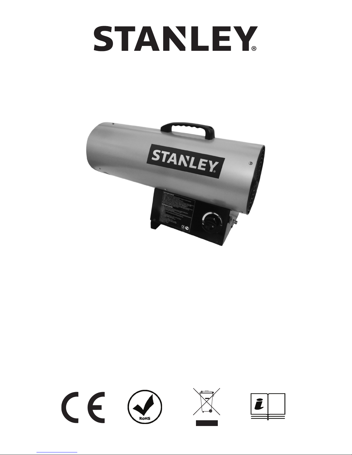
ST-40-GFA-E / ST-60V-GFA-E / ST-100V-GFA-E / ST-150V-GFA-E
— MOBILE GAS FIRED FORCED AIR HEATER —
NEVER LEAVE HEATER UNATTENDED WHILE BURNING, CONNECTED TO A POWER
SOURCE,OR WHILE CONNECTED TO A FUEL SOURCE.
0359
STGA-436
Page 2
© 2017, Obelis S.A Registered Address:
Bd. Général Wahis, 53, 1030 Brussels, Belgium
Read The Instruction manual: When this symbol is marked on a product, it means that the
instruction manual must be read.
This appliance can be used by children aged from 8 years and above and persons with
reduced physical, sensory or mental capabilities or lack of experience and knowledge if they
have been given supervision or instruction concerning use of the appliance in a safe way and
understand the hazards involved. Children shall not play with the appliance. Cleaning and
user maintenance shall not be made by children without supervision.
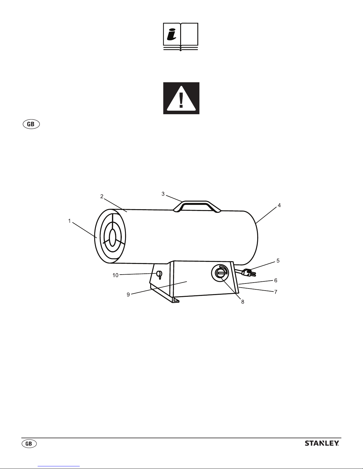
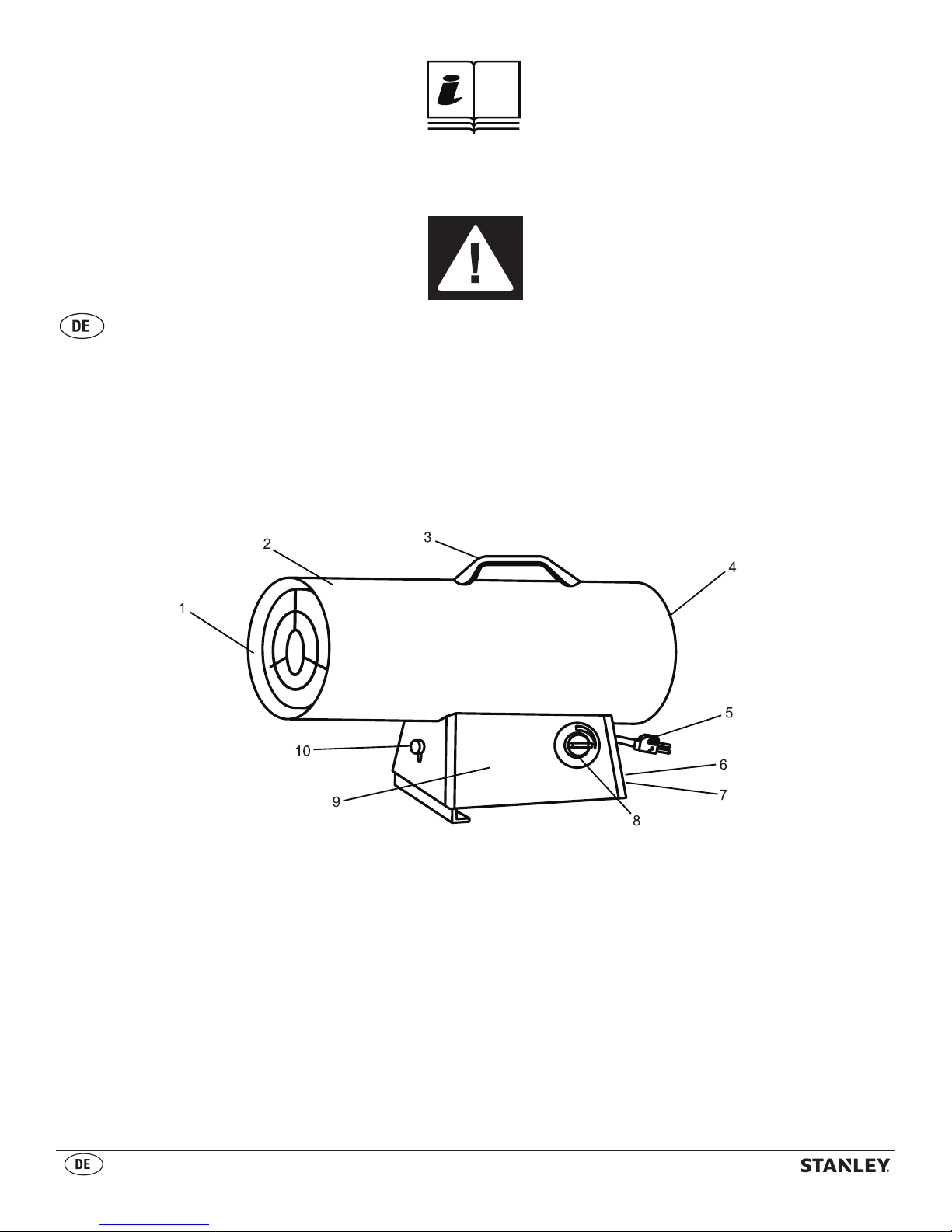
1. INNER SHELL
2. OUTER SHELL
3. HANDLE
4. REAR GUARD
5. POWER CORD
6. POWER SWITCH
7. INLET CONNECTOR
8. VALVE KNOB
9. BASE
10. HEIGHT CONTROLLER
1
Page 3
© 2017, Obelis S.A Registered Address:
Bd. Général Wahis, 53, 1030 Brussels, Belgium
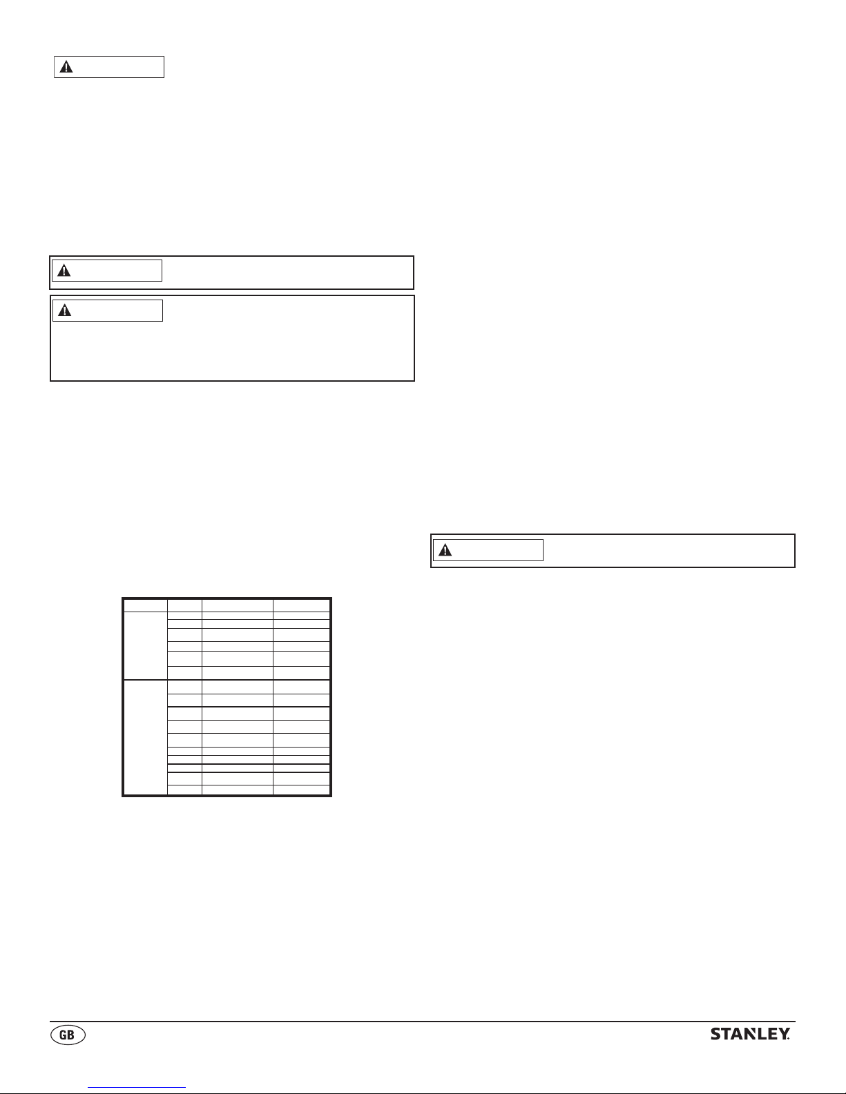
SPECIFICATIONS
Specications subject to change without notice
Model # ST-40-GFA-E ST-60V-GFA-E ST-100V-GFA-E ST-150V-GFA-E
THERMAL POWER (kW) 12.3 11.2-17.5 19.8-28.4 32.5-43.9
THERMAL POWER (GRAMS/HR) 862 770-1200 1451-2041 2359-3039
3
HEATING AREA (m
FUEL CONSUMPTION (Kg/HR) 0.86 0.77-1.2 1.5-2.0 2.4-3.1
MAX OPERATING HOURS 15 16 31 19
VOLTAGE 230V ~ 50Hz 230V ~ 50Hz 230V ~ 50Hz 230V ~ 50Hz
MOTOR PHASE 1Ø 1Ø 1Ø 1Ø
INGRESS PROTECTION RATING 44 44 44 44
AIRFLOW (CMH) 510 510 680 680
APPLIANCE CATEGORY A3 A3 A3 A3
AIR TEMPERATURE CLASS 44°C 44°C 44°C 44°C
) 227 339 566 860
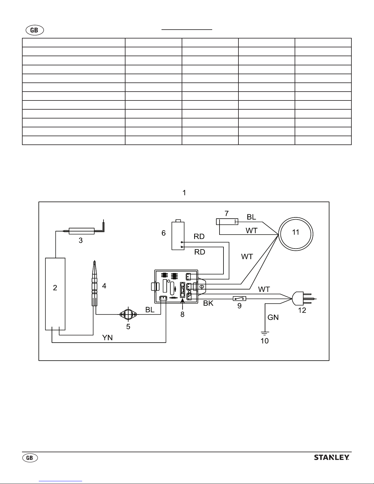
WIRING DIAGRAM
1. PANEL PCB
2. CONTROL VALVE
3. IGNITOR
4. THERMOCOUPLE
5. THERMAL
SWITCH
6. SOLENOID
7. CAPACITOR
8. FUSE
9. OPERATING
SWITCH
10. EARTH
11. MOTOR
12. POWER PLUG
BL. BLUE
RD. RED
2
BK. BLACK
WT. WHITE
GN. GREEN
YN. YELLOW
Page 4
© 2017, Obelis S.A Registered Address:
Bd. Général Wahis, 53, 1030 Brussels, Belgium
Read this User’s Manual carefully and completely before
DANGER
WARNING
WARNING
attempting to operate or service this heater. If the information
in this manual is not followed exactly, a fire or explosion may
result causing property damage, personal injury or loss of life.
- Do not store or use gasoline or other flammable vapors and liquids
in the vicinity of this or any other appliance.
- An LP cylinder not connected for use shall not be stored in the
vicinity of this or any other appliance.
WHAT TO DO IF THE SMELL OF GAS IS PRESENT:
- DO NOT attempt to light heater! Extinguish any open flame
- Shut off the gas supply to the heater.
- If odour continues, contact your local LPG supplier or fire dept.
- Ventilate area thoroughly.
- Do not touch any electric switch, do not use any phone in your
building.
- Immediately call your LPG supplier from a neighbor’s phone.
Follow the LPG supplier instructions.
- If you cannot reach your gas supplier, call the fire department.
- Service must be done by a qualified service agency or the LPG
supplier.
NOT TO BE USED FOR THE HEATING OF HABITABLE AREAS OF
DOMESTIC PREMISES;FOR USE IN PUBLIC BUILDINGS, REFER TO
NATIONAL REGULATIONS
1. Read and understand the instructions and safety warnings
contained in the instruction manual before use. Failure to do
so could result in personal injury or property damage. Failure
to do so will also invalidate the warranty.
2. Only use the heater in well ventilated areas.
3. Ensure the heater is connected to an earthed electrical socket
of the correct voltage.
4. Ensure heater is correctly turned off after use and disconnect
LPG supply cylinder. Only fully qualified personnel should
carry out maintenance and repair.
5. Ensure heater has cooled down before undertaking any
maintenance.
6. DO NOT use heater in areas containing flammable or
explosive material.
7. DO NOT point heater at the LPG supply cylinder.
8. DO NOT obstruct the air inlet and the outlet sections of the
heater.
9. DO NOT operate the heater without the Shell or Cover.
10. DO NOT exceed the 100W / mtr3 limit considering the
volume of the empty operating area.
11. DO NOT use a bare flame to try and ignite the heater.
General Safety Information
WARNING
such as building materials, paper, or cardboard, at a
safe distance away from heater as recommended by the
instructions. Never use the heater in spaces which do or
may contain volatile or airborne com bustibles or products
such as gasoline, diesel, petrol, solvents, paint thinner, dust
particles, or unknown chemicals.
Consumer: Retain these instructions for future reference.
IMPORTANT: Read this User’s Manual carefully and completely
before attempting to operate or service this heater.
fire, explosion, electrical shock and /or carbon monoxide
poisoning. DO NOT use this heater below ground level or in
a basement.
This heater is designed as a construction heater in accordance
with CE Gas Appliance Directive 2009/142/EC, Annex 1 based
on EN 1596: 1998 / A1:2004. Other standards govern the use
of fuel gases and heating products for specific uses. Your local
authority can advise you about these. The primary purpose of
construction heaters is to provide temporary heating of buildings
under construction, alteration, or repair. Properly used, the heater
provides safe economical heating. Products of com bustion are
vented into the area being heated.
Fire, burn, inhalation, and explosion
hazard. Keep solid combustibles
Improper use of this heater can result
in serious injury or death from burns,
Not for home or recreational vehicle use.
The hose assembly shall be pro tected from
traffic, building materials and contact with hot surfaces both
during use and while in storage. Not for use with duct work.
IMPORTANT SAFETY INFORMATION
- Children should be kept away.
- Always maintain proper clearance from combustible materials.
Minimum clearance should be:
Sides -.6 metres Top - .9 metres Front - 3.1 metres
- Heater must be placed on level and solid footing.
- Never place anything, including clothes or other flammable
items on heater.
- Do not modify heater, or operate a heater that has been
modified. Never use with duct work.
- Adequate clearance for accessibility, combustion and ventila-
tion (air supply) must be maintained at all times when heater is
operating. Do not restrict air inlet or outlet areas of heater.
- Do Not use this heater in a basement or below ground level.
- Service and repair should be performed by a qualified service
person. The heater should be inspected before each use, and
at least annually by a qualified person. More frequent cleaning
may be required as necessary. Do not service heater while hot
or operating.
- Never connect heater to an unregulated gas supply.
- To prevent injury, always wear gloves when handling heater.
Never handle an operating or hot heater, as severe burns may
result.
- Use heater in accordance with all local codes.
- Locate LPG supply cylinder at least 1.8 metres from the heater,
and do not direct heater discharge towards the LPG supply cylinder unless it is at least 6 metres from the heater.
- You must check all electrical products, before use, to ensure
that they are safe.
- You must inspect power cables, plugs sockets and any other
connectors for wear or damage.
- You must ensure that the risk of electric shock is minimized by
the installation of appropriate safety devices.
- Ensure that the insulation on all cable and on the appliance is
safe before connecting it to the power supply.
- Ensure that cables are always protected against short circuit
and overload.
- Regularly inspect power supply cable and plugs for wear or
damage and check all connections to ensure that none are
loose.
- Store LP cylinder according to applicable regulations.
- DO NOT pull or carry the appliance by the power cable.
- DO NOT pull the plug from the socket by the cable.
- DO NOT use worn or damaged cable, plugs or connectors.
- Always keep LP cylinder securely fastened and in an upright
position.
Be sure ambient temperature is not less
than -10°C when storing LPG supply
cylinder. Take precautions to avoid accidental heating of
the LPG supply cylinder.
If ice forms on the LPG supply cylinder, DO NOT use the
heater to de-ice the LPG supply cylinder.
UNPACKING
1. Remove all packing items applied to heater for shipment. Keep
plastic cover caps attached to inlet connector and hose/
regulator assembly for storage.
2. Remove all items from carton.
3. Check all items for shipping damage. If heater is damaged,
promptly inform dealer where you purchased the heater.
4. Thoroughly inspect the heater, hose and regulator for signs of
damage. Do not attempt to use any heater that shows signs of
damage.
3
Page 5
© 2017, Obelis S.A Registered Address:
Bd. Général Wahis, 53, 1030 Brussels, Belgium
The Propane (LPG) gas pressure
WARNING
WARNING
regulator and hose assembly supplied
with the heater must be used without alteration.
INSTALLATION
Minimum ventilation requirements: room volume should not
be less than 100 m³; minimum ventilation of 25 cm² per kW of
heat input subject to a minimum of 250 cm².
1. Inspect LPG supply cylinder to ensure it is in good condition.
2. Connect power cord to electrical supply outlet.
3. Connect Gas supply hose to heater. (Required hose and
regulator is to be 1.5 metres max and 1.0 metre min. in
length, and type EN12864). Connect other end (regulator) to
an LPG supply cylinder.
WARNING
CAUTION
Be careful to avoid torsional stresses in
the flexible tubing (regulator hose).
Use the appropriate LPG supply cylinder
listed below.
ST-40-GFA-E : 9 Kg to 45 Kg LPG cylinder
ST-60V-GFA-E : 9 Kg to 45 Kg LPG cylinder
ST-100V-GFA-E : 9 Kg to 45 Kg LPG cylinder
ST-150V-GFA-E : 9 Kg to 45 Kg LPG cylinder
NOTE: Optimum efficiency is achieved when the heater uses
the appropriate full LPG supply cylinder.
4. Slowly open the LPG supply cylinder. Leak test all gas
connections with 50/50 soap and water solution prior to start-up
to ensure the heater is connected properly. Soap bubbles
indicate a gas leak. DO NOT use a match or flame to test for
gas leaks.
NOTE: Consult local regulations when planning to install an
air temperature control.
6. Once burner is lit, push in and turn Valve Knob to desired
setting (1/2/3), (ST-40-GFA-E only has one setting).
SHUTDOWN INSTRUCTIONS
1. Turn gas valve control knob on the heater to the O (OFF)
position.
2. Turn the control knob at the LPG supply cylinder clockwise to
the CLOSED position.
3. Disconnect heater from power supply, and disconnect regulator
from the LPG supply cylinder.
SERVICING INSTRUCTIONS
These instructions are intended to be used only by competent
persons and they shall provide detailed instructions for carrying
out all servicing operations authorized by the manufacturer.
All special tools, materials or servicing aids necessary for the
correct servicing of the appliance shall be specified. Be sure to
check heater for soundness.
- Heater surface temperature must be cold before initiating
service, cleaning or storage.
- Maintenance and repair must be carried out by trained
personnel only at least 2 times per season.
- Before commencing service maintenance disconnect the unit
from the electrical power and the gas supply.
- Check the LPG supply hose condition and change if necessary.
- Check the ignition unit, safety thermostat, and thermocouple
condition and ensure that they are clean. If flame pattern
appears irregular, check nozzle. Wear eye protection when
performing these checks.
- Clean inside the heater unit and the fan blade with compressed
air. Heater is operating correctly when fan is running, flame is
present and soap test showed no leaks.
CHANGING LPG SUPPLY CYLINDERS
1. When changing LPG supply cylinders, be sure this is done in a
flame-free atmosphere.
Model No.
ST-40-GFA-E
ST-60V-GFA-E
ST-100V-GFA-E
ST-150V-GFA-E
Gas
Gas Type and Inlet Pressure
Category
G30 Butane at 37 mbar
I3B/P(37)
I3B/P(37)
G31 Propane at 37 mbar
I3B/P(50)
/ G30
G31 Propane at 30 mbar
I3P(30) / G31
G31 Propane at 37 mbar
I3P(37) / G31
I3P(50) / G31G31 Propane at 50 mbar
I3+(28-30/37)
G30 Butane at 28-30 mbar
G31 Propane at 37 mbar
/ G30
I3+(28-30/37)
G30 Butane at 30 mbar
/ G30
I3+(28-30/37)
G31 Propane at 37 mbar
/ G31
I3B/P(30) /
G30 Butane at 30 mbar
G30
I3B/P(50)
G30 Butane at 50 mbar
/ G30
I3B/P(37)
G30 Butane at 37 mbar
I3B/P(37)
G31 Propane at 37 mbar
I3P(30) / G31
G31 Propane at 30 mbar
I3P(37) / G31G31 Propane at 37 mbar
I3P(50) / G31G31 Propane at 50 mbar
Destination Countries
PL
PL
DE, AT, SK, CHG30 Butane at 50 mbar
NL, RO, TR
BE, FR, IE, PT, GB,
CH, HR, LT, SI, SK
NL, CH, DE, SK
FR, IE, PT, GB, IT
LT, LU & LV, SI, SK
BE
BE
DK, FI, NO, NL, SE, LU, SI
LT, RO, HR, TR, BG, MT, SK
DE, AT, CH, SK
PL
PL, SI
NL, RO, TR
BE, FR, IE, PT, GB,
CH, HR, LT, SI, SK
NL, CH, DE, SK
LIGHTING INSTRUCTIONS
1. Inspect heater before each use. Switch the electrical power
switch to ON and check if fan is operating correctly.
2. Wait five (5) minutes for any gas to clear. Smell for gas. If none
is evident, proceed to the next step.
3. Push in and turn the Valve Knob to the 1 position. This will light
the burner. It may be necessary to repeat this process a few
times to light the heater.
4. Keep the Valve Knob depressed for at least 30 seconds after
the burner is lit. After 30 seconds release the Valve Knob.
5. If burner does not stay lit, wait one minute and repeat Steps 3
and 4.
Disconnect heater from LPG supply
cylinder when not in use.
LONG TERM STORAGE
Always disconnect the heater from the LPG supply cylinder
before putting the heater into storage. If for any reason the heater
is to be stored indoors, the heater MUST be disconnected from
the LPG supply cylinder, and the cylinder stored outdoors in a
well-ventilated area, and out of the reach of children.
The plastic valve plug or valve cover supplied with the LPG
supply cylinder must be re-installed on the valve to protect the
fitting from damage.
This appliance is not intended for use by
persons (including children) with reduced
physical, sensory or mental capabilities,
or lack of experience and knowledge,
unless they have been given supervision or
instruction concerning use of the appliance
by a person responsible for their safety.
Children should be supervised to ensure that
they do not play with the appliance.
If the power cord is damaged, it must be
replaced by the manufacturer, its service
agent or similarly qualified persons in order
to avoid a hazard.
- NOTE: In some countries, there may be differences
in the requirements listed in this manual. In these
cases, contact your local dealer for possible
variations from requirements in this manual.
4
Page 6
© 2017, Obelis S.A Registered Address:
Bd. Général Wahis, 53, 1030 Brussels, Belgium
WARNING
Plug Replacement
WARNING
RISK OF ELECTRIC SHOCK! DISCONNECT FROM POWER BEFORE MAINTENANCE.
NOTE: This section only applies to heaters sold or used in Great Britain.
This appliance is supplied with a BS1363 3 pin
plug tted with a fuse. Should the fuse require
replacement, it must be replaced with a fuse with the
proper amp rating. (see Technical Specications page
2) and approved to BS1362.
In the event the mains plug has to be removed/
replaced for any reason, please note:
IMPORTANT: The wires in the mains lead are colored
in accordance with the following code:
Blue – Neutral Brown – Live
Green/Yellow – Earth
As the colors of the wires in the mains lead of this
appliance may not correspond with the colored
markings identifying the terminals in your plug,
proceed as follows:
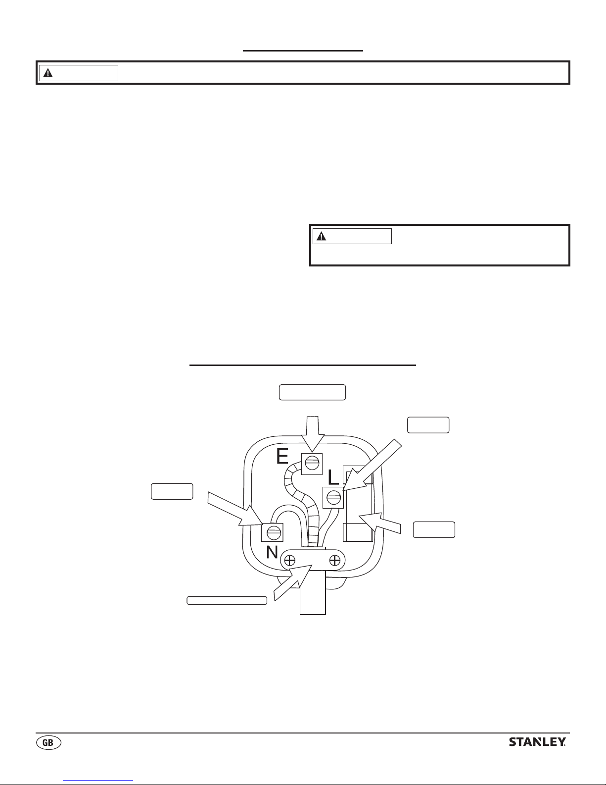
Plug Replacement Wiring Diagram
GREEN / YELLOW
The blue wire must be connected to the terminal
marked with an N or colored black. The brown wire
must be connected to the terminal marked with an
L or colored red. The green/ yellow wire must be
connected to the earthing terminal which is marked
with an E or with the earth symbol.
Never connect live or neutral
wires to the earth terminal of
the plug.
NOTE: If a moulded plug is tted and has to be
removed take great care in disposing of the plug
and severed cable, it must be destroyed to prevent
engaging into a socket.
Earth
BLUE
Neutral
CORD CLAMP
BROWN
Live
FUSE
3 Amps
5
Page 7

© 2017, Obelis S.A Registered Address:
Bd. Général Wahis, 53, 1030 Brussels, Belgium
TROUBLESHOOTING GUIDE
Problem
Fan does not turn when electricity is
connected.
Heater will not fire (ignite).
Heater stops running by itself.
Possible Cause Solution
1. No electric power to heater.
2. Blades of fan in contact with heater
housing.
3. Fan blades bent.
4. Fan motor defective.
1. No spark at module.
2. Incorrect spark gap.
3. Corroded electrode.
1. Temperature inside heater is too
high, causing thermal switch to shut
down operation.
2. Damaged control valve.
3. Dust or debris accumulated in
heater.
1. Check current at outlet. If voltage
is correct, inspect extension and
power cords for cuts, frays or
breaks.
2. Check housing for damage. Be sure
there are no dents in the housing
obstructing the fan.
3. Straighten all fan blades.
4. Replace Motor Assembly.
1. Inspect module wire. Re-attach,
or tighten if loose. Inspect Spark
module, and replace if necessary.
Inspect all other electrical
components.
2. Set plug gap to 0.16” (4mm).
3. Replace spark plug
(Multi-Bracket Assembly).
1. If heater input or output is restricted,
the inside temperature can become
too hot. Keep the areas in front and
behind heater clear of obstructions.
2. Replace control valve
(Valve Assembly).
3. Clean inside of heater.
STANLEY, The STANLEY Logo, The Notched Rectangle and the Yellow and Black Diagonal Package
Design are all trademarks of Stanley Black & Decker, Inc. or an affiliate thereof.
6
Page 8
© 2017, Obelis S.A Registered Address:
Bd. Général Wahis, 53, 1030 Brussels, Belgium
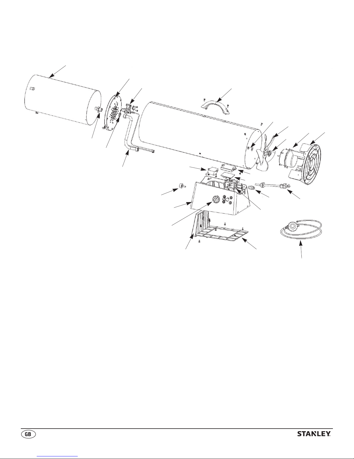
EXPLODED VIEW
1
5
6
8
9
10
11
12
13
14
15
7
21
20
19
16
2
17
18
23
22
3
4
24
7
Page 9

© 2017, Obelis S.A Registered Address:
Bd. Général Wahis, 53, 1030 Brussels, Belgium
PARTS LIST
# ST-40-GFA-E / ST-60V-GFA-E / ST-100V-GFA-E / ST-150V-GFA-E
1 Inner Shell / Combustion Chamber
2 Base
3 Height Controller
4 Base Cover
5 Inner Shell Cap
6 Multi bracket
7 Tubing
8 Nozzle
9 Nozzle Nut
10 Handle
11 Flange Hex Nut
12 Fan Blade
13 Cushion Pad
14 Motor
15 Rear Guard
16 Round Bolt
17 Valve Assembly
18 Inlet Connector
19 Spark Module
20 PCB
21 PCB Case
22 Control Knob
23 Power Cord
24 Regulator and hose
8
Page 10

Bd. Général Wahis, 53, 1030 Brussels, Belgium
Obelis S.A Registered Address:
© 2017 Stanley Black & Decker, Inc.
Page 11
ST-40-GFA-E / ST-60V-GFA-E / ST-100V-GFA-E / ST-150V-GFA-E
— MOBILES GASHEIZGEBLÄSE —
DAS BRENNENDE, MIT EINER STROMQUELLE ODER BRENNSTOFFQUELLE
VERBUNDENE HEIZGERÄT NIEMALS UNBEAUFSICHTIGT LASSEN.
0359
Page 12
© 2017, Obelis S.A Registered Address:
Bd.Général Wahis, 53, 1030 Brussels, Belgium
Betriebsanleitung lesen: Wenn ein Produkt mit diesem Symbol gekennzeichnet ist,
muss die Betriebsanleitung gelesen werden.
Dieses Gerät darf nicht von Personen (einschließlich Kindern) mit
eingeschränkten körperlichen, sensorischen oder geistigen Fähigkeiten und
nicht von Personen mit mangelnder Erfahrung und mangelnden Kenntnissen
verwendet werden, außer wenn diese beaufsichtigt werden oder von einer für
ihre Sicherheit verantwortlichen Person entsprechend in den sicheren Betrieb
des Geräts eingewiesen wurden. Kinder müssen beaufsichtigt werden, um
sicherzustellen, dass sie nicht mit dem Gerät spielen.
1. INNENGEHÄUSE
2. AUSSENGEHÄUSE
3. HALTEGRIFF
4. HINTERES SCHUTZGITTER
5. NETZKABEL
6. NETZSCHALTER
7. ANSAUGANSCHLUSS
8. VENTILKNOPF
9. SOCKEL
10. HÖHENREGLER
1
Page 13

© 2017, Obelis S.A Registered Address:
Bd.Général Wahis, 53, 1030 Brussels, Belgium
TECHNISCHE DATEN
Änderungen vorbehalten
Modellnr ST-40-GFA-E ST-60V-GFA-E ST-100V-GFA-E ST-150V-GFA-E
WÄRMELEISTUNG (kW) 12,3 11,2-17,5 19,8-28,4 32.5-43.9
WÄRMELEISTUNG (g/h) 862 770-1200 1451-2041 2359-3039
3
HEIZFLÄCHE (m
BRENNSTOFFVERBRAUCH (Kg/h) 0,86 0,77-1,2 1,5-2,0 2.4-3.1
MAX. BETRIEBSDAUER IN STUNDEN 15 16 31 19
SPANNUNG 230V ~ 50Hz 230V ~ 50Hz 230V ~ 50Hz 230V ~ 50Hz
MOTORPHASE 1Ø 1Ø 1Ø 1Ø
IP WERTUNG 44 44 44 44
LUFTDURCHSATZ (CMH) 510 510 680 680
GERÄTEKLASSE A3 A3 A3 A3
LUFTTEMPERATURKLASSE 44°C 44°C 44°C 44°C
) 227 339 566 860
SCHALTPLAN
1. BEDIENFELD-LEITERPLATTE
2. STEUERENTIL
3. ZÜNDER
4. THERMOELEMENT
5. WÄRMESCHUTZSCHALTER
6. MAGNETSPULE
7. KONDENSATOR
8. SICHERUNG
9. BETRIEBSSCHALTER
10. MASSE
11. MOTOR
12. NETZSTECKER
BL. BLAU
RD. ROT
BK. SCHWARZ
WT. WEISS
GN. GRÜN
YN. GELB
2
Page 14

© 2017, Obelis S.A Registered Address:
Bd.Général Wahis, 53, 1030 Brussels, Belgium
Dieses Benutzerhandbuch muss vor der Inbetriebnahme oder Wartung
GEFAHR
des Heizgeräts sorgfältig und vollständig durchgelesen werden. Wenn
die in dieser Anleitung aufgeführten Anweisungen nicht genau befolgt
werden, besteht Brand- oder Explosionsgefahr, die zu Sachschäden und
schweren oder tödlichen Verletzungen führen kann.
- Benzin und andere brennbare Gase oder Flüssigkeiten dürfen nicht in der
Nähe dieses oder eines anderen Geräts gelagert oder verwendet werden.
- Nicht zur Verwendung angeschlossene Flüssiggasflaschen dürfen nicht in
der Nähe dieses oder eines anderen Geräts gelagert werden.
VORGEHENSWEISE BEI GASGERUCHSENTWICKLUNG:
- NICHT versuchen, das Heizgerät zu zünden! Jegliche offenen
Flammen löschen.
- Die Gaszufuhr zum Heizgerät schließen.
- Falls der Geruch bestehen bleibt, den örtlichen Flüssiggaslieferanten oder
die Feuerwehr kontaktieren.
- Den Bereich gut lüften.
- Keine elektrischen Schalter berühren und im Gebäude kein Telefon benutzen.
- Umgehend vom Telefon eines Nachbarn aus den Flüssiggaslieferanten
anrufen. Die Anweisungen des Flüssiggaslieferanten befolgen.
- Falls der Gaslieferant nicht erreichbar ist, die Feuerwehr anrufen.
- Die Wartung muss von einem qualifizierten Wartungsunternehmen oder vom
Flüssiggaslieferanten durchgeführt werden.
NICHT ZUM HEIZEN VON WOHNRÄUMEN IN PRIVATHAUSHALTEN
BESTIMMT; BEI VERWENDUNG IN ÖFFENTLICHEN GEBÄUDEN
SIND DIE NATIONALEN VORSCHRIFTEN ZU BEACHTEN.
1. Vor der Verwendung müssen die in dieser Betriebsanleitung aufgeführten
Anweisungen und Sicherheitshinweise gelesen und verstanden werden.
Bei Nichtbeachtung sind Verletzungen und Sachschäden möglich.
Darüber hinaus führt die Nichtbeachtung zum Erlöschen der Garantie.
2. Das Heizgerät nur in gut belüfteten Bereichen verwenden.
3. Sicherstellen, dass das Heizgerät an einer Schukosteckdose eingesteckt
wird, an der die richtige Spannung anliegt.
4. Sicherstellen, dass das Heizgerät nach der Verwendung ordnungsgemäß
ausgeschaltet und die Flüssiggasflasche abgeklemmt wird.
Wartungs- und Reparaturarbeiten dürfen nur von qualifiziertem
Personal durchgeführt werden.
5. Das Heizgerät vor der Wartung abkühlen lassen.
6. Das Heizgerät NICHT in Bereichen mit brennbarem oder explosivem
Material betreiben.
7. Das Heizgerät NICHT auf die Flüssiggasflasche richten.
8. Die Luftein- und Luftauslässe des Heizgeräts NICHT blockieren.
9. Das Heizgerät NICHT ohne Gehäuse oder Schutzabdeckung betreiben.
10. Unter Berücksichtigung des Volumens des leeren Betriebsbereichs
darf die 100 W/m3-Grenze NICHT überschritten werden.
11. Zum Zünden des Heizgeräts KEINE offene Flamme verwenden.
Allgemeine Sicherheitshinweise
Brand-, Verbrennungs-, Einatmungs- und
Explosionsgefahr. Darauf achten, dass sich
feste Brennstoffe, wie Baustoffe, Papier oder Pappe, anweisungsgemäß
in sicherem Abstand zum Heizgerät befinden. Das Heizgerät niemals
in Räumen, die flüchtige oder luftgetragene Brennstoffe oder Produkte
wie Benzin, Diesel, Lösungsmittel, Farbverdünner, Staubpartikel oder
unbekannte Chemikalien enthalten bzw. enthalten könnten, verwenden.
Hinweis für den Endkunden: Bewahren Sie diese Anweisungen zur
künftigen Bezugnahme sorgfältig auf.
WICHTIG: Dieses Benutzerhandbuch muss vor der Inbetriebnahme oder
Wartung des Heizgeräts sorgfältig und vollständig durchgelesen werden.
Die unsachgemäße Verwendung dieses
Heizgeräts kann zu schweren oder tödlichen
Verletzungen durch Verbrennungen, Feuer, Explosion, Elektroschock
und/oder Kohlenmonoxidvergiftung führen. Das Heizgerät NICHT unter
der Erde oder im Keller verwenden.
Dieses Heizgerät wurde gemäß der CE-Richtlinie über
Gasverbrauchseinrichtungen 2009/142/EG, Anhang 1 auf Basis der Norm
EN 1596: 1998 / 2004 als Bauheizgerät konzipiert. Andere Normen können
weitere Regelungen bezüglich der Verwendung von Brenngasen und
Heizprodukten für bestimmte Zwecke beinhalten. Einzelheiten hierzu erhalten
Sie bei Ihrer örtlichen Behörde. Die Hauptaufgabe von Bauheizgeräten
besteht darin, Gebäude während der Bauphase oder während Umbau- oder
Reparaturmaßnahmen vorübergehend zu heizen. Bei ordnungsgemäßer
Verwendung bietet dieses Heizgerät eine sichere und wirtschaftliche
Heizlösung. Entstehende Verbrennungsprodukte werden in den zu heizenden
Bereich abgeleitet.
Nicht zur Verwendung in Wohnhäusern oder
Wohnmobilen bestimmt. Die Schlauchbaugruppe
muss während des Betriebs und während der Lagerung vor Verkehr,
Baumaterialien und Kontakt mit heißen Oberflächen geschützt werden.
Nicht zur Verwendung mit Luftkanälen bestimmt.
WICHTIGE SICHERHEITSHINWEISE
- Kinder fernhalten.
- Stets ausreichend Abstand zu brennbaren Materialien einhalten. Richtwerte
für den Mindestabstand:
Seitlich- 0,6 Meter Oben- 0,9 Meter Vorne- 3,1 Meter
- Das Heizgerät muss auf einer ebenen und stabilen Fläche
aufgestellt werden.
- Niemals brennbare Gegenstände, wie z. B. Kleidung, auf das
Heizgerät legen.
- Das Heizgerät nicht modifizieren. Modifizierte Heizgeräte dürfen nicht
verwendet werden. Niemals zusammen mit Luftkanälen verwenden.
- Während des Betriebs des Heizgeräts stets für ausreichend Abstand für
Zugänglichkeit, Verbrennung und Belüftung (Luftzufuhr) sorgen.
Die Luftein-und Luftauslässe des Heizgeräts nicht blockieren.
- Das Heizgerät nicht im Keller oder unter der Erde verwenden.
- Wartungs-und Reparaturarbeiten müssen von einem qualifizierten
Servicetechniker durchgeführt werden. Das Heizgerät muss vor jeder
Verwendung inspiziert und mindestens einmal jährlich von einer
qualifizierten Person überprüft werden. Gegebenenfalls ist eine häufigere
Reinigung erforderlich. Das Heizgerät niemals in heißem Zustand oder
während des Betriebs warten.
- Das Heizgerät niemals an eine ungeregelte Gasquelle anschließen.
- Zur Vermeidung von Verletzungen sind bei Arbeiten mit dem Heizgerät stets
Handschuhe zu tragen. Niemals ein in Betrieb befindliches oder heißes
Gerät handhaben, da Verbrennungsgefahr besteht.
- Das Heizgerät unter Beachtung aller lokalen Gesetze verwenden.
- Die Flüssiggasflasche mindestens 1,8 Meter vom Heizgerät entfernt
positionieren und den Luftstrom nicht auf die Flüssiggasflasche richten,
sofern deren Abstand zum Heizgerät nicht mindestens 6 Meter beträgt.
- Vor der Verwendung müssen alle elektrischen Geräte überprüft werden, um
sicherzustellen, dass diese sicher betrieben werden können.
- Netzkabel, Stecker, Steckdosen und andere Verbindungen auf Verschleiß
und Schäden überprüfen.
- Durch die Installation von Schutzvorrichtungen sicherstellen, dass das Risiko
eines Stromschlags minimal gehalten wird.
- Vor dem Anschließen an die Stromversorgung sicherstellen, dass die
Isolierung an allen Kabeln und am Gerät intakt ist.
- Sicherstellen, dass alle Kabel stets vor Kurzschluss und Überlastung
geschützt sind.
- Das Netzkabel und die Stecker regelmäßig auf Verschleiß und Schäden
überprüfen und den festen Sitz aller Verbindungen bestätigen.
- Die Flüssiggasflasche gemäß den geltenden Bestimmungen lagern.
- Das Gerät NICHT am Netzkabel ziehen oder tragen.
- Den Stecker NICHT am Kabel aus der Steckdose ziehen.
- KEINE verschlissenen oder beschädigten Kabel, Stecker oder
Anschlüsse verwenden.
- Die Flüssiggasflasche muss stets sicher befestigt und aufrecht
positioniert sein.
Sicherstellen, dass die Flüssiggasflasche nicht
bei Umgebungstemperaturen von unter -10 °C
gelagert wird. Entsprechende Vorkehrungen
treffen, damit die Flüssiggasflasche nicht versehentlich erhitzt wird.
Bei Eisbildung auf der Flüssiggasflasche diese NICHT mithilfe des
Heizgeräts enteisen.
AUSPACKEN
1. Alle Transportschutzverpackungen vom Heizgerät entfernen. Die am
Ansauganschluss und an der Schlauch/Regler-Baugruppe angebrachten
Kunststoff-Abdeckkappen während der Lagerung nicht entfernen.
2. Alle Teile aus dem Karton nehmen.
3. Alle Teile auf Transportschäden überprüfen. Bei Schäden am Heizgerät
umgehend den Händler kontaktieren, bei dem das Heizgerät gekauft wurde.
4. Das Heizgerät, den Schlauch und den Regler gründlich auf Verschleiß und
Schäden überprüfen. Niemals ein Heizgerät verwenden, das Anzeichen von
Schäden aufweist.
3
Page 15

© 2017, Obelis S.A Registered Address:
Bd.Général Wahis, 53, 1030 Brussels, Belgium
Die im Lieferumfang des Heizgeräts
VORSICHT
I3B/P(50)
/ G30
Bestimmungsland
Gasart und Versorgungsdruck
Gas-
kbeiegorie
Modell
ST-60V-GFA-E
ST-100V-GFA-E
ST-150V-GFA-E
I3+(28-30/37)
/ G30
I3B/P(30) /
G30
I3P(30) / G31
G30 Butan bei 28-30 mbar
G31 Propan bei 37 mbar
FR, IE, PT, GB, IT
LT, LU & LV, SI, SK
DE, BEI, CH, SK
NL, RO, TR
DK, FI, NO, NL, SE, LU, SI
LT, RO, HR, TR, BG, MT, SK
G30 Butan bei 30 mbar
G31 Propan bei 37 mbar
I3+(28-30/37)
/ G30
BE
I3+(28-30/37)
/ G31
BE
G30 Butan bei 30 mbar
G30 Butan bei 50 mbar
I3B/P(37)
G30 Butan bei 37 mbar
PL
I3B/P(37)
G31 Propan bei 37 mbar
PL, SI
G31 Propan bei 30 mbar
I3P(37) / G31G31 Propan bei 37 mbar
BE, FR, IE, PT, GB,
CH, HR, LT, SI, SK
I3P(50) / G31G31 Propan bei 50 mbar
NL, CH, DE, SK
ST-40-GFA-E
I3B/P(37)
G30 Butan bei 37 mbar
PL
I3B/P(37)
G31 Propan bei 37 mbar
PL
I3B/P(50)
/ G30
DE, BEI, SK, CHG30 Butan bei 50 mbar
I3P(30) / G31
NL, RO, TR
G31 Propan bei 30 mbar
I3P(37) / G31
G31 Propan bei 37 mbar
BE, FR, IE, PT, GB,
CH, HR, LT, SI, SK
I3P(50) / G31G31 Propan bei 50 mbar
NL, CH, DE, SK
enthaltene Propangasdruckregler/Schlauch-
Baugruppe darf nicht verändert werden.
INSTALLATION
Mindestanforderungen für die Belüftung: Das Raumvolumen darf
nicht unter 100 m³ betragen; pro kW Wärmeleistung muss eine Mindestbelüftung von 25 cm², mindestens jedoch 250 cm² gewährleistet
werden.
1. Prüfen, ob die Flüssiggasflasche in gutem Zustand ist.
2. Das Netzkabel in eine Steckdose stecken.
3. Den Gaszufuhrschlauch am Heizgerät anschließen. (Es wird ein
Schlauch und Regler vom Typ EN12864 mit einer Mindestlänge
von 1,0 m und einer Maximallänge von 1,5 m benötigt.) Das andere
Ende (den Regler) an der Flüssiggasflasche anschließen.
4. Den Ventilknopf nach dem Zünden des Brenners mindestens 30
Sekunden lang gedrückt halten und anschließend freigeben.
5. Falls der Brenner erlischt, eine Minute warten und dann die Schritte 3
und 4 wiederholen.
6. Nach dem Zünden des Brenners den Ventilknopf auf die gewünschte
Position (1/2/3) drehen.
ANWEISUNGEN ZUR ABSCHALTUNG
1. Den Regelknopf am Gasventil des Heizgeräts auf die Position „O“
(AUS) drehen.
2. Den Regelknopf an der Flüssiggasflasche nach rechts in die
geschlossene Position (CLOSED) drehen.
3. Das Heizgerät vom Stromnetz und den Regler von der
Flüssiggasflasche trennen.
Darauf achten, dass die flexible
Schlauchleitung (Reglerschlauch) keinen
Torsionsspannungen ausgesetzt wird.
Eine geeignete Flüssiggasflasche verwenden
(siehe nachfolgende Liste).
ST-40-GFA-E: Flüssiggasflasche mit 9 bis 45 kg
ST-60V-GFA-E: Flüssiggasflasche mit 9 bis 45 kg
ST-100V-GFA-E: Flüssiggasflasche mit 9 bis 45 kg
ST-150V-GFA-E: Flüssiggasflasche mit 9 bis 45 kg
HINWEIS: Optimale Effizienz wird bei Verwendung einer geeigneten,
vollen Flüssiggasflasche erzielt.
4. Die Flüssiggasflasche langsam aufdrehen. Vor der Inbetriebnahme
mit einer Lösung aus Seife und Wasser im Verhältnis 50:50 prüfen, ob
alle Gasanschlüsse dicht sind, um sicherzustellen, dass das Heizgerät
ordnungsgemäß angeschlossen wurde. Seifenblasen weisen auf ein
Gasleck hin. NICHT mit Streichhölzern oder Flammen auf Gaslecks
prüfen.
HINWEIS: Wenn ein Lufttemperaturregler installiert werden soll,
müssen die örtlichen Bestimmungen befolgt werden.
WECHSELN DER FLÜSSIGGASFLASCHE
1. Flüssiggasflaschen dürfen nur in flammenfreien Umgebungen
gewechselt werden.
ANWEISUNGEN ZUR WARTUNG
Diese Anleitung darf nur von sachkundigen Personen verwendet werden;
sie enthält detaillierte Anweisungen für alle vom Hersteller genehmigten
Wartungsarbeiten.
Darüber hinaus werden alle Spezialwerkzeuge, Materialien und
Wartungshilfen spezifiziert, die für die ordnungsgemäße Wartung
des Geräts benötigt werden. Den einwandfreien Zustand des Geräts
sicherstellen.
- Vor der Wartung, Reinigung oder Lagerung des Heizgeräts müssen alle
Geräteoberflächen abgekühlt sein.
- Sämtliche Wartungs-und Reinigungsarbeiten müssen mindestens
zweimal pro Saison von geschultem Personal durchgeführt werden.
- Vor der Durchführung von Wartungsarbeiten muss das Gerät vom
Stromnetz und von der Gaszufuhr getrennt werden.
- Den Zustand des Gasflaschenschlauchs überprüfen und diesen bei
Bedarf ersetzen.
- Den Zustand und die Sauberkeit der Zündeinheit, des
Sicherheitsthermostats und des Thermoelements prüfen. Bei
unregelmäßigem Flammenmuster die Düse überprüfen. Bei diesen
Prüfungen muss eine Schutzbrille getragen werden.
- Die Innenflächen des Heizgeräts und die Lüfterflügel mit Druckluft
reinigen. Wenn das Gebläse läuft, eine Flamme sichtbar ist und
mittels Seifenlaugenprüfung keine Leckstellen gefunden werden,
funktioniert das Heizgerät ordnungsgemäß.
Das Heizgerät bei Nichtgebrauch von der
Flüssiggasflasche trennen.
LANGZEITLAGERUNG
Das Heizgerät muss vor der Einlagerung immer von der
Flüssiggasflasche getrennt werden. Falls das Heizgerät aus irgendeinem
Grund innerhalb eines Gebäudes gelagert werden soll, MUSS es von
der Flüssiggasflasche getrennt und die Flüssiggasflasche im Freien
in einem gut belüfteten Bereich und außerhalb der Reichweite von
Kindern aufbewahrt werden. Die im Lieferumfang der Flüssiggasflasche
enthaltene Kunststoffventilschraube bzw. Ventilabdeckung muss wieder
auf dem Ventil angebracht werden, um die Verschraubung vor Schäden
zu schützen.
ANWEISUNGEN ZUM ZÜNDEN
1. Das Heizgerät vor der Verwendung überprüfen.
Den Netzschalter einschalten (ON) und prüfen, ob das Gebläse
ordnungsgemäß funktioniert.
2. Fünf (5) Minuten warten, damit Gasreste entweichen können.
Überprüfen Sie, ob es nach Gas riecht. Wenn kein Gasgeruch
vorhanden ist, gehen Sie zum nächsten Schritt über.
3. Den Ventilknopf drücken und auf Position 1 drehen. Dadurch wird
der Brenner gezündet. Dieser Schritt muss möglicherweise mehrmals
wiederholt werden, um das Heizgerät zu zünden.
Dieses Gerät darf nicht von Personen (einschließlich Kindern)
mit eingeschränkten körperlichen, sensorischen oder geistigen
Fähigkeiten und nicht von Personen mit mangelnder Erfahrung
und mangelnden Kenntnissen verwendet werden, außer wenn
diese beaufsichtigt werden oder von einer für ihre Sicherheit
verantwortlichen Person entsprechend in den sicheren Betrieb des
Geräts eingewiesen wurden. Kinder müssen beaufsichtigt werden,
um sicherzustellen, dass sie nicht mit dem Gerät spielen.
Ein beschädigtes Netzkabel muss vom Hersteller, einem
Kundendienstvertreter oder einer ähnlich qualifizierten Personen
ersetzt werden, um Gefahren zu vermeiden.
HINWEIS: In manchen Ländern können Vorschriften bestehen, die
von den Angaben in dieser Anleitung abweichen. Wenden Sie sich
an Ihren lokalen Händler, um nähere Informationen über mögliche
Abweichungen von den Angaben in dieser Anleitung zu erfahren.
4
Page 16

© 2017, Obelis S.A Registered Address:
Bd.Général Wahis, 53, 1030 Brussels, Belgium
LEITFADEN ZUR FEHLERBEHEBUNG
Problem
Lüfter dreht sich nicht bei Anschluss
an die Stromversorgung.
Heizgerät zündet nicht.
Mögliche Ursache Lösung
1. Keine Stromzufuhr zum Heizgerät.
2. Lüfterflügel berühren das Gehäuse
des Heizgeräts.
3. Verbogene Lüfterflügel.
4. Defekter Lüftermotor.
1. Kein Funken am Modul.
2. Falsche Funkenstrecke.
3. Korrodierte Elektrode.
1. Stromeingang an der Steckdose
überprüfen. Wenn die richtige
Spannung anliegt, Verlängerungsund Netzkabel auf Risse,
Ausfransungen und Brüche
überprüfen.
2. Gehäuse auf Schäden überprüfen.
Sicherstellen, dass das Gehäuse
keine Dellen aufweist, die den
Lüfter blockieren.
3. Alle Lüfterflügel begradigen.
4. Motorbaugruppe ersetzen.
1. Modulverdrahtung überprüfen und
bei Bedarf neu anschließen oder
festziehen. Zündmodul überprüfen
und bei Bedarf reinigen. Alle
anderen elektrischen Komponenten
überprüfen.
2. Den Zündkerzenabstand auf 4 mm
einstellen.
3. Zündkerze ersetzen
(Multi-Halterung).
Heizgerät stoppt den Betrieb.
1. Die Temperatur im Heizgerät ist zu
hoch, weshalb der Betrieb über den
Wärmeschutzschalter gestoppt wird.
2. Beschädigtes Regelventil.
3. Staub- oder Schmutzablagerungen
im Heizgerät.
1. Blockierte Ein- oder Auslässe am
Heizgerät können zu zu hohen
Temperaturen im Geräteinneren
führen. Die Bereiche vor und hinter
dem Heizgerät nicht blockieren.
2. Regelventil (Ventilbaugruppe)
ersetzen.
3. Innenflächen des Heizgeräts
reinigen.
STANLEY, das STANLEY-Logo, das eingekerbte Rechteck sowie das gelb-schwarze
Paketdesign sind Markenzeichen von Stanley Black & Decker, Inc. oder ihrer
Tochterunternehmen.
6
Page 17

© 2017, Obelis S.A Registered Address:
Bd.Général Wahis, 53, 1030 Brussels, Belgium
EXPLOSIONSZEICHNUNG
1
5
6
8
9
10
11
12
13
14
15
7
21
20
19
16
2
17
18
23
22
3
4
24
7
Page 18

© 2017, Obelis S.A Registered Address:
Bd.Général Wahis, 53, 1030 Brussels, Belgium
TEILELISTE
# ST-40-GFA-E / ST-60V-GFA-E / ST-100V-GFA-E / ST-150V-GFA-E
1 Innengehäuse / Brennkammer
2 Sockel
3 Höhenregler
4 Sockelabdeckung
5 Innengehäuse-Kappe
6 Multi-Halterung
7 Schlauch
8 Düse
9 Düsenmutter
10 Haltegriff
11 Sechskant-Flanschmutter
12 Lüfterügel
13 Polsterung
14 Motor
15 Hinteres Schutzgitter
16 Runde Schraube
17 Ventilbaugruppe
18 Ansauganschluss
19 Zündmodul
20 Leiterplatte
21 Leiterplattengehäuse
22 Regelknopf
23 Netzkabel
24 Regler und Schlauch
8
Page 19

Obelis S.A
Registered Address:
Bd. Général Wahis, 53
1030 Brüssel, Belgium
© 2017 Stanley Black & Decker, Inc.
Page 20

ST-40-GFA-E / ST-60V-GFA-E / ST-100V-GFA-E / ST-150V-GFA-E
— STUFA AD ARIA FORZATA PORTATILE A GAS —
NON LASCIARE MAI INCUSTODITO L’APPARECCHIO QUANDO È IN FUNZIONE O QUANDO È
COLLEGATO A UNA FONTE DI COMBUSTIBILE O DI ALIMENTAZIONE.
0359
Page 21

© 2017, Obelis S.A Registered Address:
Bd. Général Wahis, 53, 1030 Brussels, Belgium
IT
Leggere il manuale di istruzioni. Quando questo simbolo appare su un prodotto, significa che
è necessario leggere il manuale di istruzioni.
I bambini di età superiore agli 8 anni e le persone con ridotte capacità siche, sensoriali o
IT
mentali, oppure sprovviste dell’esperienza o delle competenze necessarie, possono usare il
presente apparecchio solo sotto supervisione o dopo aver ricevuto istruzioni circa l’uso sicuro
dell’apparecchio e i pericoli connessi. I bambini non devono giocare con l’apparecchio. La
pulizia e la manutenzione di competenza dell’utente non devono essere eseguite da bambini
senza la supervisione di un adulto.
1. ALLOGGIAMENTO INTERNO
2. ALLOGGIAMENTO ESTERNO
3. MANIGLIA
4. PROTEZIONE POSTERIORE
5. CAVO DI ALIMENTAZIONE
6. INTERRUTTORE DI ACCENSIONE
7. CONNETTORE DI INGRESSO
8. MANOPOLA DELLA VALVOLA
9. BASE
10. REGOLAZIONE DELL’ALTEZZA
1
Page 22

© 2017, Obelis S.A Registered Address:
Bd. Général Wahis, 53, 1030 Brussels, Belgium
IT
IT
N. modello ST-40-GFA-E ST-60V-GFA-E ST-100V-GFA-E ST-150V-GFA-E
POTENZA TERMICA (kW) 12,3 11,2-17,5 19,8-28,4 32,5-43,9
CONSUMO (g/h) 862 770-1200 1451-2041 2359-3039
3
AREA RISCALDATA (m
ORE DI FUNZIONAMENTO MAX 15 16 31 19
TENSIONE 230 V~, 50 Hz 230 V~, 50 Hz 230 V~, 50 Hz 230 V~, 50 Hz
TIPO DI MOTORE 1Ø 1Ø 1Ø 1Ø
CLASSE DI PROTEZIONE IP 44 44 44 44
FLUSSO D’ARIA (m³/h) 510 510 680 680
CATEGORIA DELL’APPARECCHIO A3 A3 A3 A3
CLASSE DI TEMPERATURA DELL’ARIA 44 °C 44 °C 44 °C 44 °C
) 227 339 566 860
Speciche soggette a modiche senza preavviso
SPECIFICHE
SCHEMA ELETTRICO
1. SCHEDA DI CIRCUITO
DEL PANNELLO
2. VALVOLA DI CONTROLLO
3. ACCENDITORE
4. TERMOCOPPIA
5. INTERRUTTORE TERMICO
6. SOLENOIDE
7. CONDENSATORE
8. FUSIBILE
9. INTERRUTTORE DI
ACCENSIONE
10. TERRA
11. MOTORE
12. SPINA
BL. BLU
RD. ROSSO
2
BK. NERO
WT. BIANCO
GN. VERDE
YN. GIALLO
Page 23

© 2017, Obelis S.A Registered Address:
Bd. Général Wahis, 53, 1030 Brussels, Belgium
IT
Leggere con attenzione l’intero manuale d’uso prima di tentare
AVVERTENZA
DANGER
AVVERTENZA
AVVERTENZA
l’utilizzo o la manutenzione di questo apparecchio. La mancata
osservanza delle informazioni contenute nel presente manuale
può provocare un incendio o un’esplosione, con conseguenti
danni alle cose, lesioni personali e morte.
- Non conservare né usare benzina o altri liquidi e gas infiammabili
nei pressi di questo o di qualsiasi altro apparecchio.
- Le bombole di gas liquido non collegate per l’uso devono essere
conservate a distanza da questo o da qualsiasi altro apparecchio.
CHE COSA FARE SE SI AVVERTE ODORE DI GAS
- NON tentare di accendere l’apparecchio. Estinguere le eventuali
fiamme libere.
- Interrompere l’erogazione di gas alla stufa.
- Se l’odore persiste, contattare il fornitore di GPL locale o i vigili
del fuoco.
- Ventilare abbondantemente l’area.
- Non toccare nessun interruttore elettrico e non usare nessun
telefono nell’edificio.
- Chiamare immediatamente il fornitore di GPL dal telefono di un
vicino. Seguire le istruzioni del fornitore di GPL.
- Se non si riesce a mettersi in contatto con il fornitore di gas,
chiamare i vigili del fuoco.
- Affidare l’assistenza a un centro qualificato o al fornitore di GPL.
NON USARE PER IL RISCALDAMENTO DI LOCALI ABITATI IN
EDIFICI RESIDENZIALI; PER L’USO IN EDIFICI PUBBLICI, FARE
RIFERIMENTO ALLA NORMATIVA VIGENTE
1. Prima dell’uso, leggere e comprendere le istruzioni e le avvertenze
relative alla sicurezza riportate nel manuale di istruzioni. In caso
contrario, si possono provocare lesioni personali e danni alle cose.
Si può anche rendere nulla la garanzia.
2. Usare la stufa solo in zone ben ventilate.
3. Assicurarsi che l’apparecchio sia collegato a una presa elettrica
dotata di messa a terra e tensione corretta.
4. Dopo l’uso, assicurarsi che l’apparecchio sia stato spento in
modo corretto e scollegare la bombola del GPL. Gli interventi
di manutenzione e riparazione devono essere affidati solo a
personale pienamente qualificato.
5. Prima di iniziare qualsiasi intervento di manutenzione, assicurarsi
che l’apparecchio si sia raffreddato.
6. NON usare l’apparecchio in zone in cui siano presenti materiali
infiammabili o esplosivi.
7. NON rivolgere l’apparecchio verso la bombola del GPL.
8. NON ostruire le prese d’aria e gli sfiati dell’apparecchio.
9. NON adoperare l’apparecchio senza l’alloggiamento o la copertura.
10. NON superare il limite di 100 W/m³ in relazione alla cubatura
vuota dell’ambiente di utilizzo.
11. NON usare una fiamma libera per accendere l’apparecchio.
Informazioni di sicurezza generali
Pericolo di incendio, ustioni, inalazione di
sostanze dannose ed esplosione. Collocare
l’apparecchio a distanza di sicurezza da
materiali edili, carta, cartone o altri materiali infiammabili, come
raccomandato dalle istruzioni. Non usare mai l’apparecchio in spazi
in cui si trovano o possono trovarsi combustibili volatili o trasportati
dall’aria oppure prodotti come benzina, gasolio, solventi, diluenti per
vernici, particelle di polvere o sostanze chimiche sconosciute.
L’utilizzatore deve conservare queste istruzioni per riferimento
futuro.
IMPORTANTE – Leggere con attenzione l’intero manuale d’uso
prima di tentare l’utilizzo o la manutenzione di questo apparecchio.
L’uso improprio dell’apparecchio può
provocare gravi lesioni o la morte per
ustioni, incendio, esplosione, scosse
elettriche e/o intossicazione da monossido di carbonio. NON
usare l’apparecchio sotto il livello del suolo o in seminterrati.
Questo apparecchio è stato ideato come riscaldatore per edilizia
in conformità alla Direttiva europea in materia di apparecchi a gas
2009/142/CE, Allegato 1, in base alla norma EN 1596:1998/A1:2004.
Esistono altre direttive che regolano l’uso dei gas combustibili e dei
prodotti di riscaldamento per impieghi specifici. Per informazioni in
merito, rivolgersi alle autorità locali. Lo scopo principale dei riscaldatori
per edilizia è il riscaldamento temporaneo di edifici in costruzione,
ristrutturazione o riparazione Quando viene usato in modo appropriato,
l’apparecchio fornisce riscaldamento sicuro ed economico. I prodotti
della combustione vengono scaricati nell’ambiente riscaldato.
Non usare l’apparecchio in abitazioni,
l’immagazzinaggio, proteggere il tubo e i relativi componenti da
traffico, materiali edili e contatto con superfici calde. Non usare
con condutture.
INFORMAZIONI DI SICUREZZA IMPORTANTI
Tenere lontani i bambini.
-
- Tenere i materiali combustibili a distanza di sicurezza. Le distanze
minime sono:
Sui lati: 0,60 m In alto: 0,90 m Sul davanti: 3,10 m
- L’apparecchio deve essere collocato su una superficie solida e piana.
- Non appoggiare nulla sull’apparecchio, inclusi indumenti o altri
oggetti infiammabili.
- Non modificare l’apparecchio e non adoperarlo se è stato
modificato. Non usarlo mai con condutture.
- Durante il funzionamento dell’apparecchio, rispettare sempre
le distanze appropriate per l’accesso, la combustione e la
ventilazione (ricambio d’aria). Non ostruire le prese d’aria e gli
sfiati dell’apparecchio.
- Non usare questo apparecchio in piani interrati o in aree al di sotto
del livello del suolo.
- Gli interventi di manutenzione e riparazione devono essere affidati
a personale di assistenza qualificato. L’apparecchio deve essere
ispezionato prima di ogni utilizzo e almeno una volta all’anno
da un tecnico qualificato. Può essere necessaria una pulizia più
frequente, secondo le esigenze. Non intervenire sull’apparecchio
mentre è caldo o in funzione.
- Non collegare mai l’apparecchio a una fonte di gas non regolata.
- Per evitare lesioni, indossare sempre guanti per maneggiare
l’apparecchio. Non maneggiare mai l’apparecchio mentre è caldo o
in funzione, in quanto ne possono conseguire gravi ustioni.
- Usare l’apparecchio in conformità a tutte le normative locali.
- Collocare la bombola del GPL ad almeno 1,8 metri
dall’apparecchio e non dirigere il calore verso la bombola, a
meno che questa non si trovi a una distanza minima di 6 metri
dall’apparecchio.
- Prima dell’uso, controllare tutti i componenti elettrici per garantirne
la sicurezza.
- Ispezionare i cavi di alimentazione, le spine, le prese e qualsiasi
altro connettore alla ricerca di usura o danni.
- Installare dispositivi di sicurezza appropriati per ridurre al minimo il
rischio di scosse elettriche.
- Prima di collegare l’apparecchio all’alimentazione elettrica, assicurarsi
che i cavi e gli altri componenti siano correttamente isolati.
- Assicurarsi che i cavi siano sempre protetti da corto circuito e
sovraccarico.
- Ispezionare regolarmente il cavo di alimentazione e le spine alla
ricerca di usura o danni e controllare tutte le connessioni per
assicurarsi che siano ben salde.
- Immagazzinare la bombola del gas in osservanza dei regolamenti
applicabili.
- NON usare il cavo di alimentazione per tirare o trasportare
l’apparecchio.
- NON tirare il cavo per scollegare la spina dalla presa.
- NON usare cavi, spine o connettori usurati o danneggiati.
- Tenere sempre la bombola del gas in posizione verticale e ben fissata.
camper o roulotte. Durante l’uso e
Assicurarsi di immagazzinare la
ambiente non inferiori a -10 °C. Premurarsi di evitare il
riscaldamento accidentale della bombola del GPL.
Se si forma del ghiaccio sulla bombola, NON usare il
riscaldatore per eliminarlo.
DISIMBALLAGGIO
1. Rimuovere tutti i materiali di imballaggio usati per la spedizione
dell’apparecchio. Tenere i cappucci di plastica sul connettore
di ingresso e sul gruppo del tubo e del regolatore per
l’immagazzinaggio.
2. Estrarre tutti i componenti dalla scatola.
3. Controllare tutti i componenti per escludere eventuali danni subiti
durante la spedizione. Se l’apparecchio è danneggiato, informare
prontamente il rivenditore presso cui è stato acquistato.
4. Ispezionare accuratamente l’apparecchio, il tubo e il regolatore alla
ricerca di danni. Se si notano segni di danni, non tentare di usare
l’apparecchio.
bombola del GPL a temperature
3
Page 24

© 2017, Obelis S.A Registered Address:
Bd. Général Wahis, 53, 1030 Brussels, Belgium
IT
Il gruppo del regolatore di pressione e
AVVERTENZA
AVVERTENZA
ATTENZIONE
AVVERTENZA
del tubo del gas propano liquido (GPL)
fornito con l’apparecchio deve essere usato senza alterarlo.
INSTALLAZIONE
Rispettare i seguenti requisiti minimi di ventilazione: la cubatura
del locale deve essere almeno di 100 m³; la ventilazione minima
deve essere di 25 cm² per kW di calore prodotto, con un minimo
di 250 cm².
1. Ispezionare la bombola del GPL per garantirne le buone condizioni.
2. Collegare il cavo di alimentazione alla presa elettrica.
3. Collegare il tubo del gas all’apparecchio. (Il tubo con il regolatore
deve essere di lunghezza compresa fra un minimo di 1,0 m
e un massimo di 1,5 m e deve essere a norma EN12864.)
Collegare l’altra estremità (quella con il regolatore) alla bombola
del GPL.
Assicurarsi di non torcere il tubo
flessibile del regolatore.
Usare una bombola di GPL appropriata,
secondo quanto indicato di seguito.
ST-40-GFA-E: bombola di GPL da 9 kg a 45 kg
ST-60V-GFA-E: bombola di GPL da 9 kg a 45 kg
ST-100V-GFA-E: bombola di GPL da 9 kg a 45 kg
ST-150V-GFA-E: bombola di GPL da 9 kg a 45 kg
NOTA – Per ottimizzare l’efficienza della stufa, usare una
bombola di GPL piena e del tipo appropriato.
4. Aprire la bombola del GPL lentamente. Per assicurarsi che
l’apparecchio sia collegato correttamente e per escludere la
presenza di perdite, prima dell’accensione controllare tutte le
connessioni del gas con una soluzione di acqua e sapone in parti
uguali. La formazione di bolle di sapone indica una perdita di gas.
NON usare fiammiferi o fiamme per rilevare le perdite.
NOTA – Per l’installazione di un eventuale sistema di controllo
della temperatura dell’aria, verificare i regolamenti locali.
SOSTITUZIONE DELLA BOMBOLA DEL GPL
1. La sostituzione della bombola del GPL deve essere effettuata in un
ambiente privo di fiamme.
N. modello
ST-40-GFA-E
ST-60V-GFA-E
ST-100V-GFA-E
ST-150V-GFA-E
Categoria
gas
I3B/P(37)
I3B/P(37)
I3B/P(50)
/ G30
I3P(30) / G31
I3P(37) / G31
I3P(50) / G31G31, propano, a 50 mbar
I3+(28-30/37)
/ G30
I3+(28-30/37)
/ G30
I3+(28-30/37)
/ G31
I3B/P(30) /
G30
I3B/P(50)
/ G30
I3B/P(37)
I3B/P(37)
I3P(30) / G31
I3P(37) / G31G31, propano, a 37 mbar
I3P(50) / G31G31, propano, a 50 mbar
ingresso
G30, butano, a 37 mbar
G31, propano, a 37 mbar
G31, propano, a 30 mbar
G31, propano, a 37 mbar
G30, butano, a 28-30 mbar
G31, propano, a 37 mbar
G30, butano, a 30 mbar
G31, propano, a 37 mbar
G30, butano, a 30 mbar
G30, butano, a 50 mbar
G30, butano, a 37 mbar
G31, propano, a 37 mbar
G31, propano, a 30 mbar
Paesi di destinazione
PL
PL
DE, AT, SK, CHG30, butano, a 50 mbar
NL, RO, TR
BE, FR, IE, PT, GB,
CH, HR, LT, SI, SK
NL, CH, DE, SK
FR, IE, PT, GB, IT
LT, LU, LV, SI, SK
BE
BE
DK, FI, NO, NL, SE, LU, SI
LT, RO, HR, TR, BG, MT, SK
DE, AT, CH, SK
PL
PL, SI
NL, RO, TR
BE, FR, IE, PT, GB,
CH, HR, LT, SI, SK
NL, CH, DE, SK
Tipo di gas e pressione in
ISTRUZIONI DI ACCENSIONE
1. Ispezionare l’apparecchio ogni volta prima dell’uso. Portare
l’interruttore di alimentazione in posizione ON e controllare che la
ventola funzioni correttamente.
2. Attendere cinque (5) minuti per liberare l’aria dall’eventuale
presenza di gas. Annusare l’aria. Se non si avverte odore di gas,
procedere con la fase successiva.
3. Premere la manopola della valvola e girarla portandola alla
posizione 1. In questo modo si accende il bruciatore. Potrebbe
essere necessario ripetere queste operazioni diverse volte per
accendere il bruciatore.
4. Tenere la manopola della valvola premuta per almeno 30 secondi
dopo l’accensione del bruciatore. Dopo 30 secondi, rilasciare la
manopola.
5. Se il bruciatore non rimane acceso, attendere un minuto e ripetere
le fasi 3 e 4.
6. Una volta acceso il bruciatore, premere la manopola della valvola e
girarla alla regolazione desiderata (1/2/3). (Il modello ST-40-GFA-E
ha una sola impostazione.)
ISTRUZIONI PER LO SPEGNIMENTO
1. Girare la manopola della valvola del gas sull’apparecchio
portandola in posizione “O” (OFF).
2. Girare la manopola di regolazione della bombola di GPL in senso
orario portandola in posizione chiusa.
3. Scollegare l’apparecchio dall’alimentazione elettrica e scollegare il
regolatore dalla bombola del GPL.
ISTRUZIONI PER LA MANUTENZIONE
Questa sezione è destinata esclusivamente a personale competente e
contiene istruzioni dettagliate per tutte le operazioni di manutenzione
autorizzate dal produttore.
Verranno elencati tutti gli strumenti speciali, i materiali e gli ausili
necessari per la manutenzione corretta dell’apparecchio. Assicurarsi
di verificare le buone condizioni dell’apparecchio.
- Prima di iniziare qualsiasi operazione di manutenzione, pulizia
o immagazzinaggio, la superficie dell’apparecchio deve essere
fredda.
- Gli interventi di manutenzione e riparazione devono essere effettuati
almeno 2 volte per stagione esclusivamente da personale addestrato.
- Prima di iniziare la manutenzione, scollegare l’unità
dall’alimentazione elettrica e dalla bombola del gas.
- Controllare che il tubo del gas sia in buone condizioni e sostituirlo
se necessario.
- Controllare le condizioni dell’unità di accensione, del termostato di
sicurezza e della termocoppia e assicurarsi che siano puliti. Se la
fiamma sembra irregolare, pulire l’ugello. Indossare una protezione
per gli occhi quando si effettuano queste verifiche.
- Pulire l’interno dell’apparecchio e le pale della ventola con aria
compressa. L’apparecchio funziona correttamente se la ventola
gira, la fiamma è presente e il test con l’acqua saponata non ha
evidenziato alcuna perdita.
Scollegare l’apparecchio dalla bombola
del GPL quando non è in uso.
IMMAGAZZINAGGIO PER LUNGHI PERIODI
Scollegare sempre l’apparecchio dalla bombola del GPL prima di
immagazzinarlo. Se per qualsiasi ragione bisogna immagazzinarlo
in un locale interno, l’apparecchio DEVE essere scollegato dalla
bombola del GPL e questa deve essere conservata all’aperto, in
un’area ben ventilata e fuori dalla portata dei bambini.
Il tappo di plastica o il coperchio della valvola in dotazione con la
bombola deve essere reinstallato sulla valvola per proteggere il
raccordo da eventuali danni.
Questo apparecchio può essere usato da
persone (bambini inclusi) con ridotte capacità
fisiche, sensoriali o mentali, oppure sprovviste
dell’esperienza o delle competenze necessarie
solo sotto supervisione o dopo aver ricevuto
istruzioni circa l’uso sicuro dell’apparecchio
da parte di una persona responsabile della loro
sicurezza. I bambini devono essere sorvegliati, in
modo da evitare che giochino con l’apparecchio.
Se il cavo di alimentazione è danneggiato,
per evitare pericoli deve essere sostituito dal
produttore, da un tecnico dell’assistenza o da un
altro professionista analogamente qualificato.
NOTA – In alcuni Paesi, i requisiti possono differire da
quelli indicati in questo manuale. In tali casi, contattare
il rivenditore locale per informazioni in
merito.
4
Page 25

© 2017, Obelis S.A Registered Address:
Bd. Général Wahis, 53, 1030 Brussels, Belgium
IT
RISOLUZIONE DEI PROBLEMI
Problema
La ventola non gira quando è
collegata all’alimentazione elettrica.
L’apparecchio non si accende.
Possibile causa Soluzione
1. L’apparecchio non è alimentato.
2. Le pale della ventola toccano
l’alloggiamento dell’apparecchio.
3. Le pale della ventola sono piegate.
4. Il motore della ventola è difettoso.
1. Il modulo non produce scintille.
2. La distanza tra gli elettrodi della
candela è errata.
3. Gli elettrodi sono corrosi.
1. Controllare l’alimentazione della
presa elettrica. Se la tensione
è corretta, ispezionare i cavi di
alimentazione e di prolunga per
escludere la presenza di tagli,
abrasioni o rotture.
2. Controllare che l’alloggiamento
non sia danneggiato. Assicurarsi
che non presenti ammaccature che
ostacolano la ventola.
3. Raddrizzare tutte le pale della ventola.
4. Sostituire il gruppo del motore.
1. Controllare il filo del modulo.
Ricollegarlo o serrarlo, se allentato.
Ispezionare il modulo e sostituirlo,
se necessario. Ispezionare tutti gli
altri componenti elettrici.
2. Regolare la distanza tra gli elettrodi
della candela a 4 mm.
3. Sostituire la candela
(gruppo multiraccordo).
L’apparecchio si spegne da solo.
1. La temperatura all’interno
dell’apparecchio è troppo alta e fa
sì che l’interruttore termico arresti il
funzionamento.
2. La valvola di controllo è
danneggiata.
3. Polvere o detriti si sono accumulati
nell’apparecchio.
1. Se la presa d’aria o l’uscita dell’aria
dell’apparecchio sono ostruite, la
temperatura interna può diventare
troppo alta. Tenere libere da
ostacoli le aree davanti e dietro
l’apparecchio.
2. Sostituire la valvola di controllo
(gruppo della valvola).
3. Pulire l’interno dell’apparecchio.
STANLEY, il logo STANLEY, il rettangolo dentellato e il design diagonale giallo e nero sulle
confezioni sono marchi di fabbrica di Stanley Black & Decker, Inc. o relative affiliate.
5
Page 26

© 2017, Obelis S.A Registered Address:
Bd. Général Wahis, 53, 1030 Brussels, Belgium
IT
VISTA ESPLOSA
1
5
6
8
9
10
11
12
13
14
15
7
21
20
19
16
2
17
18
23
22
3
4
24
6
Page 27

© 2017, Obelis S.A Registered Address:
Bd. Général Wahis, 53, 1030 Brussels, Belgium
IT
ELENCO DEI COMPONENTI
N. ST-40-GFA-E / ST-60V-GFA-E / ST-100V-GFA-E / ST-150V-GFA-E
1 Alloggiamento interno/camera di combustione
2 Base
3 Regolazione dell’altezza
4 Copertura della base
5 Calotta dell’alloggiamento interno
6 Gruppo multiraccordo
7 Tubo
8 Ugello
9 Dado dell’ugello
10 Maniglia
11 Dado esagonale della angia
12 Pala della ventola
13 Cuscinetto
14 Motore
15 Protezione posteriore
16 Bullone rotondo
17 Gruppo valvola
18 Connettore di ingresso
19 Modulo della candela
20 Scheda di circuito
21 Vano della scheda di circuito
22 Manopola di regolazione
23 Cavo di alimentazione
24 Regolatore e tubo essibile
7
Page 28

Bd. Général Wahis, 53, 1030 Brussels, Belgium
Obelis S.A Registered Address:
© 2017 Stanley Black & Decker, Inc.
Page 29

ST-40-GFA-E / ST-60V-GFA-E / ST-100V-GFA-E / ST-150V-GFA-E
— AÉROTHERME AU GAZ À AIR PULSÉ —
NE LAISSEZ JAMAIS L’APPAREIL SANS SURVEILLANCE LORSQU’IL FONCTIONNE,
QU’IL EST BRANCHÉ À UNE SOURCE D’ALIMENTATION ÉLECTRIQUE ET/OU
À UNE SOURCE DE CARBURANT.
0359
Page 30

© 2017, Obelis S.A Registered Address:
Bd.Général Wahis, 53, 1030 Brussels, Belgium
FR
Lisez le mode d’emploi : la présence de ce symbole sur un produit signifie qu’il faut en lire le
mode d’emploi.
Cet appareil ne doit pas être utilisé par des personnes ayant des capacités
FR
physiques, sensorielles ou mentales réduites (y compris les enfants),
ni par des personnes manquant d’expérience et de connaissances, sauf
si elles sont supervisées ou si une personne responsable de leur sécurité
leur a appris à utiliser l’appareil. Les enfants doivent être surveillés an
qu’ils ne jouent pas avec l’appareil.
1. ENVELOPPE INTÉRIEURE
2. CAPOT
3. POIGNÉE
4. GRILLE DE PROTECTION ARRIÈRE
5. CORDON D’ALIMENTATION
6. INTERRUPTEUR PRINCIPAL
7. RACCORD D’ADMISSION
8. BOUTON DE ROBINET
9. BASE
10. RÉGLAGE DE LA HAUTEUR
1
Page 31

© 2017, Obelis S.A Registered Address:
Bd.Général Wahis, 53, 1030 Brussels, Belgium
FR
FR
Modèle ST-40-GFA-E ST-60V-GFA-E ST-100V-GFA-E ST-150V-GFA-E
PUISSANCE THERMIQUE (kW) 12,3 11,2-17,5 19,8-28,4 32,5-43,9
PUISSANCE THERMIQUE (g/h) 862 770-1200 1451-2041 2359-3039
3
SURFACE CHAUFFÉE (m
CONSOMMATION DE CARBURANT (Kg/h) 0,86 0,77-1.2 1,5-2,0 2,4-3,1
NB MAX. D’HEURES
DE FONCTIONNEMENT
TENSION 230V ~ 50Hz 230V ~ 50Hz 230V ~ 50Hz 230V ~ 50Hz
PHASE MOTEUR 1Ø 1Ø 1Ø 1Ø
INDICE DE PROTECTION 44 44 44 44
DÉBIT D’AIR (CMH) 510 510 680 680
CLASSE D’APPAREIL A3 A3 A3 A3
CLASSE DE TEMPÉRATURE DE L’AIR 44°C 44°C 44°C 44°C
) 227 339 566 860
CARACTÉRISTIQUES TECHNIQUES
Les caractéristiques techniques sont sujettes à modication sans préavis.
15 16 31 19
SCHÉMA ÉLECTRIQUE
1. PANEAU CARTE DE CIRCUIT IMPRIMÉ
2. VALVE DE CONTÔRL
3. ALLUMEUR
4. THERMOCOUPLE
5. THERMORUPTEUR
6. SOLÉNOÏDE
7. CONDENSATEUR
8. FUSIBLE
9. INTERRUPTEUR PRINCIPAL
10. TERRE
11. MOTEUR
12. PRISE DE COURANT
BL. BLEU
RD. ROUGE
BK. NOIR
WT. BLANC
GN. VERT
YN. JAUNE
2
Page 32

© 2017, Obelis S.A Registered Address:
Bd.Général Wahis, 53, 1030 Brussels, Belgium
FR
Lisez ce manuel de l’utilisateur attentivement et dans son intégralité
DANGER
avant d’essayer de faire fonctionner ou de procéder à l’entretien de
cet appareil. Si les informations contenues dans ce manuel ne sont
pas suivies à la lettre, un incendie ou une explosion peuvent survenir
et causer des dommages matériels, des blessures ou la mort.
- N’entreposez pas et n’utilisez pas d’essence ou d’autres vapeurs ou
liquides inflammables à proximité de cet appareil ou de tout autre
appareil.
- N’entreposez pas de bouteilles de gaz non raccordées à proximité de
cet appareil ou de tout autre appareil.
QUE FAIRE SI UNE ODEUR DE GAZ EST DÉTECTÉE :
- NE tentez PAS d’allumer l’appareil ! Éteignez toute flamme nue.
- Coupez l’alimentation en gaz de l’appareil.
- Si l’odeur persiste, contactez votre fournisseur de gaz local ou les
pompiers.
- Ventilez bien la zone.
- Ne touchez pas d’interrupteur électrique, n’utilisez pas de téléphone
dans votre bâtiment.
- Appelez immédiatement votre fournisseur de gaz en utilisant le
téléphone d’un voisin. Suivez les instructions du fournisseur de gaz.
- Si le fournisseur de gaz ne peut pas être joint, appelez les pompiers.
- Toute réparation doit être effectuée par un réparateur qualifié ou par le
fournisseur de gaz.
N’UTILISEZ PAS CET APPAREIL POUR CHAUFFER DES ZONES
HABITABLES. POUR UNE UTILISATION DANS UN BÂTIMENT
PUBLIC, RÉFÉREZ-VOUS AUX RÉGLEMENTATIONS NATIONALES.
1. Lisez et assurez-vous de bien comprendre les instructions et les
avertissements de sécurité figurant dans le mode d’emploi avant
toute utilisation. Le non-respect de ces consignes peut causer des
blessures ou des dommages matériels. Le non-respect de ces
consignes annulera également la garantie.
2. N’utilisez l’appareil que dans un endroit bien ventilé.
3. Assurez-vous que l’appareil est connecté à une prise électrique
de voltage adapté, reliée à la terre.
4. Assurez-vous que l’appareil est correctement éteint après utilisation
et déconnectez la bouteille de gaz. Les opérations de maintenance
et de réparation ne doivent être effectuées que par des personnes
compétentes.
5. Assurez-vous que l’appareil a refroidi avant de réaliser toute opération
de maintenance.
6. N’utilisez PAS l’appareil dans des zones contenant des matières
inflammables ou explosives.
7. NE dirigez PAS l’appareil vers la bouteille de gaz.
8. N’obstruez PAS les entrées ni les sorties d’air de l’appareil.
9. NE faites PAS fonctionner l’appareil sans son capot.
10. NE dépassez PAS la limite de 100 W/m3 (en prenant en compte
le volume de la zone vide).
11. N’utilisez PAS de flamme nue pour essayer d’allumer l’appareil.
Informations générales relatives à la sécurité
Risque d’incendie, de brûlure, d’inhalation
et d’explosion. Gardez les matériaux
combustibles tels que matériaux de construction, papier ou carton
à une distance de sécurité de l’appareil, selon les recommandations
de ces instructions. N’utilisez jamais l’appareil dans des endroits
qui contiennent ou pourraient contenir des matières combustibles
volatiles ou en suspension dans l’air, ou des produits comme
de l’essence, des solvants, des diluants à peinture, des particules
de poussière ou des produits chimiques inconnus.
Avis au client : Conservez ces instructions pour référence ultérieure.
IMPORTANT : Lisez ce manuel de l’utilisateur attentivement et dans
son intégralité avant d’essayer de faire fonctionner ou de procéder
à l’entretien de cet appareil.
L’utilisation incorrecte de cet appareil peut
entraîner des blessures graves ou la mort
causées par des brûlures, un incendie, une explosion, une décharge
électrique ou un empoisonnement par du monoxyde de carbone.
N’utilisez PAS cet appareil en sous-sol ou dans une cave.
Cet appareil a été conçu comme unité de chauffage de construction,
conformément à la directive 2009/142/CE, annexe 1, basée sur la norme
EN 1596:1998/A1:2004, relative aux appareils à gaz. D’autres normes
régissent l’utilisation des gaz combustibles et des produits de chauffage
pour des utilisations spécifiques. Les autorités locales peuvent vous
informer sur ces dernières. L’objectif principal des unités de chauffage
de construction est d’assurer un chauffage temporaire des bâtiments
en cours de construction, d’aménagement ou de réparation. S’il est
correctement utilisé, cet appareil fournira un chauffage économique et
sûr. Des produits de combustion sont évacués dans la zone chauffée.
N’utilisez pas cet appareil dans les habitations
doivent être protégés du trafic, des matériaux de construction et
de tout contact avec des surfaces chaudes pendant l’utilisation et le
stockage de l’appareil. Ne raccordez jamais l’appareil à un système
de gaines.
INFORMATIONS IMPORTANTES RELATIVES À LA SÉCURITÉ
-
Les enfants doivent être tenus à l’écart.
- Gardez toujours une zone de sécurité adéquate entre l’appareil et
des matériaux combustibles. Cette zone de sécurité doit être au
minimum de :
Côtés 0,6 mètre Haut 0,9 mètre Avant 3,1 mètres
-
L’appareil doit être placé sur une surface plane et solide.
- Ne placez jamais rien, ni vêtements ni objets inflammables sur l’appareil.
- Ne modifiez pas l’appareil et n’utilisez jamais un appareil qui a été
modifié. Ne raccordez jamais l’appareil à un système de gaines.
- Lorsque l’appareil est en marche, prévoyez un espace suffisant
autour de celui-ci pour l’accessibilité, la combustion et la ventilation
(alimentation en air). N’obstruez pas l’entrée ni la sortie d’air
de l’appareil .
- N’utilisez pas cet appareil en sous-sol ou dans une cave.
- L’entretien et les réparations doivent être effectués par un technicien
qualifié. L’appareil doit être inspecté avant chaque utilisation et au
moins une fois par an par un technicien qualifié. Un nettoyage plus
fréquent peut être requis si nécessaire. Ne procédez pas à l’entretien
de l’appareil lorsqu’il est chaud ou en cours de fonctionnement.
- Ne connectez jamais l’appareil à une alimentation en gaz
non réglementée.
- Pour éviter toute blessure, portez toujours des gants lorsque vous
manipulez l’appareil. Ne manipulez jamais un appareil chaud ou en
cours de fonctionnement, afin d’éviter des brûlures graves.
- Utilisez l’appareil conformément aux lois et normes locales en vigueur.
- Placez la bouteille de gaz à plus de 1,8 m de l’appareil ; ne dirigez pas
la sortie d’air chaud vers la bouteille de gaz, à moins que celle-ci se
trouve à plus de 6 m de l’appareil.
- Vérifiez tous les composants électriques avant utilisation, afin de vous
assurer qu’ils sont sûrs.
- Inspectez les câbles d’alimentation, les prises et tous les connecteurs
pour voir s’ils présentent des signes d’usure ou de dommages.
- Minimisez le risque d’électrocution en installant les dispositifs
de sécurité appropriés.
- Vérifiez que tous les câbles sont bien isolés avant de raccorder
l’appareil au secteur.
- Assurez-vous que tous les câbles sont protégés contre les courtscircuits et les surcharges.
- Inspectez régulièrement le cordon d’alimentation et les prises pour voir
s’ils présentent des signes d’usure ou de dommages, et vérifiez toutes
les connexions.
- Stockez la bouteille de gaz conformément aux réglementations en
vigueur.
- NE tirez PAS l’appareil par son cordon d’alimentation.
- Ne débranchez PAS la prise en la tirant par le câble.
- N’utilisez PAS de câbles, prises ou connecteurs usés ou endommagés.
- La bouteille de gaz doit toujours être bien stable et fixée en position
debout.
les précautions nécessaires pour éviter que la bouteille de gaz soit
accidentellement chauffée.
Si de la glace se forme sur la bouteille de gaz, n’utilisez PAS l’appareil pour la dégivrer.
DÉBALLAGE
1. Retirez tous les éléments d’emballage qui ont protégé l’appareil
lors de son transport. Conservez les capuchons en plastique du
connecteur d’admission et de l’ensemble tuyau-détendeur.
2. Retirez tous les articles du carton.
3. Vérifiez qu’aucun article n’a été endommagé pendant le transport.
Si l’appareil est endommagé, informez-en immédiatement le détaillant
qui vous l’a vendu.
4. Inspectez minutieusement l’appareil, le tuyau et le détendeur pour voir
s’ils ne sont pas endommagés. Ne tentez pas d’utiliser l’appareil s’il
présente des signes de dommages.
ni dans les véhicules de loisir. Les tuyaux
La bouteille de gaz ne doit pas être stockée
à une température inférieure à -10 °C. Prenez
3
Page 33

© 2017, Obelis S.A Registered Address:
Bd.Général Wahis, 53, 1030 Brussels, Belgium
FR
Le détendeur de pression de gaz (propane) et
le tuyau fournis avec l'appareil doivent être
utilisés tels quels, sans aucune modification.
INSTALLATION
Exigences minimales en matière de ventilation : le volume de la
pièce ne doit pas être inférieur à 100 m³ ; prévoyez une ventilation
d’au moins 25 cm² par kW de chaleur apportée, en respectant un
minimum de 250 cm².
1. Inspectez la bouteille de gaz pour vous assurer qu’elle est en bon état.
2. Branchez le cordon d’alimentation sur une prise électrique.
3. Raccordez le tuyau d’alimentation en gaz à l’appareil. (L’ensemble
tuyau-détendeur doit être conforme à EN12864 et d’une longueur
comprise entre 1 m et 1,5 m). Raccordez l’extrémité détendeur du
tuyau à une bouteille de gaz (propane).
Veillez à ne pas tordre le tuyau flexible.
Utilisez une bouteille de gaz appropriée,
tel qu’indiqué ci-dessous.
ST-40-GFA-E : Bouteille de propane de 9 Kg à 45 Kg
ST-60V-GFA-E : Bouteille de propane de 9 Kg à 45 Kg
ST-100V-GFA-E : Bouteille de propane de 9 Kg à 45 Kg
ST-150V-GFA-E : Bouteille de propane de 9 Kg à 45 Kg
REMARQUE : Pour une efficacité optimale, utilisez l’appareil avec
une bouteille de gaz (propane) pleine.
4. Ouvrez doucement le robinet de la bouteille de gaz. Vérifiez l’absence
de fuite au niveau de toutes les connexions de gaz avec une solution
composée de 50 % d’eau et 50 % de savon. Des bulles de savon
indiquent une fuite de gaz. N’utilisez PAS d’allumette ou de flamme
pour rechercher des fuites de gaz.
REMARQUE : lorsque vous prévoyez d’installer un système
de régulation de la température d’air, consultez les
réglementations locales.
CHANGEMENT DE LA BOUTEILLE DE GAZ (PROPANE)
1. Changez la bouteille de gaz à l’écart de toute flamme.
ST-40-GFA-E
ST-60V-GFA-E
ST-100V-GFA-E
ST-150V-GFA-E
Catégorie de
I3B/P(37)
I3B/P(37)
I3B/P(50)
I3P(30) / G31
I3P(37) / G31
I3P(50) / G31G31 Propane at 50 mbar
I3+(28-30/37)
I3+(28-30/37)
I3+(28-30/37)
I3B/P(30) /
I3B/P(50)
I3B/P(37)
I3B/P(37)
I3P(30) / G31
I3P(37) / G31G31 Propane à 37 mbar
I3P(50) / G31G31 Propane à 50 mbar
gaz
/ G30
/ G30
/ G30
/ G31
G30
/ G30
Type et pression de gaz
G30 Butane à 37 mbar
G31 Propane à 37 mbar
G31 Propane à 30 mbar
G31 Propane à 37 mbar
G30 Butane à 28-30 mbar
G31 Propane à 37 mbar
G30 Butane à 30 mbar
G31 Propane à 37 mbar
G30 Butane à 30 mbar
G30 Butane à 50 mbar
G30 Butane à 37 mbar
G31 Propane à 37 mbar
G31 Propane à 30 mbar
Pays de destination
PL
PL
DE, AT, SK, CHG30 Butane à 50 mbar
NL, RO, TR
BE, FR, IE, PT, GB,
CH, HR, LT, SI, SK
NL, CH, DE, SK
FR, IE, PT, GB, IT
LT, LU & LV, SI, SK
BE
BE
DK, FI, NO, NL, SE, LU, SI
LT, RO, HR, TR, BG, MT, SK
DE, AT, CH, SK
PL
PL, SI
NL, RO, TR
BE, FR, IE, PT, GB,
CH, HR, LT, SI, SK
NL, CH, DE, SK
5. Si le brûleur ne reste pas allumé, recommencez les étapes 3 et 4.
6. Une fois le brûleur allumé, appuyez sur le bouton de robinet et
tournez-le dans la position correspondant au réglage désiré (1/2/3).
ARRÊT DE L’APPAREIL
1. Placez le bouton du robinet de gaz de l’aérotherme en position
O (ÉTEINT).
2. Tournez le robinet de la bouteille de gaz dans le sens des aiguilles
d’une montre jusqu’en position FERMÉE.
3. Débranchez l’appareil de l’alimentation électrique, puis déconnectez le
détendeur de la bouteille de gaz.
INSTRUCTIONS D’ENTRETIEN
Ces instructions sont destinées à des personnes compétentes et
expliquent de manière détaillée comment effectuer toutes les opérations
d’entretien autorisées par le fabricant.
Tous les outils spéciaux, matériaux ou autres dispositifs nécessaires au
bon entretien de l’appareil sont spécifiés. Vérifiez la solidité de l’appareil.
- La surface de l’appareil doit être froide avant d’effectuer toute
opération d’entretien, de nettoyage ou d’entreposage.
- Les opérations de maintenance et de réparation doivent être effectuées
par du personnel qualifié au moins deux fois par saison.
- Avant toute opération de maintenance, déconnectez l’alimentation
électrique et l’alimentation en gaz de l’appareil.
- Vérifiez l’état du tuyau d’alimentation en gaz et changez-le
si nécessaire.
- Vérifiez l’allumage, le thermostat de sécurité et le thermocouple,
assurez-vous qu’ils sont propres et en bon état. Si la flamme a
un profil irrégulier, contrôlez la buse. Lorsque vous effectuez ces
vérifications, portez des protections oculaires.
- Nettoyez l’intérieur de l’appareil et les pales du ventilateur à l’air
Lorsque l’appareil n’est pas utilisé,
déconnectez-le de la bouteille de gaz.
comprimé. L’appareil fonctionne correctement lorsque le ventilateur
tourne, qu’une flamme est présente et que le test à l’eau savonneuse
n’a révélé aucune fuite.
ENTREPOSAGE DE LONGUE DURÉE
Avant d’entreposer l’appareil, débranchez-le toujours de la bouteille
de gaz. Si pour une raison quelconque, l’appareil doit être entreposé
à l’intérieur, l’appareil DOIT être déconnecté de la bouteille de gaz et la
bouteille doit être entreposée à l’extérieur dans un endroit bien ventilé,
hors de portée des enfants. Le bouchon en plastique du robinet de
la bouteille de gaz, fourni avec la celle-ci, doit être installé bien serré
lorsque la bouteille est débranchée de l’appareil.
Cet appareil ne doit pas être utilisé par des personnes ayant des
capacités physiques, sensorielles ou mentales réduites (y compris
les enfants), ni par des personnes manquant d’expérience et de
connaissances, sauf si elles sont supervisées ou si une personne
responsable de leur sécurité leur a appris à utiliser l’appareil.
Les enfants doivent être surveillés afin qu’ils ne jouent pas avec
l’appareil. Si le cordon d’alimentation est endommagé, il doit être
remplacé par le fabricant, un technicien de maintenance ou toute
personne qualifiée afin d’éviter tout risque.
INSTRUCTIONS D’ALLUMAGE
1. Inspectez l’appareil avant chaque utilisation. Placez l’interrupteur
principal sur ON (Marche) et vérifiez que le ventilateur fonctionne bien.
2. Patientez 5 minutes afin que toute trace de gaz se dissipe.
Sentez-vous une odeur de gaz ? Si ce n’est pas le cas, passez à
l’étape suivante.
3. Appuyez sur le bouton de robinet et tournez-le en position 1.
Ceci allume le brûleur. Il peut être nécessaire de répéter plusieurs
fois cette action pour allumer l’appareil.
4. Gardez le bouton de robinet enfoncé pendant au moins 30 secondes
après l’allumage du brûleur. Après 30 secondes, relâchez le bouton
de robinet.
REMARQUE : dans certains pays, les exigences mentionnées
dans ce manuel peuvent varier. Dans un tel cas, contactez votre
fournisseur local pour connaître les différences éventuelles par
rapport aux exigences de ce manuel.
4
Page 34

© 2017, Obelis S.A Registered Address:
Bd.Général Wahis, 53, 1030 Brussels, Belgium
FR
GUIDE DE DÉPANNAGE
Problème
Le ventilateur ne tourne pas,
pourtant l’appareil est branché sur
une prise électrique.
L’appareil ne s’allume pas.
Causes possibles Solution
1. L’appareil n’est pas alimenté en
électricité.
2. Les pales du ventilateur entrent en
contact avec l’enveloppe intérieure
de l’appareil.
3. Les pales du ventilateur sont tordues.
4. Le moteur du ventilateur est
défectueux.
1. Aucune étincelle au niveau de
l’allumeur.
2. Écart de bougie incorrect.
3. Électrode défectueuse.
1. Vérifiez la tension au niveau de la
prise électrique. Si la tension
est correcte, vérifiez le cordon
d’alimentation et la rallonge pour
voir s’ils présentent des coupures
ou des dommages.
2. Assurez-vous que le boîtier n’est
pas endommagé. Assurez-vous
qu’aucune bosse n’entrave le
ventilateur.
3. Redressez les pales.
4. Remplacez le moteur.
1. Vérifiez le fil de l’allumeur.
Rattachez-le ou resserrez-le s’il
est desserré. Vérifiez le module
d’allumage et remplacez-le si
besoin. Vérifiez tous les autres
composants électriques.
2. Réglez l’écart de la bougie à 4 mm.
3. Remplacez la bougie
(supports multiples).
L’appareil s’éteint tout seul pendant
son fonctionnement.
STANLEY, le logo de STANLEY, le rectangle entaillé et le motif d’emballage jaune et noir en
diagonale sont tous des marques de commerce de Stanley Black & Decker, Inc. ou de ses
sociétés affiliées.
1. La température interne est trop
élevée, ce qui déclenche le
thermorupteur et éteint l’appareil.
2. Le robinet de régulation est
endommagé.
3. Il y a une accumulation de
poussière ou de débris à l’intérieur
de l’appareil.
1. Si l’admission d’air ou la sortie d’air
chaud de l’appareil est obstruée, la
température interne peut devenir
trop élevée. Dégagez les zones
situées devant et derrière l’appareil
de tout objet.
2. Remplacez le robinet de régulation.
3. Nettoyez l’intérieur de l’appareil.
6
Page 35

© 2017, Obelis S.A Registered Address:
Bd.Général Wahis, 53, 1030 Brussels, Belgium
FR
VUE ÉCLATÉE
1
5
6
8
9
10
11
12
13
14
15
7
21
20
19
16
2
17
18
23
22
3
4
24
7
Page 36

© 2017, Obelis S.A Registered Address:
Bd.Général Wahis, 53, 1030 Brussels, Belgium
FR
LISTE DES PIÈCES
# ST-40-GFA-E / ST-60V-GFA-E / ST-100V-GFA-E / ST-150V-GFA-E
1 Enveloppe intérieure / Chambre de combustion
2 Base
3 Réglage de la hauteur
4 Couvercle de la base
5 Bouchon d’enveloppe intérieure
6 Supports multiples
7 Tuyau
8 Buse
9 Écrou de buse
10 Poignée
11 Écrou hexagonal à embase
12 Pale du ventilateur
13 Coussinet
14 Moteur
15 Protection arrière
16 Boulon rond
17 Robinet
18 Raccord d’admission
19 Module d’allumage
20 Circuit imprimé
21 Boîtier du circuit imprimé
22 Bouton de réglage
23 Cordon d’alimentation
24 Détendeur et tuyau
8
Page 37

Obelis S.A
Registered Address:
Bd. Général Wahis, 53
1030 Bruxelles, Belgium
© 2017 Stanley Black & Decker, Inc.
 Loading...