

Page 1
SSC22
English Page 03
Russian Page 10
Ukrainian Page 19
Page 2
ENGLISH (Original instr uctions )
A
D
14
1
13
24
3
2
5
15
5
4
FORWARD
6
12
11
10
6
9
7
9
8
B
C
17
E
5
DIAMETER OF WORK PIECE
F
WIDTH OF SPACE BLOCK
BLOCK
16
5
SPACE BLOCK
CUT-OFF END
6
16
5
174
F G H
I
26
12
.3"
(8mm)
22
2
18
23
10
21
20
19
25
Page 3
Intended use
Your STANLEY SSC22 Chop Saw is intended to cut of
variously shaped steel materials. This tool is intended for
professional use.
SAFETY INSTRUCTIONS
General Power Tool Safety Warnings
WARNING! Read all safety warnings and all
instructions. Failure to follow the warnings and
instructions may result in electric shock, fire and/ or
serious injury.
WARNING! When using electric tools basic safety
precautions should always be followed to reduce
the risk of fire, electric shock and personal injury
including the following. Read all these instructions
before attempting to operate this product and save
these instructions".
Save all warnings and instructions for future reference.
The term “power tool” in the warnings refers to your
mains-operated (corded) power tool or batteryoperated
(cordless) power tool.
1. Work area safety
a. Keep work area clean and well lit. Cluttered and dark
areas invite accidents.
b. Do not operate power tools in explosive atmospheres,
such as in the presence of flammable liquids, gases or
dust. Power tools create sparks which may ignite the dust
or fumes.
c. Keep children and bystanders away while operating a
power tool. Distractions can cause you to lose control.
2. Electrical safety
a. Power tool plugs must match the outlet. Never modify
the plug in any way. Do not use any adapter plugs with
earthed (grounded) power tools. Unmodified plugs and
matching outlets will reduce risk of electric shock.
b. Avoid body contact with earthed or grounded
surfaces such as pipes, radiators, ranges and
refrigerators. There is an increased risk of electric shock
if your body is earthed or grounded.
c. Do not expose power tools to rain or wet conditions.
Water entering a power tool will increase the risk of electric
shock.
d. Do not abuse the cord. Never use the cord for
carrying, pulling or unplugging the power tool. Keep
cord away from heat, oil, sharp edges or moving parts.
Damaged or entangled cords increase the risk of electric
shock.
e. When operating a power tool outdoors, use an
extension cord suitable for outdoor use. Use of a cord
suitable for outdoor use reduces the risk of electric shock.
f. If operating a power tool in a damp location is
unavoidable, use a residual current device (RCD)
protected supply. Use of an RCD reduces the risk of
electric shock. NOTE: The term “residual current device
(Or iginal instructions) ENGLISH
(RCD)” may be replaced by the term “ground fault circuit
interrupter (GFCI)” or “earth leakage circuit breaker
(ELCB)”.
3. Personal safety
a. Stay alert, watch what you are doing and use common
sense when operating a power tool. Do not use a
power tool while you are tired or under the influence
of drugs, alcohol or medication. A moment of inattention
while operating power tools may result in serious personal
injury.
b. Use personal protective equipment. Always wear eye
protection. Protective equipment such as dust mask,
non-skid safety shoes, hard hat, or hearing protection
used for appropriate conditions will reduce personal
injuries.
c. Prevent unintentional starting. Ensure the switch is in
the off-position before connecting to power source
and/or battery pack, picking up or carrying the tool.
Carrying power tools with your finger on the switch or
energising power tools that have the switch on invites
accidents.
d. Remove any adjusting key or wrench before turning
the power tool on. A wrench or a key left attached to a
rotating part of the power tool may result in personal injury.
e. Do not overreach. Keep proper footing and balance at
at all times. This enables better control of the power tool
in unexpected situations.
f. Dress properly. Do not wear loose clothing or
jewellery. Keep your hair, clothing and gloves away
from moving parts. Loose clothes, jewellery or long hair
can be caught in moving parts.
g. If devices are provided for the connection of dust
extraction and collection facilities, ensure these are
connected and properly used. Use of these devices can
can reduce dust related hazards.
4. Power tool use and care
a. Do not force the power tool. Use the correct power
tool for your application. The correct power tool will do
the job better and safer at the rate for which it was
designed.
b. Do not use the power tool if the switch does not turn it
on and off. Any power tool that cannot be controlled with
the switch is dangerous and must be repaired.
c. Disconnect the plug from the power source and/or the
battery pack from the power tool before making any
adjustments, changing accessories, or storing power
tools. Such preventive safety measures reduce the risk of
starting the power tool accidentally.
d. Store idle power tools out of the reach of children and
do not allow persons unfamiliar with the power tool or
these instructions to operate the power tool. Power
tools are dangerous in the hands of untrained users.
e. Maintain power tools. Check for misalignment or
binding of moving parts, breakage of parts and any
other condition that may affect the power tools
operation. If damaged, have the power tool repaired
before use. Many accidents are caused by poorly
maintained power tools.
3
Page 4
ENGLISH (Original instr uctions )
f. Keep cutting tools sharp and clean. Properly
maintained cutting tools with sharp cutting edges are less
likely to bind and are easier to control.
g. Use the power tool, accessories and tool bits etc. in
accordance with these instructions, taking into
account the working conditions and the work to be
performed. Use of the power tool for operations different
from those intended could result in a hazardous situation.
5. Service
a. Have your power tool serviced by a qualified repair
person using only identical replacement parts. This will
ensure that the safety of the power tool is maintained.
CHOPSAW SAFETY WARNINGS
• Always wear proper eye and respiratory protection.
• Before using, inspect the cutting wheel for cracks or
flaws. If such a crack or flaw is evident, discard the
wheel. The wheel should also be inspected whenever
you think the tool may have been dropped. Flaws may
cause wheel breakage.
• When starting the tool with a new or replacement
wheel or if you are unsure of the condition of the
wheel, hold the tool in a well protected area and let it
run for one minute. If the wheel has an undetected crack
or flaw, it should burst in less than one minute. Never start
the tool with a person in line with the wheel. This includes
the operator.
• In operation, avoid bouncing the wheel or giving it
rough treatment. If this occurs, stop the tool andinspect
the wheel for cracks or flaws.
• Clean your chop saw periodically following the
procedure in this manual.
• Do not remove wheel guards or base.
• ALWAYS USE THE VISE OR SPECIAL FIXTURE TO
CLAMP WORK SECURELY. Other aids such as spring,
bar, or C-clamps may be appropriate for certain sizes and
shapes of workpiece. Use care in selecting and placing
these clamps and make a dry run before making a cut.
• Use only 14” type 1 wheels rated at 4100 rpm or higher.
• Allow cut off parts to cool before handling.
• Do not attempt to cut wood or plastic with this tool.
• NEVER CUT MAGNESIUM WITH THIS TOOL.
• In case of workpiece fragments jammed between saw
blade and guards, disconnect the machine from the power
supply. Remove the jammed parts and reassembling the
saw blade.
• Use chop saw in a well-ventilated area.
• Turn chop saw off before removing any pieces from the
base.
• DO NOT CUT ELECTRICALLY LIVE MATERIAL.
• Do not use circular saw blades or any other toothed
blades with this tool. Serious injury may result.
• DO NOT OPERATE THIS TOOL NEAR FLAMMABLE
LIQUIDS, GASES OR DUST. Sparks or hot chips from
cutting or arcing motor brushes may ignite combustible
materials.
• Do not use the side of the abrasive wheel as a deburring
grinder. This will substantially weaken the wheel creating
an unsafe condition. The wheel may come apart.
• CAUTION: Wear appropriate hearing protection`
during use. Under some conditions and duration ofuse,
noise from this product may contribute to hearing loss.
• CAUTION: Spark deflector will get hot. Avoid
touching or adjusting while hot. Keep cordset and
materials away from spark deflector.
• Avoid prolonged contact with dust from power
sanding, sawing, grinding, drilling, and other
construction activities. Wear protective clothing and
wash exposed areas with soap and water. Allowing
dust to get into your mouth, eyes, or lay on the skin
may promote absorption of harmful chemicals.
• WARNING: Always use NIOSH/OSHA approved
respiratory protection appropriate for the dust exposure.
Direct particles away from face and body.For your
convenience and safety, the following warnings are on
your Heavy-Duty 14” (355mm) Chop Saw:
• FOR SAFE OP ERATIO N READ THE
INSTRUCTION MANUAL.
• DO NOT USE TOOTHED BLADES.
• USE ONLY REINFORCED WHEELS RATED 4100 RPM
OR HIGHER.
• WHEN SERVICING USE ONLY IDENTICAL
REPLACEMENT PARTS.
• ALWAYS: WEAR EYE PROTECTION, USE GUARDS,
CLAMP WORK IN VISE, USE PROPER RESPIRATORY
PROTECTION.
• DO NOT EXPOSE TO RAIN OR USE IN DAMP
LOCATIONS.
• ONLY USE CHOP SAW WHEEL OF A MAX.
THICKNESS OF 3.0 MM AND A MAX. DIAMETER OF
355mm.
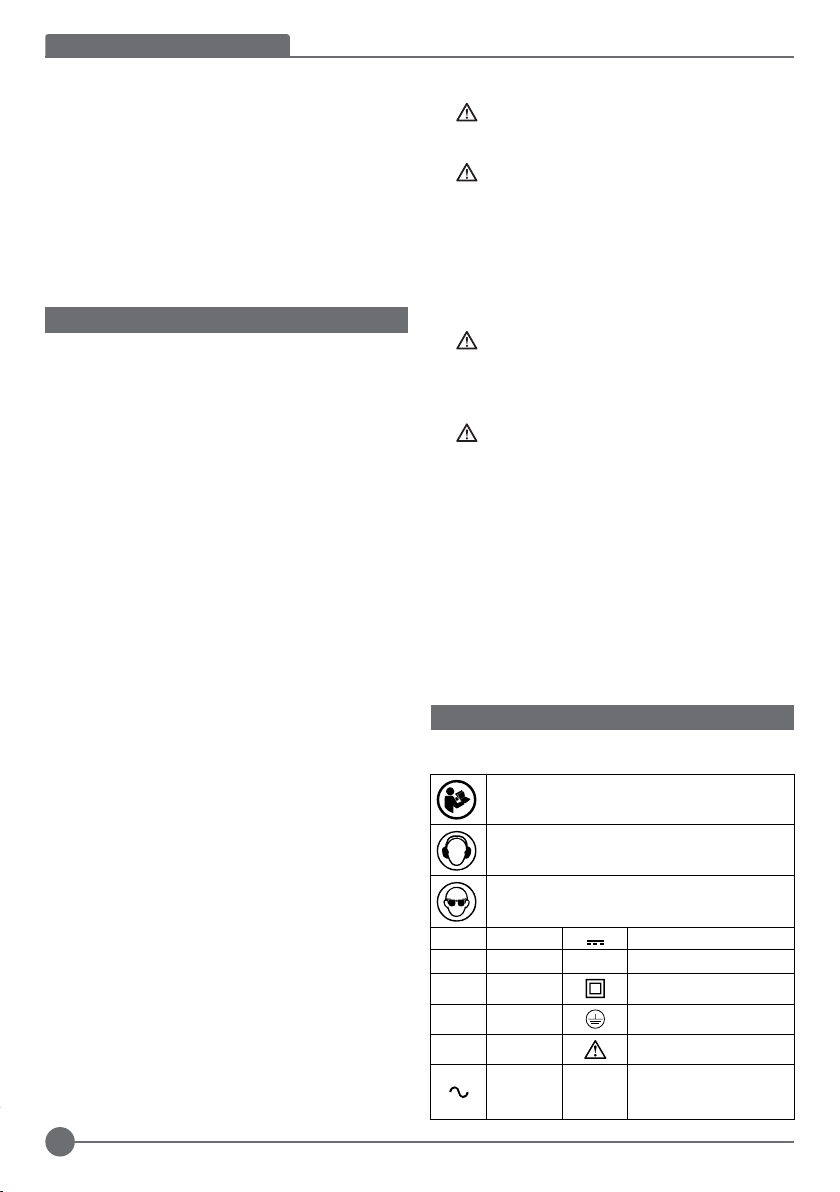
LABELS ON TOOL
The following symbols are shown on the tool along with date
code:
WARNING! To reduce the risk of injury, the user
must read the instruction manual before use.
Wear ear protection.
Wear safety glasses or goggles.
V Volts
A Amperes n
Hz Hertz
W Watts
min minutes
Alternating
Current
Direct Current
No-Load Speed
0
Class II Construction
Earthing Terminal
Safety Alert Symbol
Revolutions or
/min.
Reciprocation per
minute
4
Page 5
Position of Date Code
The Date Code, which also includes the year of manufacture,
is printed into the housing.
Example:
2017 XX JN
Year of manufacturing
PACKAGE CONTENTS
The package contains:
1 Chopsaw
1 355mm Metal Cutting Abrasive Wheel
1 Wheel Wrench
1 Instruction Manual
• Check for damage to the tool, parts or accessories which
may have occurred during transport.
• Take the time to thoroughly read and understand this
manual prior to operation.
ELECTRICAL SAFETY
Your tool is double insulated; therefore no earth wire
is required. Be sure to check that the power supply
corresponds to the voltage on the rating plate.
If the supply cord is damaged, it must be replaced
by the manufacturer or an authorised STANLEY
Service Centre in order to avoid a hazard.
USING AN EXTENSION CABLE
If it is necessary to use an extension cable, please used an
approved extension cable that fits the tool’s power input
specifications. The minimum cross-sectional area of the
conducting wire is 1.5 sq. mm. Cables should be untangled
before reeling up.
Cable cross-sectional
area (mm
2
)
0.75 6
1.00 10
1.50 15
2.50 20
4.00 25
Voltage Amperes Cable rated current (Ampere)
115 0 - 2.0 6 6 6 6 6 10
2.1 - 3.4 6 6 6 6 15 15
3.5 - 5.0 6 6 10 15 20 20
5.1 - 7.0 10 10 15 20 20 25
7.1 - 12.0 15 15 20 25 25 -
12.1 - 20.0 20 20 25 - - -
Cable rated current
(Ampere)
Cable length (m)
7.5 15 25 30 45 60
(Or iginal instructions) ENGLISH
230 0 - 2.0 6 6 6 6 6 6
2.1 - 3.4 6 6 6 6 6 6
3.5 - 5.0 6 6 6 6 10 15
5.1 - 7.0 10 10 10 10 15 15
7.1 - 12.0 15 15 15 15 20 20
12.1 - 20.0 20 20 20 20 25 -
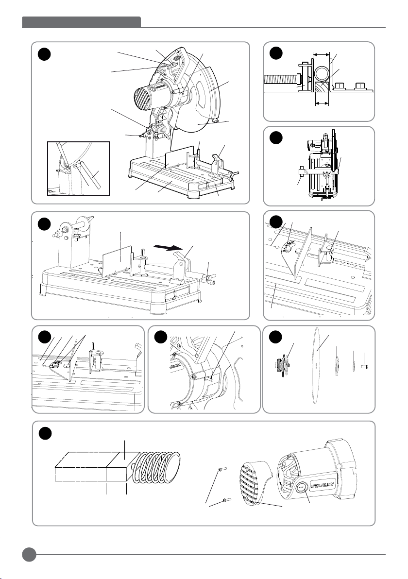
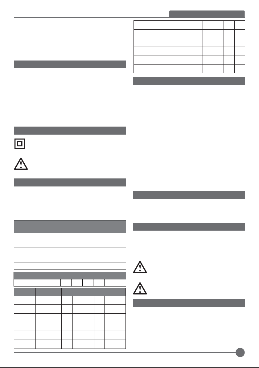
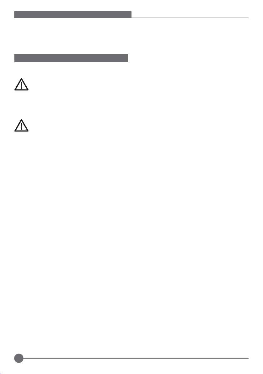
FEATURES (FIG. 1, 4)
This tool includes some or all of the following features.
1. Lock-on button
2. Spark Deflector Screw
3. Spark Deflector
4. Base
5. Fence
6. Vise
7. Polygonal Wrench
8. Crank
9. Vise Level
10. Wheel
11. Guard
12. Spindle Lock
13. Depth Stop Bolt and Jam Nut
14. Trigger Switch with Lock on
15. Padlock Hole
16. Fence Bolts
24. Lock Pin
POWER SUPPLY
Be sure your power supply agrees with the nameplate
marking. A voltage decrease of more than 10% willcause a
loss of power and overheating.
CUTTING CAPACITY
The wide vise opening and high pivot point provide cutting
capacity for many large pieces. Use the cutting capacity chart
to determine total maximum size of cuts that can be made
with a new wheel.
CAUTION: CERTAIN LARGE, CIRCULAR OR
IRREGULA RLY S HAPED OBJECTS MAY
REQUIRE ADDITIONAL HOLDING MEANS IF
THEY CANNOT BE HELD SECURELY IN VISE.
CAUTION: DO NOT CUT MAGNESIUM WITH
THIS TOOL.
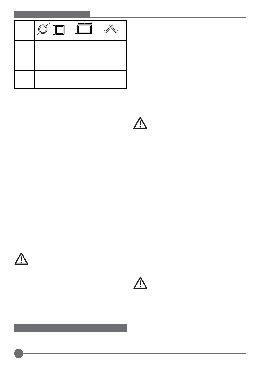
MAXIMUM CUTTING CAPACITY
NOTE: Capacity shown on chart assumes no wheel wear and
optimum fence position.
5
Page 6
ENGLISH (Original instr uctions )
Workpiece
Shape:
90°
Cutting Angle
45°
Cutting Angle
A = 125mm
(4-7/8")
A= 115mm
(4-1/2")
A = 115mm
(4-1/2")
A = 98mm
(3-13/16")
A x B
115mm x 130mm
(4-1/2" x 5-1/8")
102mm x 178mm
(4" x 7")
76mm x 204mm
(3" x 8")
95mm x 105mm
(3-3/4" x 4-1/8")
A = 120mm
(4-3/4")
A = 105mm
(4-1/8")
To Carry (fig. A)
Fold down unit to position where you can carry the saw. Push
in lock pin (24) to lock arm down.
Installation Instruction (fig. C)
Fix the tool on a stable position through fix holes by using 2
M10 bolts.
Un Locking (fig. A)
To unlock tool and raise head, depress motor arm slightly and
pull lock pin (24) out. Motor arm will then pivot upward.
Spark Deflector Adjustment (fig. A)
To best deflect sparks away from surrounding persons and
materials, loosen the screw (2), adjust the spark deflector (3)
and then retighten screw. Do not allow cordset to come into
contact with deflector or sparks as damage to cordset may
occur.
Depth Stop (fig. A)
Depth stop is set at the factory for a new 14” wheel to prevent
wheel from cutting into the supporting surface. To allow more
depth of cut, use the wrench (no provided) to loosen the depth
stop bolt (13) and raise bolt todesired height and then turn jam
nut (13) clockwise until seated firmly on the casting. Securely
tighten the depth stop bolt before use.
CAUTION: When changing to a new wheel,
readjust depth stop to original position to prevent
cutting intosupporting surface.
Trigger Switch with Lock-on(fig. A)
To start the tool, depress the trigger switch (14), then push
lock-on button(1) to keep tool running. To turn the tool off,
depress the trigger again and release the trigger switch. Keep
hands and material from wheel until it has coasted to a
stop.To prevent unauthorized use of tool, install a standard
padlock (not included) into the padlock hole (15) located in the
trigger.
MATERIAL CLAMPING AND SUPPORTING
• Angles are best clamped and cut with both legs resting
against base.
• A spacer block slightly narrower than the work piece can
be used to increase wheel utilization (Fig. B).
• Long work pieces must be supported by a block so it will
be level with top of base (Fig. C). The cut off end should
be free to fall downward to avoid wheel binding.
Vise Operation (fig. D)
The vise (6) has a quick-travel feature. To release the vise
when it is clamped tightly, turn the crank (8) counterclockwise
one or two times to remove clamping pressure.
Lift vise lever (9) up. Pull crank assembly out as far asdesired.
Vise may be pushed forward into work without cranking.
Lower vise lever (9) then tighten vise (6) onwork by using
crank (8).
Fence Operation (fig. E, F)
CAUTION: Turn off and unplug the tool before
making any adjustments or removing or installing
attachments or accessories. Be sure the trigger
switch is in the OFF position.The fence (5) can be
adjusted two ways: to change desired cutting angle
and to change spacing between the fence and vise.
To Change the Desired Cutting Angle
Use the wrench(7) provided to loosen (do not remove) the two
fence bolts (16). Align the desired angle indicator line with
theslot line (17) in the base (4). Securely tighten both fence
bolts before use. For more accurate square cuts, disconnect
the power supply, loosen the two fence bolts, push arm down
until wheel extends into base. Place a square against
thewheel and adjust fence against the square. Securely
tighten both fence bolts before use. When making a miter cut,
the vise (6) may not clamp securely, depending on the
thickness of the workpiece and the miter angle. Other aids
(such as spring, bar or C-clamps) will benecessary to secure
the work piece to the fence when making these cuts.
To Change Spacing between The Fence and Vise
Using the wrench(7) provided, loosen and remove the two
fence bolts (16). Adjust the fence (5) to desired locations.
Insert both fence bolts in provided locations. Securely tighten
both fence bolts before use.
Removal and Installation of Wheels (fig. G, H)
CAUTION: Turn off and unplug the tool before
making any adjustments or removing or installing
attachments or accessories. Be sure the trigger
switch is in the OFF position. Do not make any
adjustment while the wheel is in motion. Do not
make any adjustment while chop saw is plugged
into power supply.
1. Push in spindle lock (12) and rotate wheel (10) by hand
until wheel lock lever engages slot in inside flange(18) to
lock wheel. Loosen the bolt (19) counterclockwise in the
center of the abrasive wheel with the M10 Polygonal
wrench (7). Bolt has right-hand thread.
6
Page 7
2. Remove the bolt (19), washer (20), outside flange (21)
and old wheel (10).
3. Make sure flange surfaces are clean and flat. Install the
new abrasive wheel by reversing the above steps.
4. Do not overtighten bolt.
WARNING: Check the work surface that the chop
saw rests on when replacing with a new abrasive
wheel. It is possible that the wheel may contact
ANY ITEMS OR STRUCTURE THAT EXTENDS
ABOVE work surface (under the base) when the
arm is fully lowered.
WARNING: Always keep the screw attached to the guard and
make sure the center guard in the right position after replacing
wheel and before use, to protect user from high speed rotating
wheel.
Operation Tips for More More Accurate Cuts
• Allow the wheel to do the cutting. Excessive force will
cause the wheel to glaze reducing cutting efficiency and/or
to deflect causing inaccurate cuts.
• Properly adjust fence angle.
• Make sure material is laying flat across base.
• Properly clamp material to avoid movement and vibration.
Motor Brush Inspection and Replacement (fig.I)
WARNING:Turn off and unplug the tool. Be sure the
trigger switch is in the OFF position. Brushes should
be regularly inspected for wear. To inspect brushes,
unscrew the two end cap screws (22) and remove
end cap (23). Remove brush cap (25). Brushes (26)
should slide freely in brush box. If brushes are
worndown to .3” (8mm) as shown in Figure I they
should be replaced. To reinstall, push new brush
back into brushbox. If replacing existing brush,
maintain same orientation as when removed.
Replace the brush cap (do not overtighten).
Replace end cap and two screws. Tighten securely.
Tool Care
Avoid overloading the machine.Overloading will result in a
considerable reduction in speed and efficiency and the unit
will become hot. In this event,run the machine at no load for a
minute or two until cooled to normal working temperature by
the built in fan. Switching your machine on and off whilst under
load will considerably reduce the life of the switch.
Important
To ensure product SAFETY and RELIABILITY, repairs,
maintenance and adjustment (other than those listed in this
manual) should be performed by authorized service centers or
other qualified organizations, always-using identical
replacement parts. Unit contains no user serviceable parts
inside.Blowing dust and grit out of the main housing by means
of an air hose is recommended and may be done as often as
dirt is seen collecting in and around the air vents. Always wear
proper eye and respiratory protection.
(Or iginal instructions) ENGLISH
NOTE: Unit may be converted to a 3-wire twist lock cord set at
an authorized service center.
MAINTENANCE
Your STANLEY corded/cordless appliance/tool has been
designed to operate over a long period of time with a minimum
of maintenance. To ensure satisfactory operations, the tool
must be maintained and cleaned regularly
WARNING: To reduce the risk of injury, turn unit
off and disconnect machine from power source
before installing and removing accessories,
before adjusting or changing set-ups or when
making repairs. Be sure the trigger switch is in the
OFF position. An accidental start-up can cause
injury.
• This machine is not user-serviceable. If problems occur
contact an authorised repair agent.
• The tool will automatically switch off when the carbon
brushes are worn.
WARNING! Before performing any maintenance on corded/
cordless power tools:
• Switch off and unplug the appliance/tool.
• Or switch off and remove the battery from the appliance/
tool if the appliance/tool has a separate battery pack.
• Or run the battery down completely if it is integral and then
switch off.
• Unplug the charger before cleaning it. Your charger does
not require any maintenance apart from regular cleaning.
• Regularly clean the ventilation slots in your appliance/
tool/ charger using a soft brush or dry cloth.
• Regularly clean the motor housing using a damp cloth. Do
not use any abrasive or solvent-based cleaner.
• Regularly open the chuck and tap it to remove any dust
from the interior (when fitted).
Lubrication
Stanley power tools are properly lubricated at the
factory and are ready for use. Tools should be
relubricated regularly , depending on usage. This
lubrication should only be attempted by trained
power tool repair persons, such as those at Stanley
service centers or by other qualified service
personnel.
Closed-type, grease-sealed ball bearings are used
throughout. These bearings have sufficient lubrication packed
in them at the factory to last the life of the chop saw.
Cleaning
Warning: unplug the tool before you use a cloth to
clean the housing.With the motor running, blow dirt
and dust out of all air vents with dry air at least once
a week. Wear safety glasses when performing this.
Exterior plastic parts may be cleaned with a damp
cloth and mild detergent. Although these parts are
highly solvent resistant, NEVER use solvents.
7
Page 8
ENGLISH (Original instr uctions )
Blowing dust and grit out of the main housing by
means of an air hose is recommended and may be
done as often as dirt is seen collecting in and
around the air vents. Always wear proper eye and
respiratory protection.
ACCESSORIES
The performance of any power tool is dependent upon the
accessory used. Stanley accessories areengineered to high
quality standards and are designed to enhance the
performance of power tool.
Note: Accessory must be rated for use at speed equal to or
higher than nameplate RPM of tool with which it is being used.
CAUTION: The use of any other accessory not
recommended for use with this tool could be
hazardous.Use only high-strength Type 1 organic
bonded wheels rated 4100 rpm or higher.
Recommended accessories for use with your tool
are available at extra cost from your local dealer or
authorized service center.
Protecting the Environment
Separate collection. This product must not be
disposed of with normal household waste.
Should you find one day that your STANLEY product needs
replacement, or if it is of no further use to you, do not dispose
of it with household waste. Make this product available for
separate collection.
STANLEY provides a facility for the collection and
recycling of STANLEY products once they have
reached the end of their working life. To take
advantage of this service please return your product to any
authorised repair agent who will collect them on our behalf.
You can check the location of your nearest authorised repair
agent by contacting your local STANLEY office at the address
indicated in this manual. Alternatively, a list of authorised
STANLEY repair agents and full details of our after-sales
service and contacts are available on the Internet at:
www.2helpU.com.
Notes
STANLEY’s policy is one of continuous improvement to our
products and as such, we reserve the right to change product
specifications without prior notice.
Standard equipment and accessories may vary by country.
Product specifications may differ by country.
Complete product range may not be available in all countries.
Contact your local STANLEY dealers for range availability.
TECHNICAL DATA
CHOP SAW SSC22
Voltage V 220-240
Frequency Hz 50/60
Power input W 2200
No-load speed min 3800
Max diameter mm 355
Weight kg 15.5
Level of sound pressure according to EN 60745:
Sound pressure (L
Sound power (LWA) 107.5 dB(A), uncertainty (K) 3 dB(A)
Vibration emission value ah:
ah = m/s² 4.9
Uncertainty K = m/s² 1.5
) 87.0 dB(A), uncertainty (K) 3 dB(A)
pA
Vibration
The declared vibration emission values stated in the technical
data and the declaration of conformity have been measured in
accordance with a standard test method provided by EN
61029 and may be used for comparing one tool with another.
The declared vibration emission value may also be used in a
preliminary assessment of exposure.
Warning! The vibration emission value during actual use of the
power tool can differ from the declared value depending on
the ways in which the tool is used. The vibration level may
increase above the level stated.
When assessing vibration exposure to determine safety
measures required by 2002/44/EC to protect persons regularly
using power tools in employment, an estimation of vibration
exposure should consider, the actual conditions of use and the
way the tool is used, including taking account of all parts of
the operating cycle such as the times when the tool is
switched off and when it is running idle in addition to the
trigger time.
8
Page 9

EC declaration of conformity
MACHINERY DIRECTIVE
SSC22 Chop Saw
STANLEY declares that these products described under
"technical data" are in compliance with: 2006/42/EC,
EN 61029-1:2009+A11:2010, EN 61029-2-10:2010
+A11:2013
These products also comply with Directive 2014/30/EU and
2011/65/EU.
For more information, please contact STANLEY at the
following address or refer to the back of the manual.
The undersigned is responsible for compilation of the
technical file and makes this declaration on behalf of
STANLEY.
R.Laverick
Engineering Manager
STANLEY , Europe, Egide Walschaertsstraat14-18,
2800 Mechelen, Belgium
06.2017
(Or iginal instructions) ENGLISH
TWO YEAR WARRANTY
If your STANLEY product becomes defective due to faulty
materials or workmanship within 24 months from the date of
purchase, STANLEY guarantees to replace all defective parts
free of charge or – at our discretion – replace the unit free of
charge provided that:
• The product has not been misused and has been used in
accordance with the instruction manual;
• The product has been subject to fair wear and tear;
• Repairs have not been attempted by unauthorized
persons;
• Proof of purchase is produced.
• The STANLEY product is returned complete with all original
components
• The product hasn’t been used for hire purposes
If you wish to make a claim, contact your seller or check the
location of your nearest authorised STANLEY repair agent in
the STANLEY catalogue or contact your local STANLEY office
at the address indicated in this manual. A list of authorised
STANLEY repair agents and full details of our after sales
service is available on the internet at: www.2helpU.com
9
Page 10
РУССКИЙ
(Перевод с оригинала инструкции)
Назначение
Ваша монтажная пила STANLEY SSC22 предназначена для
резки стальных материалов различного профиля.
Данный ин струмент пр едназначен дл я
профессионального использования.
ИНСТРУКЦИИ ПО ТЕХНИКЕ БЕЗОПАСНОСТИ
Общие правила безопасности при работе с
электроинструментами
ВНИМАНИЕ! Внимательно прочтите все
инструкции по безопасности и руководство
по эксп луатации. Несоблюдение всех
перечисленных ниже правил безопасности и
инструкций может привести к поражению
электрическим током, возникновению пожара
и/или получению тяжёлой травмы.
ВНИМАНИ Е! Пр и испол ьзо вани и
электрических инструментов соблюдение
правил по технике безопасности и следование
данным инструкциям позволит снизить
ве роятно сть возникн ове ния пож ара ,
поражения электрическим током и получения
травм. Перед использованием данного
электроинструмента внимательно прочтите
настоящие инструкции и сохраните их для
последующего использования.
Сохраните все инструкции по безопасности и
руководство по эксплуатации для их дальнейшего
использования. Термин «Электроинструмент» во всех
привёденных ниже указаниях относится к Вашему
сетевому (с кабелем) или аккумуляторн ому
(беспроводному) электроинструменту.
1. Безопасность рабочего места
а. Содержите рабочее место в чистоте и хорошо
освещенным. Беспорядок на рабочем месте или
отсутствие освещения рабочего места может
привести к аварии.
b. Не работайте с электроинструментом в месте
хранения взрывоопасных материалов, например,
в присутствии огнеопасных жидкостей, газов или
пыли. Электрические инструменты создают искры,
которые могут воспламенить пыль или пары.
с. Дети и посторонние лица должны находиться как
можн о дальш е во в ремя р аботы с
электроинструментом. Вы можете отвлечься и
потерять контроль.
2. Электробезопасность
а. В ил ка эл ектр ои нс тру ме нта д ол жн а
со ответ ств оват ь ро зет ке. Н ико гда не
модифицируйте вилку каким-либо образом. Не
используйте ник акие вилки-переходники с
за земле нными (за мкнут ыми на з емлю)
электроинструментами. Вилки и розетки, которые
не подвергались никаким изменениям снижают риск
поражения электрическим током.
b. Избегайте контакта тела с зазе мленными
поверхностями, такими как трубы, радиаторы,
плиты и холодильники. Существует повышенный
риск поражения электрическим током, если ваше
тело заземлено.
с. Избегайте любого воздействия дождя или влаги
на элек троинструменты. Вода, попавшая в
электроинструмент, увеличивает риск поражения
электрическим током.
d. Аккуратно обращайтесь со шнуром питания.
Никогда не используйте шнур питания для
переноски, перемещения или извлечения вилки
из розетки. Держите шнур вдали от источников
тепла, масла, острых краев или движущихся частей.
Поврежденные или запутанные шнуры увеличивают
риск поражения электрическим током.
е. При работе с электроинструментом на улице,
используйте удлинитель, п одходящий для
наружного использования. Использование кабеля,
пригодного для использования на открытом воздухе,
снижает риск поражения электрическим током.
f. П ри н ео бх од им ос ти ра бо ты с
электроинструме нтом во влажной среде ,
используйте устройство защитного отключения
(УЗО). Использование УЗО снижает риск поражения
электрическим током. ПРИМЕЧАНИЕ: Термин
«устройство защитного отключения (УЗО)» может
быть заменён на «аварийный прерыватель
заземления» или «автоматический выключатель тока
утечки».
3. Личная безопасность
a. Будьте внимательны, смотрите, что вы делаете,
используйте здравый смысл при работе с
эл ектр оинст рум ент ом. Н е испо льзу йте
электроинструмент, если вы устали или находитесь
под влиянием наркотиков, алкоголя или лекарств.
Малейш ая н еостор ожность при работе с
электроинструментом может привести к серьезным
травмам.
b. Используйте средства индивидуальной защиты.
Всегда надевайте защитные очки. Другое
защитное оборудование, включая респиратор,
ботинки на нескользящей подошве, защитный
шлем или средства защиты органов слуха,
используемые в надлежащих условиях, уменьшат
риск получения травмы.
с. Для предотвра щения случайного з апуск а,
убедитесь, что переключатель находится в
выключенном положении перед подключением к
источнику питания и/или аккумуляторной
батарее, поднятия или переноски инструмента. Не
переносите электроинструмент с пальцем на
выключателе и не включайте питание на инструмент с
включенным выключателем, что может привести к
несчастному случаю.
10
Page 11

d. Перед включением электроинструмента снимайте
регулировочный или гаечный ключ. Гаечный или
регулировочный ключ, оставленный на вращающейся
части электроинструмента, может привести к травме.
е. Не тянитесь. Сохраняйте правильную стойку и
баланс все врем я. Это позволяет лучше
контролировать инструмент в неожиданных
ситуациях.
f. Одевайтесь правильно. Не надевайте свободную
одежду или украшения. Держите волосы, одежду
и перчатки вдали от движущихся частей.
Свободная одежда, украшения или длинные волосы
могут попасть в движущиеся части.
g. Если имеются устройства для подключения
пылесборника или вытяжки, убедитесь в том, что
они подсоединены и используются правильно.
Использование пылесборника снижает вероятность
возникновения рисков, связанных с пылью.
4. Использование и уход за электроинструментом
a. Н е п ерег ру жайт е э лектрои нс тру мент.
Используйте под ходящий электричес кий
инструмент для соответствующего применения.
Правильно п одобранный электроинструмент
позволит выполнить работу лучше и безопаснее при
скорости, для которой он был разработан.
b. Не используй те электроинст румент, если
переключатель не может его включить и
выключить. Любой электроинструмент, который
нельзя контролировать с помощью переключателя,
опасен и должен быть отремонтирован.
c. Отключите кабель питания от источника питания
и/или аккумуляторный блок от электрического
инструмента перед выполнение м любых
регулировок, замены принадлежностей или при
хра не нии эле кт роинстру ме нта . Такие
профилактические меры безопасности уменьшают
риск непреднамеренного запуска электрического
инструмента.
d. Храните неиспользуемые электроинструменты в
недоступном для детей месте и не позволяйте
лицам, не знакомым с электроинструментом или
да нными инстр укци ями, ра бота ть с
электроинструментом. Электроинструменты опасны в
руках неопытных пользователей.
е. Поддержание электроинструмента. Проверяйте
разрегулированность или cоединение подвижных
частей, поломки частей и любые другие условия,
кото рые мог ут п овли ять на раб оту
электроинструмента. При наличии повреждения,
отремонтируйте электроинст румент перед
использованием. Многи е несчастные случаи
являютс я с ледствием плохого уход а за
электроинструментом.
(Перевод с оригинала инструкции)
f. Держите режущий инструмент острым и чистым.
Хорошо ухоженный режущий инструмент с острыми
режущими кромками легче контролировать.
g. И сп о ль з уй т е э л ек т р о ин ст р ум е нт ,
принадлежности, насадки и т.д. в соответствии с
этими инструкциями, принимая во внимание
рабочие условия и характер выполняемой
работы Использование электроинструмента иным
способом может привести к опасным ситуациям.
5. Обслуживание
а. Обеспечьте, чтобы обслуживание и ремонт
ваш его электрои нструмента проводилс я в
авторизованном сервисном центре по ремонту с
использованием только оригинальных запасных
час тей. Это станет гарантией безопасности
электроинструмента.
РУССКИЙ
ИНСТРУКЦИИ ПО БЕЗОПАСНОСТИ ПРИ РАБОТЕ
МОНТАЖНЫМИ ПИЛАМИ
• Всегда надевайте защитные очки и респиратор.
• Перед использованием, осмотрите режущий диск
на предмет выявления трещин или дефектов. При
обнаружении дефектов – замените диск. Также
всякий раз проверяйте режущий диск при
подозрении, что пила могла упасть. Дефекты
поверхности могут стать причиной поломки диска.
• При включении пилы с установленным новым
диском или если Вы не уверены в хорошем
состоянии диска, установите пилу в хорошо
защищённой зоне и дайте ей поработать в
течение 1 минуты. Если на диске имеются скрытые
трещины или повреждения, он должен сорваться с
крепления меньше чем за минуту. Никогда не
включайте инструмент, если на линии диска
находятся люди. Это правило включает в себя и
оператора.
• Избегайте резкого отскока режущего диска и
грубого обращения с диском во время работы.
Если это произошло, выключите инструмент и
проверьте режущий диск на наличие сколов и
трещин.
• Регулярно проводите чистку Вашей монтажной
пилы, следуя инструкциям в данном руководстве
по эксплуатации.
• Не снимайте защитные кожухи или основание.
• ВСЕГДА НАДЁЖНО ЗАКРЕПЛЯЙТЕ ЗАГОТОВКУ,
ИС ПОЛ ЬЗУЯ ДЛЯ ЭТОГО ТИСКИ ИЛ И
СПЕЦИАЛЬНОЕ ЗАЖИМНОЕ УСТРОЙСТВО. В
зависимости от размера и формы заготовки можно
также использовать вспомогательные средства, такие
как пружина, брусок или зажимные скобы. Будьте
особенно внимательны при выборе и установке
зажимных устройств и перед работой всегда делайте
пробный запуск.
11
Page 12

РУССКИЙ
• Используйте диски 14" Типа 1, рассчитанные на
скорость 4100 об/мин и выше.
• Прежде чем дотрагиваться до отрезанных частей,
дайте им полностью остыть.
• Не разрешается использовать данный инструмент
для резания древесины или пластиков.
• ЗА ПРЕЩЕ НО ИСПОЛЬ ЗОВАНИ Е ДА ННОГО
ИНСТРУМЕНТА ДЛЯ РЕЗКИ МАГНИЯ.
• В случае застревания фрагментов заготовки между
пильным диском и защитными кожухами отключите
инструмент от источника питания. Удалите
застрявшие частицы и установите на место пильный
диск.
• Используйте монтажную пилу только в хорошо
вентилируемых помещениях.
• Всегда выключайте монтажную пилу перед
удалением какой-либо детали с основания.
• НИ В КОЕМ СЛУЧАЕ НЕ РЕЖЬТЕ ПРЕДМЕТЫ,
НАХ ОДЯЩ ИЕ СЯ П ОД Э ЛЕ КТРИЧЕСК ИМ
НАПРЯЖЕНИЕМ.
• Не используйте с данным инструментом режущие
диски для дисковых пил или другие отрезные
диски с зубьями. Это может привести к получению
тяжёлой травмы.
• НЕ ИСПОЛЬЗУЙТЕ ДАННЫЙ ИНСТРУМЕНТ ВБЛИЗИ
ОТ ГОРЮЧИХ ЖИДКОСТЕЙ, ГАЗОВ ИЛИ ПЫЛИ.
Искры или раскаленная стружка, образующаяся в
резу льтате резк и, или искрение щёток
электродвигателя могут вызвать воспламенение
горючих материалов.
• Не используйте боковую сторону абразивного диска
в качестве зачищающего инструмента. Это
значительно сократит срок службы диска и создаст
опасную ситуацию. Диск может сорваться с
крепления.
• ПРЕ ДУПРЕЖДЕНИЕ: При использовани и
инстру мента надев айте противо шумо вые
науш ники. При неко торы х условия х и
пр одо лжи тел ьно сти испо льзо ван ия, шум,
производимый данным инструментом, может
способствовать потере слуха.
• ПРЕДУПРЕЖДЕНИЕ: Отражатель искр сильно
нагревается. Не прикасайтесь к нему и не
регулируйте, пока он не остынет. Следите, чтобы
кабель и материалы находились на расстоянии от
отражателя искр.
• Избегайте продолжительного контакта с пылью,
вырабатываемой при шлифовании, пилении,
зачистке, сверлении и выполнении других
строительных работ. Надевайте защитную одежду
и промывайте незащищённые участки кожи
водой и мылом. Попадание пыли в рот, глаза или
на кож у может способствов ать усвоению
вредоносных химических веществ.
• ВНИМАНИЕ: Всегда используйте пылезащитный
респиратор, одобренный NIOSH (Национальный
(Перевод с оригинала инструкции)
18
институт по охране труда и промышленной гигиене
США)/OSHA (Федеральное Агентство по Охране Труда
и Здоровья США). Следите за тем, чтобы лицо и тело
было в стороне от линии выброса пыли. В целях
обеспечения безопасности на Вашей монтажной пиле
высокой мощности 14" (355 мм) имеются следующие
предупреждающие знаки:
• ДЛЯ ОБЕСПЕЧЕНИЯ БЕЗОПАСНОЙ РАБОТЫ
ПРОЧТИТЕ РУКОВОДСТВО ПО ЭКСПЛУАТАЦИИ.
• НЕ ИСПОЛЬЗУЙТЕ ЗУБЧАТЫЕ ПИЛЬНЫЕ ДИСКИ.
• ИС ПОЛЬЗУЙТ Е ТО ЛЬКО АРМИРО ВАННЫЕ
РЕЖУЩИЕ ДИСКИ С РАСЧЁТНЫМИ ДАННЫМИ 4100
ОБ/МИН ИЛИ ВЫШЕ.
• ПРИ ТЕХНИЧЕСКОМ ОБСЛУЖИВАНИИ ДАННОГО
ИНС ТР УМЕНТА И СП ОЛЬ ЗУЙТЕ ТОЛ ЬКО
ИДЕНТИЧНЫЕ ЗАПАСНЫЕ ЧАСТИ.
• ВСЕГД А: НАДЕВА ЙТЕ ЗАЩ ИТНЫЕ ОЧК И,
РЕСПИРАТОР, ИСПОЛЬЗУЙТЕ ЗАЩИТНЫЕ КОЖУХИ,
ДЛЯ ЗАЖИМА ЗАГОТОВКИ ИСПОЛЬЗУЙТЕ ТИСКИ.
• НЕ ПОДВЕРГАЙТЕ ВОЗДЕЙСТВИЮ ДОЖДЯ И НЕ
ИСПОЛЬЗУЙТЕ ВО ВЛАЖНЫХ УСЛОВИЯХ.
• ИСПОЛЬЗУЙ ТЕ ТОЛЬКО РЕЖ УЩИЕ ДИСКИ
ТОЛЩИНОЙ НЕ БОЛЕЕ 3,0 ММ И МАКСИМАЛЬНЫМ
ДИАМЕТРОМ 355 ММ.
МАРКИРОВКА ИНСТРУМЕНТА
Помимо кода даты на инструменте имеются следующие
знаки:
ВНИМАНИЕ! Полное ознакомление с руководством
по эксплуатации перед использованием инструмента
снизит риск получения травмы.
Используйте средства защиты органов слуха.
Надевайте защитные очки или маску.
V
Вольт
A
Ампер
Hz
Герц
W
Ватт
min
минут
Переменный
ток
Место положения кода даты
Код даты, который также включает в себя год
изготовления, отштампован на поверхности корпуса
инструмента.
Пример:
2017 XX JN
Год изготовления
Постоянный ток
n
Скорость без нагрузки
0
Конструкция Класса II
Клемма заземления
Символ опасности
Кол-во оборотов или
/min.
шагов в минуту
Page 13

КОМПЛЕКТ ПОСТАВКИ
В упаковку входят:
1 Монтажная пила
1 355 мм Абразивный диск для резки металла
1 Ключ для установки диска
1 Руководство по эксплуатации
• Проверьте инструмент, детали и дополнительные
приспособления на наличие повреждений, которые
могли произойти во время транспортировки.
• Перед началом работы необходимо внимательно
прочитать настоящее руководство и принять к
сведению содержащуюся в нем информацию.
ЭЛЕКТРОБЕЗОПАСНОСТЬ
Данный инструмент защищён двойной
изоляцией, что исключает потребность в
за земляю щем пров оде. Сле дите за
напряжением электрической сети, оно должно
соответствовать величине, обозначенной на
информационной табличке инструмента.
Во избежание несчастного случая замена
повреждённого кабеля питания должна
производиться только на заводе-изготовителе
или в авторизованном сервисном центре
STANLEY.
ИСПОЛЬЗОВАНИЕ УДЛИНИТЕЛЬНОГО КАБЕЛЯ
При необходимости использования удлинительного
кабеля, используйте только утверждённые кабели
промышленного изготовления, рассчитанные на
мощность не меньшую, чем потребляемая мощность
данного инструмента. Минимальный размер проводника
должен составлять 1,5 мм². При использовании
кабельного барабана, всегда полностью разматывайте
кабель.
Поперечное сечение
проводника (мм
2
)
0,75 6
1,00 10
1,50 15
2,50 20
4,00 25
Номинальный ток
кабеля (Ампер)
Длина кабеля (м)
7,5 15 25 30 45 60
(Перевод с оригинала инструкции)
Напряжение
110-127 0 - 2,0 6 6 6 6 6 10
220-240 0 - 2,0 6 6 6 6 6 6
СОСТАВНЫЕ ЧАСТИ (Рис. 1, 4)
Данный инструмент может содержать все или некоторые
из перечисленных ниже составных частей:
1. Кнопка блокировки пускового выключателя
2. Винт отражателя искр
3. Отражатель искр
4. Основание
5. Направляющий упор
6. Зажим
7. Полигональный ключ
8. Ручка
9. Рычаг зажима
10. Режущий диск
11. Защитный кожух
12. Блокировка шпинделя
13. Болт ограничителя глубины реза и стопорная гайка
14. Курковый пусковой выключатель с функцией
блокировки
15. Отверстие для навесного замка
16. Болты направляющего упора
24. Стопорный штифт
ПИТАНИЕ ЭЛЕКТРОСЕТИ
Убедитесь, что питание электросети полностью
соответствует указанному на фирменной табличке
инструмента. Уменьшение напряжения более чем на 10%
повлечет за собой снижение мощности и перегрев
инструмента.
РЕЖУЩАЯ СПОСОБНОСТЬ
Широкий проём зажимного приспособления и высоко
расположенная ось поворота обеспечивает возможность
резки крупных заготовок самого различного типа. Для
определения максимального размера прореза, который
может быть сделан новым диском, обратитесь к таблице
режущей способности.
Ампер Номинал кабеля (Ампер)
2,1 - 3,4 6 6 6 6 15 15
3,5 - 5,0 6 6 10 15 20 20
5,1 - 7,0 10 10 15 20 20 25
7,1 - 12,0 15 15 20 25 25 -
12,1 - 20,0 20 20 25 - - -
2,1 - 3,4 6 6 6 6 6 6
3,5 - 5,0 6 6 6 6 10 15
5,1 - 7,0 10 10 10 10 15 15
7,1 - 12,0 15 15 15 15 20 20
12,1 - 20,0 20 20 20 20 25 -
РУССКИЙ
19
Page 14

РУССКИЙ
(Перевод с оригинала инструкции)
ПРЕДУПРЕЖДЕНИЕ: ДЛЯ РЕЗКИ НЕКОТОРЫХ
КРУПНЫХ ЭЛЕМЕНТОВ ОКРУГЛОЙ ИЛИ
НЕПРАВИЛЬНОЙ Ф ОР МЫ МО ЖЕ Т
ПОТРЕ БОВ АТЬ СЯ И СП ОЛ ЬЗ ОВ АН ИЕ
Д О П О Л Н И Т Е Л Ь Н Ы Х
ЗА ЖИМ ОВ- ФИКСАТОРО В ( В С ЛУЧ АЕ
НЕ ВОЗ МОЖНОС ТИ ИХ НАДЁ ЖНОГО
ЗАКРЕПЛЕНИЯ В ТИСКАХ).
ПРЕДУПРЕ ЖДЕНИЕ: НЕ ИСПОЛЬЗУ ЙТЕ
ДАННЫЙ ИНСТРУМЕНТ ДЛЯ РЕЗКИ МАГНИЯ!
МАКСИМАЛЬНАЯ РЕЖУЩАЯ СПОСОБНОСТЬ
ПРИМЕЧАНИЕ: В параметры приведённой в таблице
режущей способности включены диск без признаков
износа и оптимальное положение направляющего упора.
Форма
заготовки:
Угол реза
90°
Угол реза
45º
A = 125мм
(4-7/8")
A = 115мм
(4-1/2")
A = 115мм
(4-1/2")
A = 98мм
(3-13/16")
A x B
115мм x 130мм
(4-1/2" x 5-1/8")
102мм x 178мм
(4" x 7")
76мм x 204мм
(3" x 8")
95мм x 105мм
(3-3/4" x 4-1/8")
A = 120мм
(4-3/4")
A = 105мм
(4-1/8")
Переноска (Рис. А)
Сложите инструмент в положение, которое позволяет
переноску. Нажмите на стопорный штифт (24) для
блокировки пильной головки в нижнем положении.
Инструкции по установке (Рис. С)
Зафиксируйте инструмент на устойчивой поверхности,
используя отверстия в основании и 2 болта М10.
Разблокировка (Рис. А)
Чтобы разблокировать инструмент и поднять его
пильную головку, слегка нажмите на неё и вытащите
стопорный штифт (24). Пильная головка будет подана
вверх.
Настройка отражателя искр (Рис. А)
Для наилучшей защиты находящихся поблизости людей
и материалов от искр, ослабьте винт (2), отрегулируйте
отражатель искр (3), после чего вновь затяните винт. Не
допускайте контакта электрокабеля с отражателем искр,
а также попадания искр на кабель, так как это может
привести к его повреждению.
Ограничитель глубины реза (Рис. А)
Огран ичитель глуб ины реза наст роен на
заводе-изготовителе для использования с новым 14"
диском, чтобы предотвратить врезание диска в опорную
поверхность. Чтобы увеличить глубину реза, плоским
ключом (не входит в комплект поставки) ослабьте болт
ограничителя глубины реза (13), поднимите болт на
нужную высоту и заверните стопорную гайку (13) по
часовой стрелке, пока она не сядет до упора на корпусе
болта. Надёжно затягивайте болт ограничителя глубины
реза перед началом работы.
ПРЕДУПРЕЖДЕНИЕ: Перед сменой диска
установите ограничитель глубины реза в
первоначальное положение, чтобы избежать
врезания диска в опорную поверхность.
Курковый пусковой выключатель с функцией
блокировки (Рис. А)
Для блокировки инструмента в рабочем состоянии для
непрерывной работы нажмите на курковый выключатель
(14), затем на кнопку блокировки (1). Чтобы выключить
инструмент нажмите и отпустите курковый пусковой
вы клю чател ь. Не прик асайтесь руками и
обрабатываемым материалом к диску до его полной
остановки. Для предотвращения использования
инструмента посторонними лицами, установите в
отверстие (15) в пусковом выключателе стандартный
навесной замок (не входит в комплект поставки).
ЗАЖИМ И ОПОРА ДЛЯ ЗАГОТОВКИ
• Для прижима и резки уголка обе его полки должны
лежать на основании.
• Для увеличения степени использования диска можно
использовать распорный блок, немного более узкий,
чем заготовка (Рис. В).
• В качестве опоры для длинных заготовок должен
использоваться блок, для этого он должен находиться
на одном уровне с верхней частью основания (Рис. С).
Во избежание заедания диска отрезаемый конец
заготовки должен свободно падать вниз.
Работа c зажимом (Рис. D)
Конструкция зажима (6) позволяет производить быстрое
его перемещение. Чтобы ослабить затяжку зажима,
поверните ручку (8) против часовой стрелки на один или
два оборота для снятия усилия затяжки.
Поднимите рычаг зажима (9) вверх. Вытяните ручку до
упора. Зажим может быть вытянут без проворачивания
ручки. Опустите рычаг зажима (9), после чего затяните
зажим (6) с помощью ручки (8).
Работа с направляющим упором (Рис. E, F)
ПРЕДУПРЕЖДЕНИЕ: Перед каждой операцией
регулировки или сня тием/ус танов кой
принадлежностей или насадок, выключайте
электроинструмент и отсоединяйте его от
источника питания. Убедитесь, что клавиша
пускового выключателя находится в положении
ВЫК Л. Направляющий упор (5) можно
отрегулировать двумя способами: изменив угол
резания или расстояние между направляющим
упором и зажимом.
14
Page 15

Изменение угла резания
Ослабьте (не извлекая) два болта направляющего упора
(16), используя ключ (7), входящий в комплект поставки
инструме нта. Совм естите указатель ную риску
требуемого вам угла с прорезью (17) в основании (4).
Прежде чем начать работать, надёжно затяните оба болта
направляющего упора. Для выполнения более точных
прямых резов, отключите пилу от источника питания,
ослабьте оба болта направляющего упора и опустите
пильную головку вниз, пока диск не достигнет
основания. Прижмите угольник к диску и отрегулируйте
по угольнику направляющий упор. Прежде чем начать
работать, надёжно затяните оба болта направляющего
упора. При выполнении резов со скосом зажим (6) может
не затягиваться до упора – это будет зависеть от
толщины заготовки и градуса угла скоса. При
вы пол нени и п одо бны х р езо в необходи мо
использование вспомогательных средств (таких как
пружина, брусок или зажимные скобы) для надёжной
фиксации заготовки на направляющем упоре.
Изменение расстояния между направляющим
упором и зажимом
Ослабьте и извлеките два болта направляющего упора
(16), используя ключ (7), входящий в комплект поставки
инструмента. Установите направляющий упор (5) на
нужное расстояние. Вставьте оба болта направляющего
упора в предусмотренные для них отверстия. Прежде
чем начать работать, надёжно затяните оба болта
направляющего упора.
Снятие и установка диска (Рис. G, H)
ПРЕДУПРЕЖДЕНИЕ: Перед каждой операцией
регул ировк и или сняти ем/ус танов кой
принадлежностей или насадок, выключайте
электроинструмент и отсоединяйте его от
источника питания. Убедитесь, что клавиша
пускового выключателя находится в положении
ВЫКЛ. Не меняйте настроек, пока режущий
диск находится в движении. Не производите
настройку или регулировку, если монтажная
пила подключена к источнику питания.
1. Нажмите на рычаг блокировки шпинделя (12) и
проворачивайте диск (10) рукой до тех пор, пока
рычаг блокировки диска не войдет в зацепление с
пазом внутреннего фланца (18) для фиксации.
Используя полигональный ключ М10 (7), ослабьте
против часовой стрелки болт (19), находящийся в
цент ре абра зивно го диск а. Болт им еет
правостороннюю резьбу.
2. Удалите болт (19), шайбу (20), снимите внешний
фланец (21) и старый диск (10).
3. Убедитесь, что поверхность фланца чистая и ровная.
(Перевод с оригинала инструкции)
Установите новый абразивный диск, выполнив все
указанные вы ше опер ации в обратной
последовательности.
4. Не затягивайте болт слишком туго.
ВНИМАНИ Е: При устано вке но вого
абразивного диска, проверьте рабочую
поверхность, на которой установлена
монтажная пила. Существует вероятность
касания диском КАКОЙ-ЛИБО ДЕТАЛИ ИЛИ
ЭЛЕМЕНТА КОНСТРУКЦИИ, ВОЗВЫШАЮЩЕЙСЯ
НАД рабочей поверхностью (под основанием),
при полном опускании пильной головки.
ВНИМАНИЕ: Всегда закрепляйте винт на защитном
кожухе; после каждой замены диска и перед
использованием инструмента проверяйте, что
центральный защитный кожух находится в правильном
положении, чтобы защитить оператора от вращающегося
на большой скорости диска.
РУССКИЙ
Рекомендации по выполнению более
аккуратного реза
• Не оказывайте чрезмерного давления на диск.
Чрезмерное давление может привести к полировке
диска, что значительно снизит режущую способность,
и/или к отклонению диска, что приведет к получению
неаккуратного реза.
• Правильно отрегулируйте угол направляющего
упора.
• Убедитесь, что заготовка полностью лежит на
основании пилы.
• Должным образом закрепляйте заготовку, чтобы
избежать её перемещений и вибрации.
Осмотр и замена щёток двигателя (Рис. I)
ВНИМАНИ Е: Выключите инс трумент и
отключите его от источника питания. Убедитесь,
что клавиша пускового выключателя находится
в положении ВЫКЛ. Регулярно проверяйте
щётки двигателя на наличие признаков износа.
Для осмотра щёток отвинтите два винта (22) и
снимите торцевую крышку (23). Снимите
крышку щёткодержателя (25). Щётки (26)
должны свободно двигаться в обойме
щёткодержателя. Если щётки износились до 8
мм, как показано на Рисунке I, они должны быть
заменены. Для замены, вставьте в обойму
щёткодержателя новую щётку. Устанавливая
существующую щётку на место, вставляйте её в
том же положении, что и при извлечении.
Установите на место крышку щёткодержателя
(не затягивайте слишком туго). Установите на
место торцевую крышку и винты. Затяните с
усилием.
15
Page 16

РУССКИЙ
(Перевод с оригинала инструкции)
Уход за инструментом
Избегайте перегрузки инструмента. Перегрузка может
привести к значительному снижению скорости и
эффективности и сильному нагреванию инструмента.
Если это произошло, дайте инструменту поработать без
нагрузки минуту или две, пока встроенный вентилятор
не охладит инструмент до нормальной рабочей
температуры. Включение и выключение инструмента,
находящегося под нагрузкой, значительно снизит срок
службы выключателя.
Важно
В це лях обесп ечения БЕ ЗОП АСНОСТИ и
ДОЛГОВЕЧНОСТИ в использовании продукта ремонт,
техническое обслуживание и регулировка (кроме
перечисленных в данном руководстве по эксплуатации)
должны производиться только в авторизованных
сервисных центрах или других квалифицированных
мастерских и только с использованием идентичных
запасных частей . В нутри ин струмента не т
обслуживаемых пользователем деталей. Выдувайте грязь
и пыль из корпуса инструмента рекомендованным
воздушным шлангом по мере видимого скопления грязи
внутри и вокруг вентиляционных отверстий. Всегда
надевайте защитные очки и респиратор.
ПРИМЕЧАНИЕ: Данный инструмент может быть
переоборудован в трехпроводное изделие с поворотным
замком, для чего следует обратиться в авторизованный
сервисный центр.
ТЕХНИЧЕСКОЕ ОБСЛУЖИВАНИЕ
Ваш электрический/акк умуляторный инструмент
STANLEY рассчитан на работу в течение
продо лжите льного времени при минимальном
техническом обслуживании. Срок службы и надёжность
инструмента увеличивается при правильном уходе и
регулярной чистке.
ВНИМАНИЕ : Во избеж ание травм ы,
выключите инструмент и отсоедините его от
источника электропитания, прежде чем
ус та навливат ь и д емонтиро ва ть
принадлежности, выполнять или изменять
настройки, а так же перед проведением
ремонта. Убедитесь, что клавиша пускового
выключателя находится в положении ВЫКЛ.
Непреднамеренный запуск инструмента может
привести к получению травмы.
• Данны й инс тру мент не обс лужив ает ся
пользователем. В случае возникновения проблем до
истечения указанного срока, обращайтесь в
авторизованный сервисный центр.
• Электроинструмент автоматически выключается в
случае износа угольных щеток.
ВНИМАНИЕ! Перед проведением технического
обслу живани я элек трическо го/аккумулято рного
инструмента:
• Выключите инструмент и отключите его от источника
питания.
• Или выключите инструмент и извлеките из него
аккумулятор, если инструмент оснащён съёмным
аккумулятором.
• В случае наличия встроенного аккумулятора,
полностью разгрузите аккумулятор и выключите
инструмент.
• Перед чисткой зарядного устройства отключите его
от источника питания. Ваше зарядное устройство не
требует никакого дополнительного технического
обслуживания, кроме регулярной чистки.
• Регулярно очищайте вентиляционные отверстия
инструмента/зарядного устройства мягкой щёткой
или сухой тканью.
• Регулярно очищайте корпус двигателя влажной
тканью. Не используйте абразивные чистящие
средства, а также чистящие средства на основе
растворителей.
• Регулярно раскрывайте патрон (при наличии) и
вытряхивайте из него всю накопившуюся пыль.
Смазка
Электроинструменты Stanley смазаны должным
образом на производстве и готовы к
испо льзов анию. И нструме нты дол жны
рег улярно смазываться каждый год, в
зависимости от интенсивности использования.
Смазка инструмента должна производиться
только обученным персоналом по ремонту
эле ктроин струм енто в, на при мер, в
авторизованном сервисном центре Stanley.
В данном электроинструменте использованы смазанные
жиром шарикоподшипники закрытого типа. Данные
подшипники снабжены на производстве достаточным
количеством смазки на весь срок службы монтажной
пилы.
Чистка
Внимание: Перед тем как протереть корпус
инструмента тканью, отключите инструмент от
источника питания. Минимум раз в неделю
выдувайте сухим воздухом грязь и пыль из всех
вентиляционных отверстий при работающем
двигателе. Выполняйте эту операцию в
защитных очках. Внешние пластиковые детали
очищайте влажной тканью и мягким чистящим
средством. Несмотря на то, что данные детали
имеют высокую устойчивость к растворителям,
НИКОГДА не используйте растворители при
чистке.
16
Page 17

Выдувайте грязь и пыль из корпуса
инструмента рекомендованным воздушным
шлангом по мере видимого скопления грязи
внутри и вокруг вентиляционных отверстий.
Всегда надевайте защитные очки и респиратор.
ДОПОЛНИТЕЛЬНЫЕ ПРИНАДЛЕЖНОСТИ
Производительность любого электроинс трумента
напрямую зависит от того, какие дополнительные
принадлежности с ним используются. Принадлежности
Stanley изготовлены в соответствии с самыми высокими
стандартами качества и способны увеличить
производительность вашего электроинструмента.
Примечание: Дополнительные принадлежности должны
быть пригодны для использования на скорости, равной
или более высокой, чем та частота вращения, которая
обозначена на паспортной табличке инструмента, с
которым они используются.
ПРЕДУПРЕЖДЕНИЕ: Использование любых
принадлежностей, не рекомендованных к
использованию с данным прибором, может
быть о пасн ым. Для работы д олжн ы
использоваться только высокопрочные диски
на органическом связывающем компаунде Типа
1, рассчитанные на скорость 4100 об/мин и
выше. Рекомендованные дополнительные
принадлежности, используемые с Вашим
инст рументом, можно п риоб рести за
дополнительную плату у местного дилера или в
авторизованном сервисном центре
(Перевод с оригинала инструкции)
РУССКИЙ
Примечания
Политика STANLEY нацелена на постоянное
усовершенствование нашей продукции, поэтому фирма
оставляет за собой право изменять технические
харак терис тики изделий без предварительного
уведомления.
Стандартное оборудование и дополнительные
принадлежности могут меняться в зависимости от
страны продаж.
Технические характеристики продуктов могут
различаться в зависимости от страны продаж.
Полная линия продуктов присутствует на рынках не всех
стран. Для получения информации касательно линии
продуктов в Вашей стране обратитесь в ближайший
сервисный центр STANLEY.
ТЕХНИЧЕСКИЕ ХАРАКТЕРИСТИКИ
МОНТАЖНАЯ ПИЛА SSC22
Напряжение В 220-240
Частота Гц 50/60
Потребляемая мощность Вт 2200
Число оборотов без нагрузки об/мин. 3800
Макс. диаметр диска мм 355
Вес кг 15,5
Защита окружающей среды
Раздельный сбор. Данное изделие нельзя
утилизировать вместе с обычными бытовыми
отходами.
Если одна жды Вы захотите заменить Ваш
электроинструмент STANLEY, или Вы больше в нем не
нуждаетесь, не выбрасывайте его вместе с бытовыми
отходами. Отнесите изделие в специальный приемный
пункт.
Фирма STANLEY обеспечивает прием и
переработку отслуживших свой срок изделий
STANLEY. Чтобы воспользоваться этой услугой,
Вы можете сдать Ваше изделие в любой авторизованный
сервисный центр, который собирает их по нашему
поручению. Вы можете узнать место нахождения Вашего
ближайшего авторизованного сервисного центра,
обратившись в Ваш местный офис STANLEY по адресу,
указанному в данном руководстве по эксплуатации.
Кроме того, список авторизованных сервисных центров
STANLEY и полную информацию о на шем
послепродажном обслуживании и контактах Вы можете
найти в интернете по адресу: www.2helpU.com.
17
Page 18

РУССКИЙ
(Перевод с оригинала инструкции)
Гарантийные условия
Уважаемый покупатель!
1. Поздравляем Вас с покупкой высококачественного изделия
STANLEY и выражаем признательность за Ваш выбор.
2. При покупке изделия требуйте проверки его комплектности
и исправности в Вашем присутствии, инструкцию по
эксплуатации и заполненный гарантийный талон на
русском языке.
В гарантийном талоне должны быть внесены: модель, дата
продажи, серийный номер, дата производства
инструмента; название, печать и подпись торговой
организации. При отсутствии у Вас правильно заполненного гарантийного талона, а также несоответствия
указанных в нем данных мы будем вынуждены откло- нить
Ваши претензии по качеству данного изделия.
3. Во избежание недоразумений убедительно просим Вас
перед началом работы с изделием внимательно
ознакомиться с инструкцией по его эксплуатации. Правовой
основой настоящих гарантийных условий является
действующее Законодательство. Гарантийный срок на
данное изделие составляет 24 месяца и исчисляется со
дня продажи. В случае устранения недостатков изделия,
гарантийный срок продлевается на период его нахождения
в ремонте. Срок службы изделия составляет 5 лет со дня
продажи.
4. В случае возникновения каких-либо проблем в про- цессе
эксплуатации изделия рекомендуем Вам обра- щаться
только в уполномоченные сервисные центры STANLEY,
адреса и телефоны которых Вы сможете найти в
гарантийном талоне, на сайте www.2helpU.com или узнать
в магазине. Наши сервисные станции - это не только
квалифицированный ремонт, но и широкий ассортимент
запчастей и принадлежностей.
5. Производитель рекомендует проводить периодическую
проверку и техническое обслуживание изделия в
уполномоченных сервисных центрах.
Изготовитель
Блэк энд Деккер Холдингс ГмбХ
Германия, 65510, Идштайн,
ул. Блэк энд Деккер, 40
6. Наши гарантийные обязательства распространяются
только на неисправности, выявленные в течение гарантийного срока и вызванные дефектами производства и \
или материалов.
7. Гарантийные условия не распространяются на
неисправности изделия, возникшие в результате:
7.1. Несоблюдения пользователем предписаний инструкции по
эксплуатации изделия, применения изделия не по
назначению, неправильном хранении, использования
принадлежностей, расходных материалов и запчастей, не
предусмотренных производителем.
7.2. Механического повреждения (сколы, трещины и разрушения) внутренних и внешних деталей изделия,
основных и вспомогательных рукояток, сетевого электрического кабеля, вызванного внешним ударным или
любым иным воздействием
7.3 Попадания в вентиляционные отверстия и проник- новение
внутрь изделия посторонних предметов, материалов или
веществ, не являющихся отходами, сопровождающими
применение изделия по назначению, такими как: стружка,
опилки, песок, и пр.
7.4. Воздействий на изделие неблагоприятных атмосферных и
иных внешних факторов, таких как дождь, снег,
повышенная влажность, нагрев, агрессивные среды,
несоответствие параметров питающей электросети,
указанных на инструменте.
7.5. Стихийного бедствия. Повреждение или утрата изделия,
связанное с непредвиденными бедствиями, стихийными
явлениями, в том числе вследствие действия
непреодолимой силы (пожар, молния, потоп и другие
природные явления), а так же вследствие перепадов напряжения в электросети и другими причинами, которые
находятся вне контроля производителя.
8. Гарантийные условия не распространяются:
8.1. На инструменты, подвергавшиеся вскрытию, ремонту или
модификации вне уполномоченного сервисного центра.
8.2. На детали и узлы, имеющие следы естественного износа,
такие как:
приводные ремни и колеса, угольные щетки, смазка,
подшипники, зубчатое зацепление редукторов, рези- новые
уплотнения, сальники, направляющие ролики, муфты,
выключатели, бойки, толкатели, стволы, и т.п.
8.3. На сменные части: патроны, цанги, зажимные гайки и
фланцы, фильтры, аккумуляторные батареи, ножи,
шлифовальные подошвы, цепи, звездочки, пильные шины,
защитные кожухи, пилки, абразивы, пильные и абразивные
диски, фрезы, сверла, буры и т.п.
8.4. На неисправности, возникшие в результате перегрузки
инструмента (как механической, так и электрической),
повлекшей выход из строя одновременно двух и более
деталей и узлов, таких как: ротора и статора, обеих
обмоток статора, ведомой и ведущей шестерни ре- дуктора
или других узлов и деталей. К безусловным признакам
перегрузки изделия относятся, помимо прочих: появление
цветов побежалости, деформация или оплавление
деталей и узлов изделия, потемнение или обугливание
изоляции проводов электродвигателя под воздействием
высокой температуры.
18
Page 19

Призначення
Дискова відрізна пила STANLEY SSC22 призначена для
відрізання сталевих деталей різної форми. Цей
ін струмент пр изн ачени й д ля пр офе сійного
використання.
Вказівки з техніки безпеки
Загальні правила техніки безпеки під час роботи з
електричним інструментом
Обер ежно! Ува жно пр очит айте всі
попереджувальні написи та вказівки з
техніки безпеки. Порушення наведених нижче
попереджувальних написів і вказівок може
призвести до ураження електричним струмом,
пожежі та/або серйозних травм.
Обережно! Для зниження ризику виникнення
пожежі, ураження електричним струмом,
травмування та матеріального збитку, при
роботі електричними інструментами необхідно
завжди дотримуватись основних вказівок щодо
безпечної роботи, включаючи наведені нижче.
Перед експлуатацією цього інструменту
прочитайте цю інструкцію і збережіть її.
Зберігайте всі попереджувальні написи та вказівки
щодо безпечної роботи для використання в
майбутньому. Термін «електричний інструмент», що
використовується у всіх застережливих написах та
вказівках щодо техніки безпеки, представлених нижче,
відноситься до електричного інструменту, що працює від
мережі (зі шнуром електроживлення) або від
акумуляторної батареї (без шнура живлення).
1. Вказівки з техніки безпеки на робочому місці
a. Утримуйте робоче місце в чистоті і добре
освітленим. Безлад або погане освітлення на
робочому місці можуть призвести до нещасного
випадку.
b. Не працюйте з електроінструментом в місці
зберігання вибухонебез печних матеріалів,
наприклад, у присутності легкозаймистих рідин,
газів або пилу. Електричні інструменти створюють
іскри, що можуть запалити пил або пари.
c. Забороняється перебування дітей та сторонніх
осіб поблизу працюючого елек трично го
інструменту. Ви можете відволіктися і втратити
контроль за роботою інструменту.
2. Електрична безпека
a. Вилка шнура живлення інструмента повинна
відповідати мережевій розетці. Забороняється
вносити будь-які зміни у вилку шнура живлення.
Не використовуйте жодних вилок-перехідників із
з а з е м л е н и м и ( з а н у л е н и м и )
електроінструментами. Відсутність змін у вилках
шнурів живлення та відповідність електричних вилок і
розеток знижує ризик ураження електричним
струмом.
(Переклад оригінальних інструкцій) УКРАЇНСЬКА
b. Не торкайтеся поверхонь заземлених чи
занулених предметів, наприклад труб, радіаторів,
електроплит або холодильників. Заземлення чи
занулення тіла підвищує ризик ураження
електричним струмом.
c. Забороняється піддавати електричні інструменти
впливу дощу чи підвищеної вологості. При
попаданні вологи всередину електричного
інс трумента підвищується ризик ураження
електричним струмом.
d. Забороняється пошкоджувати шнур живлення. У
жодному разі не використовуйте шнур живлення
для перенесення чи зміни положення інструмента;
не тягніть за шнур, виймаючи вилку з розетки. Не
прокладайте шнур живлення поруч із гарячими
предметами, мастилом, гострими краями і
рухомими деталями. Пошкодження й заплутування
шнурів живлення підвищує ризик ураження
електричним струмом.
e. Під час роботи з електричним інструментом за
межами приміщень використовуйте відповідний
подо вжув ач. Ви користання под овж увача,
призначеного для роботи поза приміщеннями,
знижує ризик ураження електричним струмом.
f. Якщо електричним інструментом необхідно
кори сту вати сь у вол огом у мі сці, слі д
використовувати пристрій захисного відключення
(ПЗВ) електричної мережі. Використанн Примітка:
Термін «пристрій захисного відключення» (ПЗВ) може
бути замінений терміном «вимикач короткого
замикання на землю» (ВКЗЗ) або терміном
«автоматичний вимикач витоку на землю» (АВВЗ).я
ПЗВ знижує ризик ураження електричним струмом.
3. Безпека персоналу
a. Під час роботи з електричним інструментом
необх ідно бути об ачним, слідкувати за
виконуваною роботою та керуватися здоровим
глузд ом. Заб оро няє тьс я пр ацю ват и з
електричним інструментом у стані втоми чи під
впливом наркотиків, алкоголю й лікарських
препаратів. Ослаблення уваги навіть на мить може
призвести до серйозної травми.
b. Використовуйте засоби індивідуального захисту.
Завжди користуйтеся засобами захисту очей.
Використання у відповідних умовах засобів
індивідуального захисту, наприклад пилозахисної
маски, протиковзного захисного взуття, захисної
каски або засобів захисту органів слуху, завжди
знижує ризик отримання травми.
c. Не доп ускайте нена вмис ного вми кання
інструмента. Перш ніж підключити джерело
живлення та/або акумулятор, піднімати чи
переносити інструмент, переконайтесь, що його
вимикач переведено у положення «вимкнено».
Якщо тримати палець на вимикачі під час
пере несе ння інструмента чи п ідключення
увімкненого інструмента до мережі, це підвищує
ризик нещасного випадку.
19
Page 20

УКРАЇНСЬКА
d. Перш ніж увімкнути електричний інструмент,
обов’язково вийміть із нього регулювальний чи
гайковий ключ. К люч, залишений ключ на
обертальній деталі інструмента, може призвести до
травмування.
e. Не намагайтеся дотягнутися до важкодоступних
місць. Завжди міцно тримайтеся на ногах і
зберігайте рівновагу під час роботи. Це дозволяє
краще контролювати електричний інструмент у
непередбачуваних ситуаціях.
f. Одягайте відповідний од яг. Забороняється
одягати вільний одяг або прикраси. Волосся, одяг
та рукавиці повинні знаходитися на максимальній
відстані від рухомих деталей інструмента. Вільний
одяг, прикраси або довге волосся можуть бути
захоплені рухомими деталями.
g. Якщо встановлені пристрої підключення засобів
пиловловлювання та пилозбірників, необхідно
перевіряти, щоб вони були підключені та
ви ко ристо вували ся на лежним чин ом .
Використання цих пристроїв знижує рівень ризику,
пов’язаного з пилом.
4. Викорис тання та догляд за електричн им
інструментом
a. Не зас тосо вуйте над мірне зус илля до
електричного інструмента. Викорис товуйте
електричний інструмент тільки за призначенням.
Правильно підібраний електроінструмент дозволить
виконати роботу краще і безпечніше при швидкості,
для якої він був розроблений.
b. Забороняється використовувати цей електричний
інструмент, якщо не вдається ввімкнути чи
вимкнути його вимикачем. Будь-який електричний
інструмент, роботою якого неможливо керувати за
допомогою вимикача, є небезпечним, і його
обов’язково потрібно відремонтувати.
c. Перш ніж регулювати електричний інструмент,
замінювати на ньому приладдя чи класти на
зберігання, необхідно витягти вилку живлення з
розетки та/або зняти з нього акумулятор. Такий
превентивний захід безпеки знижує ризик
випадкового увімкнення інструмента.
d. Зберігайте електричний інструмент, який в даний
момент не використовується, в недоступному для
дітей місці та не дозволяйте працювати з
інструментом особам, які не знайомі з ним або з
цими вказівками. Електричний інструмент є
небезпечним в руках ненавченої людини.
e. Підтримуйте інс трумент в робочому стані.
Перевіряйте центрування та з’єднання рухомих
деталей, наявність пошкоджених деталей та
будь-я кі фактори, які можуть негативно
позначитися на роботі електричного інструмента.
У разі виявлення пошкодження електричний
інструмент необхідно відремонтувати перед
(Переклад оригінальних інструкцій)
викорис танням. Багато нещ асних випад ків
тр апл яєть ся чер ез не нале жне техн ічн е
обслуговування електричних інструментів.
f. Ріжучі інструменти мають бути загостреними й
чистими. Підтримуваний у належному робочому
стані ріжучий інструмент з гострими лезами менше
застряє, ним легше керувати.
g. Викори стовуйте елек тричний ін струмент,
приладдя, вставні різці і т. п. відповідно до даних
вказівок, враховуючи умови експлуатації та
роботу, яка має бути виконана. Використання
електричного інструменту не за призначенням може
призвести до небезпечної ситуації.
5. Обслуговування
a. Обслуговувати електричний інструмент повинен
тільки кваліфікований ремонтний персонал із
використанням лише ідентичних запасних частин.
Це забезпечить утримання електричного інструмента
у безпечному стані.
ЗАХОДИ З ТЕХНІКИ БЕЗПЕКИ ПРИ РОБОТІ З
ВІДРІЗНОЮ ПИЛОЮ
• Завжди використовуйте належні засоби захисту
очей і органів дихання.
• Перед використанням перевірте відрізний диск
на наявність технологічних дефектів і тріщин.
Якщо такий дефект або тріщина будуть знайдені,
відрізний диск необхідно утилізувати. Диск також
необхідно оглянути, якщо є підозра, що він падав.
Дефекти можуть призвести до руйнування диску.
• Якщо при встановленні нового або заміні диска ви
не впевнені у доброму стані диска, увімкніть
інструмент у добре захищеному місці і дайте
попрацювати протягом однієї хвилини. Якщо диск
має невиявлені дефекти він зруйнується менш ніж за
хвилину. Під час роботи ніхто не повинен перебувати
на одній лінії зі шліфувальним колом. Це стосується
також і шліфувальника.
• Під час експлуатації уникайте підскакування
диску або його надмірного навантаження. Якщо це
трапилось, зупиніть інструмент і обстежте диск на
наявність пошкоджень та тріщин.
• Періодично очищайте відрізний інструмент,
дотримуючись рекомендацій, наведених у цій
інструкції.
• Заборонено знімати захисні кожухи або станину
інструменту.
• ЗАВЖ ДИ ВИКОРИС ТОВУЙ ТЕ ЛІЩАТА АБО
СП ЕЦІА ЛЬНИЙ З АЖИМ Д ЛЯ ФІ КСАЦ ІЇ
ОБРОБЛЯЕМОЇ ДЕТАЛІ. Для деяких деталей
особ ливої форми чи ро зміру необхід но
використовувати інші допоміжні засоби, такі як:
пружина, брус або С-подібний затискач. При виборі і
розташуванні таких допоміжних приладь будьте
обережні і зробіть пробний відріз без деталі.
20
Page 21

• Використовуйте лише 14” диски, тип 1, які
розраховані на експлуатацію при 4100 обертах на
хвилину або більше.
• Перед тим як брати відрізані деталі почекайте, поки
вони охолонуть.
• Заборонено різати даним інструментом дерев’яні або
пластикові деталі.
• ЗАБОРОНЕНО РІЗАТИ ДАНИМ ІНСТРУМЕНТОМ
ДЕТАЛІ З МАГНІЮ.
• У випадку коли фрагменти деталі, що обробляється,
застрягають між відрізним диском і захисними
кожухами, від’єднайте інструмент від електромережі.
Необхідно витягнути фрагменті, що застрягли, і
установити дискову на своє місце.
• Використовуйте дискову пилу в місцях, які добре
вентилюються.
• Перед видаленням будь-чого зі станини відрізного
дискового інструменту вимкніть його.
• ЗА БОРОН ЕНО РІЗАТ И МАТ ЕРІ АЛ, ЯКИЙ
ЗНАХОДИТЬСЯ ПІД СТРУМОМ.
• Заборонено використовувати відрізні дискові
пили із зубцями або будь-які інші диски із
зубцями на цьому інструменті. Це може призвести
до серйозного травмування.
• ЗА БОР ОНЯЄ ТЬСЯ ЕКС ПЛУАТАЦІ Я ЦЬ ОГО
ІНСТРУМЕНТУ ПОБЛИЗУ ЛЕГКОЗАЙМИСТИХ РІДИН,
ГАЗІВ АБО ПИЛУ. Іскри або гарячі частинки, що
розлітаються під час відрізання, а також іскріння
щіток електродвигуна можуть призвести до займання
горючих матеріалів.
• Заборонено використовувати бокову поверхню
абразивного диску для зняття задирок на заготовках.
Дана процедура значно зменшує міцність диску, що
може призвести до виникнення небезпеки. Диск може
розлетітися на шматки.
• У ВАГА! При роботі з інст рументом
використовуйте відповідні засоби захисту органів
слуху. За деяких умов та тривалості використання,
шум, спричинений цим виробом, може призвести до
втрати слуху.
• УВАГА! Відбивач іскр дуже нагрівається. Не
торкайтесь його і не виконуйте будь-якого
налаштування. Тримайте кабелі та матеріали на
відстані від відбивача іскр.
• Уникайте тривалого контакту з пилом, який
створюється під час шліфування, зачищення,
обробки, свердління та інших будівельних робіт,
що виконуються електроінструментом. Надягайте
захисний одяг та мийте забруднені ділянки шкіри
водою з милом. Потрапляння пилу до рота, очей,
осідання н а шкіру може призвес ти до
накопичення шкідливих хімічних речовин.
• ОБЕРЕЖНО! Завжди використовуйте засоби
захисту органів дихання для захисту від пилу, які
(Переклад оригінальних інструкцій) УКРАЇНСЬКА
схвалені відповідними органами з охорони праці.
Запобігайте потраплянню часток матеріалу, що
обробляється на обличчя і тіло. Для зручності і
безпеки наст упні попереджувальні знаки
розташовані на 14” (355 мм) дисковому відрізному
інструменті:
• ДЛЯ БЕЗПЕЧНОЇ ЕКСПЛУАТАЦІЇ ПРОЧИТАЙТЕ
ЦЮ ІНСТРУКЦІЮ З ЕКСПЛУАТАЦІЇ.
• НЕ ВИКОРИСТОВУЙТЕ ДИСКИ ІЗ ЗУБЦЯМИ.
• ВИКОРИСТОВУЙТЕ ЛИШЕ АРМОВАНІ ДИСКИ, ЯКІ
РОЗРАХОВАНІ НА ЕКСПЛУАТАЦІЮ ЗІ ШВИДКОСТЮ
ОБЕРТАННЯ 4100 ОБЕРТІВ НА ХВИЛИНУ АБО
ВИЩЕ.
• ПРИ ОБСЛУГОВУВАННІ ВИКОРИСТОВУЙТЕ ТІЛЬКИ
ІДЕНТИЧНІ ЗАПАСНІ ЧАСТИНИ.
• ЗАВЖ ДИ: ВИКОРИТОВУЙТЕ ЗАСОБИ ЗАХИСТУ
ОЧЕЙ, ЗАХИСНІ КОЖУХИ, ФІКСУЙТЕ ЗАГОТОВКИ У
ЛЕЩАТАХ, ВИКОРИСТОВУЙТЕ НАЛЕЖНІ ЗАСОБИ
ЗАХИСТУ ОРГАНІВ ДИХАННЯ.
• НЕ ВИКОРИСТОВУЙТЕ В ДОЩ АБО МІСЦЯХ З
ВЕЛИКОЮ ВОЛОГІСТЮ
• ВИКОРИСТОВУ ЙТЕ ЛИШЕ ДИСК И З МАКС.
ТОВЩИНОЮ 3,0 ММ І МАКС. ДІАМЕТРОМ 355 ММ.
НАКЛЕЙКИ НА ІНСТРУМЕНТІ
До поверхні інструменту разом з кодом дати прикріплені
наступні графічні зображення:
ОБЕРЕЖНО! ДЛЯ ЗНИЖЕННЯ РИЗИКУ ТРАВМУВАННЯ
ОПЕРАТОР ПОВИНЕН ПРОЧИТАТИ ЦЮ ІНСТРУКЦІЮ
З ЕКСПЛУАТАЦІЇ ПЕРЕД ПОЧАТКОМ РОБОТИ.
Застосовуйте засоби захисту органів слуху.
Використовуйте відкриті і закриті захисні окуляри.
Напруга
В
Ампери
A
Гц Герци
Вт Вати
хвилини
хв.
Змінний0
струм
Розташування коду дати (РИС. A)
Штрих-код з датою (10), який також включає рік
виготовлення, надрукований на корпусі.
Приклад:
2017 XX JN
Рік виготовлення
Постійний струм
Швидкість холостого ходу
n
0
Конструкція класу II
Клема заземлення
Попереджувальний знак
Кількість обертів або
зворотно-поступальних
/хв
рухів за хвилину
21
Page 22

УКРАЇНСЬКА
(Переклад оригінальних інструкцій)
ВМІСТ УПАКОВКИ
Упаковка містить:
1 відрізний інструмент
1 абразивний диск для обробки металу діаметром 355
мм
1 гайковий ключ
1 інструкцію з експлуатації
• Перевірте, чи не має інструмент, його деталі та
приладдя пошкоджень, які могли з’явитися під час
транспортування.
• Перш ніж починати роботу з інструментом, уважно
прочитайте і вивчіть вказівки, які містяться у цій
інструкції.
ЕЛЕКТРИЧНА БЕЗПЕКА
Цей інструмент має подвійну ізоляцію, тому дріт
заземлення д ля нього не потрібе н.
Переконайте сь, що мережева напруга
відповідає значенню, зазначеному в таблиці з
паспортними даними.
У разі пошкодження кабелю живлення, щоб
уникнути виникнення небезпечних ситуацій,
його заміну повинен виконати виробник
обладнання або уповноважений сервісний
центр STANLEY.
ВИКОРИСТАННЯ ПОДОВЖУВАЧА
Якщо необхідно використовувати подовжувач,
користуйтеся сертифікованим подовжувачем, який
відповідає споживаній потужності інструмента.
Мінімальна площа поперечного перерізу електричного
дроту становить 1,5 кв. мм. Кабелі перед намотуванням
на барабан необхідно розплутати.
Площа поперечного
перетину кабелю (мм
0,75 6
1,00 10
1,50 15
2,50 20
4,00 25
Номінальний струм
2
)
кабелю (Ампер)
Довжина кабелю (м)
7,5 15 25 30 45 60
Напруга
110-127 0 - 2,0 6 6 6 6 6 10
220-240 0 - 2,0 6 6 6 6 6 6
ДЕТАЛІ ІНСТРУМЕНТА (РИС. 1, 4)
Цей інструмент може мати усі або деякі з перерахованих
нижче функцій.
1. Кнопка блокування
2. Гвинт відбивача іскр
3. Відбивач іскр
4. Станина
5. Обмежувач
6. Лещата
7. Багатогранний гайковий ключ
8. Колінчата ручка
9. Рівень лещат
10. Диск
11. Запобіжний кожух
12. Кнопка фіксації шпинделя
13. Стопорний гвинт і стопорна гайка
14. Вимикач з блокуванням
15. Отвір для висячого замка
16. Болти для обмежувача
24. Стопорний штифт
ЕЛЕКТРОЖИВЛЕННЯ
Переконайтесь, що джерело струму відповідає
маркуванню на паспортній табличці. Якщо напруга буде
більшою на 10%, це призведе до падіння потужності і
перегріву.
Ампер
2,1 - 3,4 6 6 6 6 15 15
3,5 - 5,0 6 6 10 15 20 20
5,1 - 7,0 10 10 15 20 20 25
7,1 - 12,0 15 15 20 25 25 -
12,1 - 20,0 20 20 25 - - -
2,1 - 3,4 6 6 6 6 6 6
3,5 - 5,0 6 6 6 6 10 15
5,1 - 7,0 10 10 10 10 15 15
7,1 - 12,0 15 15 15 15 20 20
12,1 - 20,0 20 20 20 20 25 -
Номінальний струм кабелю (Ампер)
ТОВЩИНА ВИРОБУ, ЯКИЙ РОЗРІЗУЄТЬСЯ
Широкий отвір лещат і високе розташування петлі
забезпечують можливість обробки великих заготовок.
Використовуйте таблицю діаметрів заготовок, які можуть
різатись новим диском.
22
Page 23

УВАГА! ДЛЯ ДЕЯКИХ ВЕЛИКИХ ЗАГОТОВОК,
ГРУГЛОЇ АБО НЕСТАНДАРТНОЇ ФОРМИ,
МО ЖЕ ЗН АДОБИ ТИСЯ ДОДАТКО ВЕ
ПРИЛАДДЯ ДЛЯ ЇХ ФІКСАЦІЇ, ЯКЩО ТАКІ
ЗА ГОТО ВКИ НЕ МОЖ ЛИВ О НА ДІЙНО
ЗАФІКСУВАТИ У ЛЕЩАТАХ.
УВАГА! ЗАБОРОНЕНО РІЗАТИ ДАНИМ
ІНСТРУМЕНТОМ ДЕТАЛІ З МАГНІЮ
МАКСИМАЛЬНА ТОВЩИНА ВИРОБУ, ЯКИЙ
РОЗРІЗУЄТЬСЯ
ПРИМІТКА: Розрізання заготовок максимальної товщини,
яка вказана у таблиці, допустиме при умові, що диск не
зношений, а положення обмежувача оптимальне.
Форма
заготовки:
Кут розрізу
90°
Кут розрізу
45°
A = 125 мм
(4-7/8")
A = 115мм
(4-1/2")
A = 115мм
(4-1/2")
A = 98мм
(3-13/16")
A x B
115мм x 130мм
(4-1/2" x 5-1/8")
102мм x 178мм
(4" x 7")
76мм x 204мм
(3" x 8")
95mm x 105мм
(3-3/4" x 4-1/8")
A = 120мм
(4-3/4")
A = 105мм
(4-1/8")
Для переміщення (рис. А)
Нагніть робочу частину з диском, щоб інструмент було
зручно переносити. Вставте стопорний штифт (24), щоб
заблокувати робочу частину в нижньому положенні.
Інструкції з встановлення (рис. С)
Зафіксуйте інструмент у стабільному положенні крізь
монтажні отвори за допомогою 2 болтів М10.
Розблокування (рис. А)
Для розблокування інструменту і підйому робочої
частини, злегка натисніть на кронштейн двигуна і
витягніть стопорний штифт (24). Кронштейн двигуна
потрібно потім повернути в попереднє положення.
Регулювання відбивача іскр (рис. А)
Налаштуйте відбивач іскр таким чином, щоб направити
іскри від оточуючих людей і матеріалів, для цього
відпустіть гвинт (2), відрегулюйте відбивач іскр (3) і потім
затягніть гвинт знову. Запобігайте контакту кабелю з
відбивачем і попадання іскр на кабель, інакше можливе
пошкодження кабелю.
(Переклад оригінальних інструкцій) УКРАЇНСЬКА
чином, щоб не пошкоджувати поверхню станини при
використанні 14" дисків. Для забезпечення більшої
глибини відрізання гайковим ключем (не входить до
комплекту поставки) відпустіть стопорний гвинт (13) і
підніміть болт на потрібну висоту, після цього поверніть
стопорну гайку (13) у напрямку годинникової стрілки до
надійного її фіксування. Надійно затягніть стопорний
болт перед вмиканням інструменту.
УВАГА! При встановленні нового диску
повторно відрегулюйте положення стопорного
болта, тобто поверніть його у попереднє
положення, з метою запобігання пошкодження
поверхні станини.
Вимикач з блокуванням (мал.А)
Щоб запустити інструмент, відпустіть курок вимикача(14),
потім натисніть кнопку блокування(1) щоб продовжити
роботу інструменту. Щоб вимкнути інструмент відпустіть
курок знову і відпустіть курок вимикача. Тримайте руки і
матеріал подалі від колеса до тих пір поки воно не
зупин иться. Щ об уник нут и неа вторизов ане
використання інструменту, встановіть стандартний замок
(не в комплекті) в його отвір (15), що знаходиться в курку.
ФІКСАЦІЯ І ПІДТРИМКА ЗАГОТОВОК
• Кут відрізу найкраще досягається, якщо заготовка
фіксується і розрізується, коли обидві опори
впираються у станину.
• Може використовуватись розпірний блок, який
повинен бути трошки більше, ніж заготовка, для
підвищення ефективності диску (рис. В).
• Довгі заготовки повинні підтримуватись блоком, щоб
їх рівень збігався з верхньою поверхнею станини (Рис.
С). Кінець відрізання повинен бути вільним для
падіння і запобігання заклинювання диску.
Використання лещат (рис. D)
Лещата (6) мають конструкцію, яка дозволяє забезпечити
швидку фіксацію. Щоб послабити лещата коли вони міцно
стиснуті, поверніть колінчату ручку (8) проти
годинникової стрілки один чи два рази, щоб розтиснути
їх.
Підніміть важіль лещат (9) вверх. Відтягніть блок
колінчатої ручки на потрібну відстань. Для затискання
штовхайте лещата вперед без застосування колінчатої
ручки. Опустіть важіль лещат (9), потім затисніть лещата
(6) за допомогою колінчатої ручки (8).
Обмежувач глибини опускання робочого
органу (рис. А)
Обмежувач глибини налаштований на заводі таким
23
Page 24

УКРАЇНСЬКА
(Переклад оригінальних інструкцій)
Обмежувач (рис. E, F)
УВАГА! Перш ніж приступити до виконання
будь-як их налашт увань, демо нтажу та
встановлення кріплення та приладдя, вимкніть
інструмент та вийміть штепсельну вилку з
мережевої розетки. Переконайтесь, що
курковий вимикач у положенні ВИКЛ.
Обмежувач (5) має два режими налаштування:
регулювання потрібного кута відрізання і зміна
відстані між обмежувачем і лещатами.
Зміна потрібного кута відрізання
Використовуйте ключ (7) щоб відпустити (не зняти) два
болти(16). Необхідно сумістити риску потрібного кута з
рискою на отворі (17) на станині (4). Надійно затягніть
обидва стопорних болта обмежувача перед вмиканням
інструменту. Для біль акуратних відрізів на заготовках з
квадратним поперечним перерізом натисніть на
кронштейн двигуна, щоб диск торкнувся станини.
Установіть квадратну заготовку навпроти диска и
відрегулюйте обмежувач по відношенню до квадратної
заготовки. Надійно затягніть обидва стопорних болта
обмежувача перед вмиканням інструменту. При
відрізанні конусоподібних заготовок, лещата (6) можуть
не забезпечувати надійної фіксації, що залежить від
товщини заготовки і кута конусу. Необхідно
застосовувати інші приладдя для фіксації заготовок
(пружина, брус або С-подібні кліщі) для відрізання.
Для зміни відстані між обмежувачем і
лещатами
Використовуйте ключ (7), що йде в комплекті для того
щоб відпустити та зняти два болти (16). Відрегулюйте
положення обмежувача (5). Вставте обидва болта
обмежувача у відповідні отвори. Надійно затягніть
обидва стопорних болта обмежувача перед вмиканням
інструменту.
Знімання і встановлення дисків (рис. G, H)
УВАГА! Перш ніж приступити до виконання
будь-як их налашт увань, демо нтажу та
встановлення кріплення та приладдя, вимкніть
інструмент та вийміть штепсельну вилку з
мережевої розетки. Переконайтесь, що
курковий вимикач у положенні ВИКЛ.
За боро няєть ся вик онув ати будь-як і
налаштування до повної зупинки диску.
За боро няєть ся вик онув ати будь-як і
налаштування, якщо відрізна пила увімкнута в
мережу електроживлення.
1. Натисніть стопор шпинделя (12) і проверніть диск (10)
вручну до моменту входження важелю стопора диску
в отвір внутрішнього фланця (18) для блокування
диску. Послабте болт (19), відкрутив його проти
годинникової стрілки в центрі абразивного диску за
допомогою багатогранного гайкового ключа M10 (7).
Болт має правосторонню різьбу.
2. Витягніть болт (19), зніміть шайбу (20), фланець (21) і
старий диск (10).
3. Переконайтесь, що поверхні фланця чисті і рівні.
Установіть новий абразивний диск у зворотньому
порядку.
4. Не затягуйте болт з надмірним зусиллям.
ОБЕРЕЖНО! Перевірте робочу поверхню, на
яку спирається диск, під час його заміни.
Мож ливо торкання диском БУДЬ-ЯКИХ
ПР ЕДМ ЕТІ В АБО КОНС ТРУ КЦІ Й, ЯКІ
ПІДНІМАЮТЬСЯ НАД робочою поверхнею (під
станиною) при повністю опущеному робочому
органі.
ОБЕРЕЖНО! Завжди перевіряйте наявність гвинтів на
захисних кожухах та належне розташуванн я
центрального захисту після заміни диску і перед
початком роботи з метою забезпечення користувачів від
диска, який швидко обертається.
Підказки для отримання більш акуратних
відрізів
• Зробіть відріз диском. Надмірне зусилля притискання
спричиняє зменшення ефективності різання і/або
відхилення, яке призводить до неакуратних зрізів.
• Належним чином відрегулюйте кут обмежувача.
• Переконайтесь, що заготовка лежить рівно на
станині.
• Належним чином фіксуйте заготовки, щоб уникнути її
зсуву і вібрації.
Огляд і заміна щіток двигуна (рис. І)
ОБЕРЕЖНО! Вимкніть інструмент і відключіть
від р озетки шн ур його жив лення .
Переконайтесь, що курковий вимикач у
положенні ВИКЛ. Щітки повинні регулярно
оглядатись на наявність зношування. Для того,
щоб оглянути щітки, відкрутіть два гвинти
торцевої кришки (22) і зніміть кришку (23).
Зніміть кришку щітки (25). Щітки (26) повинні
вільно ковзати у тримачі щіток. Якщо щітки
зношені до рівня 3” (8 мм), як показано на
Рисунку I, вони підлягають заміні. Помістіть
нову щітку у тримач. Під час заміни щіток
звертайте увагу на їх орієнтацію. Установіть
кришку щіток (не затягуйте з надмірним
зусиллям). Установіть торцеву кришку і два
гвинти. Надійно затягніть.
24
Page 25

Догляд за інструментом
Не допускайте надмірного навантаження інструменту.
Надмірне навантаження призводить до зниження
швидкості і продуктивності, а також перегріву. В такому
випадку дайте інструменту попрацювати протягом однієї
або двох хвилин до моменту охолодження до звичайної
робочої температури за допомогою вбудованого
вентилятору. Вимкнення інструменту в режимі роботи під
навантаженням призведе до скорочення терміну служби
перемикача.
Важливо
Щоб гарантувати БЕЗПЕКУ та НАДІЙНІСТЬ інструменту,
ремонт, обслуговування та регулювання (окрім описаних
в цій інструкції) повинні виконувати уповноважені
сервісні центри чи інші кваліфіковані організації; для
виконання цих робіт обов’язково слід використовувати
ідентичні запасні частини. Виріб не містить деталей,
призначених для обслуговування користувачем.
Видувайте пил і абразивні частки з корпусу за допомогою
сухого повітря під тиском по мірі накопичення бруду
всередині і навколо вентиляційних отворів. Завжди
використовуйте належні засоби захисту очей і органів
дихання.
ПРИМІТКА: Інструмент можливо обладнати кабелем
живлення з 3-контактною вилкою з фіксацією
повертанням у авторизованому сервісному центрі.
ТЕХНІЧНЕ ОБСЛУГОВУВАННЯ
Конструкція вашого дротового/бездротового побутового
приладу/інструмента STANLEY розрахована на роботу
протягом тривалого періоду часу при мінімальному
технічному обслуговуванні. Щоб забезпечити належне
виконання робочих операцій, необхідно регулярно
виконувати технічне обслуговування і очищення
інструмента.
ОБЕР ЕЖНО! Для зменш ення рис ку
травмування вимик айте інструмент і
від’єдн уйте й ог о в ід мереж і
електроживлення перед встановленням і
зніманням знаряддя, перед налаштуванням,
зм іно ю р егу люв ань і ре мон том .
Переконайтесь, що курковий вимикач у
положенні ВИКЛ. Раптове вмикання може
призвести до травмування.
• Ця машина не призначена для обслуговування
корист увачем. Якщо виникають непола дки,
звертайтесь до авторизованого сервісного центру.
• Інструмент автоматично вимикається, якщо графітові
щітки мають критичній рівень зношення.
ОБЕРЕЖНО! Перед виконанням будь-яких робіт з
техніч ного обслу говуван ня інс тру мен та з
дротовим/бездротовим живленням:
(Переклад оригінальних інструкцій) УКРАЇНСЬКА
• Вимкніть пристрій / інструмент і відключіть від
розетки шнур його живлення.
• Або вимкніть побутовий прилад/інструмент і
дістаньте з нього акумуляторну батарею, якщо
побутовий прилад/інструмент обладнаний окремим
батарейним відсіком.
• Або дайте акумуляторній батареї розрядитися до
кінця, якщо вона є вбудованою, потім вимкніть
побутовий прилад.
• Перед проведенням очищення зарядного пристрою
вийміть його штепсельну вилку з розетки. Крім
періодичної очистки, ваш зарядний пристрій не
вимагає інших операцій технічного обслуговування.
• Регулярно очищуйте вентиляційні прорізи в
інструменті/приладді/зарядному пристрої за
допомогою м’якої щіточки або сухої тканини.
• Регулярно очищуйте корпус двигуна за допомогою
вологої тканини. Не використовуйте для очищення
абразивні матеріали та засоби очищення на основі
розчинників.
• Регулярно розкривайте й вибивайте затискний
патрон (якщо його встановлено) для видалення пилу з
його внутрішньої частини.
Змащування
Електроінструменти Stanley належним чином
змащені на заводі і готові до використання.
Залежно від режиму використання, інструменти
слід регулярно змащувати. Таке змащування
мають виконувати тільки досвідчені спеціалісти
з обслуговування електричного інструмента,
наприкл ад працівники уповно важе них
сервісних центрів Stanley або інші кваліфіковані
спеціалісти з обслуговування.
Усюди використовуються шарикопідшипники закритого
типу зі змазкою. Ці підшипники мають достатньо змазки,
яка була запресована в них на заводі, що дозволяє їх
експлуатацію без обслуговування протягом усього
строку експлуатації відрізної пили.
Очищення
Обе режно! Перед очищенн ям корпусу
ві д’є дна йте інс трумен т від ме реж і
електроживлення. Принаймні один раз на
тиждень видувайте бруд і пил з вентиляційних
отворів за допомогою стиснутого сухого
повітря при працюючому двиг уні. При
виконанні цієї процедури одягайте захисні
окуляри. Зовнішні пластикові елементи можуть
очищуватись вологою тканиною і м’яким
миючим засобом. Хоча ці елементи стійкі до
впливу розчинників, НІКОЛИ не використовуйте
розчинники для їх очищення.
25
Page 26

УКРАЇНСЬКА
(Переклад оригінальних інструкцій)
Видувайте пил і абразивні частки з корпусу за
допомогою сухого повітря під тиском по мірі
накопичення бруду всередині і навколо
вентиляційних отворів. Завжди використовуйте
належні засоби захисту очей і органів дихання.
АКСЕСУАРИ
Ефективніс ть роботи будь-якого елек тричного
інструмента залежить від використовуваного приладдя.
Приладдя Stanley розроблено відповідно до високих
стандартів якості, і його конструкція розширює
можливості інструмента.
Примітка: Аксесуари повинні бути розраховані на
експлуатацію зі швидкістю обертання рівною або
більшою, ніж та, яка зазначена на табличці з паспортними
даними.
УВА ГА! Викорис тання будь-яких інших
аксесуарів на цьому інструменті н е
рекомендується, так як підвищує рівень
небезпеки. Використовуйте лише диски
підвищеної міцності, тип 1, з органічним
в’яжучим, які розраховані на експлуатацію при
4100 обертах на хвилину або більше.
Придбання аксесуарів для вашого інструменту
можливе за додаткові кошти у вашого
місцевого дилера або в авторизованому
сервісному центрі.
Захист навколишнього середовища
Окреме збирання. Цей продукт не можна
викидати разом зі звичайним побутовим
сміттям.
Якщо якось ви вирішите, що ваш виріб фірми STANLEY
має бути замінено, або він вам більше не потрібний, не
викидайте його на смітник побутового сміття. Зробіть цей
виріб доступним для спеціального збирання.
Компанія STANLEY має можливість для збору та
переробки продуктів власного виробництва
після закінчення їхнього терміну служби. Щоб
скористатися цією послугою, поверніть виріб компанії в
офіційний сервісний центр, які збирають відпрацьовані
продукти за наш рахунок.
Ви можете знайти місцезнаходження найближчого до Вас
сервісного центру, зв’язавшись з місцевим офісом
компанії STANLEY за адресою, вказаною в цих інструкціях.
Крім того, список офіційних сервісних центрів компанії
STANLEY з усіма подробицями нашого післяпродажного
обслуговування та контактною інформацією міститься в
Інтернеті за адресою: www.2helpU.com
вдосконалення наших продуктів, тому ми залишаємо за
собою право змінювати характеристики наших продуктів
без попереднього сповіщення.
Перелік стандартного та додаткового обладнання може
різнитися в залежності від країни.
Технічні характеристики виробів можуть різнитися
залежно від країни.
Повна лінійка продуктів може бути доступна не в усіх
країнах.
З питання наявності наших продуктів зверніться до
дилерів STANLEY.
ТЕХНІЧНІ ДАНІ
ВІДРІЗНА ПИЛА SSC22
Напруга В 220 – 240
Частота Гц 50/60
Споживана потужність Вт 2200
Швидкість холостого ходу мін. 3800
Макс. діаметр мм 355
Вага кг 15,5
Примітка
Одним із принципів політики STANLEY є постійне
26
Page 27

Гарантійні умови
Шановний покупець!
1. Вітаємо Вас з покупкою високоякісного виробу STANLEY
і висловлюємо вдячність за Ваш вибір.
2. При покупці виробу вимагайте перевірки його
комплектності і справності у Вашій присутності,
інструкцію з експлуатації та заповнений гарантійний
талон українською мовою
В гарантійному талоні повинні бути внесені: модель, дата
продажу, серійний номер, дата виробництва
інструменту; назва, печатка і підпис торгової організації.
За відсутності у Вас правильно заповненого
гарантійного талону, а також при невідповідності
зазначених у ньому даних ми будемо змушені відхилити
Ваші претензії щодо якості даного виробу.
3. Щоб уникнути непорозумінь, переконливо просимо Вас
перед початком роботи з виробом уважно
ознайомитися з інструкцією з його експлуатації.
Правовою основою справжніх гарантійних умов є чинне
Законодавство. Гарантійний термін на даний виріб
складає 24 місяці і обчислюється з дня продажу. У разі
усунення недоліків виробу, гарантійний строк
продовжується на період його перебування в ремонті.
Термін служби виробу становить 5 років з дня продажу.
4. У разі виникнення будь-яких проблем у процесі
експлуатації виробу рекомендуємо Вам звертатися
тільки в уповноважені сервісні центри STANLEY, адреси
та телефони яких Ви зможете знайти в гарантійному
талоні, на сайті www.2helpU.com або дізнатися в
магазині. Наші сервісні станції - це не тільки
кваліфікований ремонт, але і широкий асортимент
запчастин і аксесуарів.
5. Виробник рекомендує проводити періодичну перевірку
і технічне обслуговування виробу в уповноважених
сервісних центрах.
6. Наші гарантійні зобов'язання поширюються тільки на
несправності, виявлені протягом гарантійного терміну і
викликані дефектами виробництва та \ або матеріалів.
7. Гарантійні умови не поширюються на несправності
виробу, що виникли в результаті:
7.1 Недотримання користувачем приписів інструкції з
експлуатації виробу, застосування виробу не за
призначенням, неправильного зберігання,
використання приладдя, витратних матеріалів і
запчастин, що не передбачені виробником.
7.2 Механічного пошкодження (відколи, тріщини і
руйнування) внутрішніх і зовнішніх деталей виробу,
основних і допоміжних рукояток, мережевого кабелю,
що викликані зовнішнім ударним або будь-яким іншим
впливом
(Переклад оригінальних інструкцій) УКРАЇНСЬКА
7.3 Потрапляння у вентиляційні отвори та проникнення
всередину виробу сторонніх предметів, матеріалів або
речовин, що не є відходами, які супроводжують
застосування виробу за призначенням, такими як:
стружка, тирса, пісок, та ін.
7.4 Впливу на виріб несприятливих атмосферних і інших
зовнішніх факторів, таких як дощ, сніг, підвищена
вологість, нагрівання, агресивні середовища,
невідповідність параметрів електромережі, що
зазначені на інструменті.
7.5 Стихійного лиха. Пошкодження або втрати виробу, що
пов'язані з непередбаченими лихами, стихійними
явищами, у тому числі внаслідок дії непереборної сили
(пожежа, блискавка, потоп і інші природні явища), а
також внаслідок перепадів напруги в електромережі та
іншими причинами, які знаходяться поза контролем
виробника.
8. Гарантійні умови не поширюються:
8.1. На інструменти, що піддавались розкриттю, ремонту або
модифікації поза уповноваженим сервісним центром.
8.2. На деталі, вузли та матеріали, що мають сліди
природного зносу, такі як: приводні ремені і колеса,
вугільні щітки, мастило, підшипники, зубчасті зчеплення
редукторів, гумові ущільнення, сальники, направляючі
ролики, муфти, вимикачі, бойки, штовхачі, стволи тощо.
8.3. На змінні частини: патрони, цанги, затискні гайки і
фланці, фільтри, акумуляторні батареї, ножі, шліфувальні
підошви, ланцюги, зірочки, пильні шини, захисні кожухи,
пилки, абразиви, пильні і абразивні диски, фрези,
свердла, бури тощо
8.4. На несправності, що виникли в результаті
перевантаження інструменту (як механічного, так і
електричного), що спричинили вихід з ладу одночасно
двох і більше деталей і вузлів, таких як: ротора і статора,
обох обмоток статора, веденої і ведучої шестерень
редуктора або інших вузлів і деталей. До безумовних
ознак перевантаження виробу відносяться, крім інших:
поява кольорів мінливості, деформація або оплавлення
деталей і вузлів виробу, потемніння або обвуглювання
ізоляції проводів електродвигуна під впливом високої
температури.
Виробник:
"Stanley Black & Decker Deutschland
GmbH" Black-&-Decker Str.40, D-65510
Idstein, Німеччина
27
Page 28

07.2017 N546588
 Loading...