

Page 1
SRP
COMPACTION
REVERSIBLE PLATE
SRP 2240
SRP 3860
USER MANUAL
Safety, Operation and Maintenance
© 2015 Stanley Black & Decker, Inc.
New Britain, CT 06053
U.S.A.
74922 1/2016 Ver 2
Page 2
DECLARATION OF CONFORMITY
Weisbeck, Andy
Directive/Standards
No.
Approved body
2006/42/EG
2004/108/CE
Self
Self
Measurements:
SRP 2240 Honda
GX120 2.9 kW
SRP 3860 Honda
GX270 6.3 kW
104 dB
105 dB
105 dB*
108 dB*
DECLARATION OF CONFORMITY
ÜBEREINSTIMMUNGS-ERKLARUNG
DECLARATION DE CONFORMITE CEE
DECLARACION DE CONFORMIDAD
DICHIARAZIONE DI CONFORMITA
_______________________________________________________ _______________
I, the undersigned:
Ich, der Unterzeichnende:
Je soussigné:
El abajo firmante:
lo sottoscritto:
hereby declare that the equipment specified hereunder:, bestätige hiermit, daß erklaren Produkt genannten Werk oder Gerät:,
déclare que l’équipement visé ci-dessous:, Por la presente declaro que el equipo se especifica a continuación:,
Dichiaro che le apparecchiature specificate di seguito:
Surname and First names/Familiennname und Vornamen/Nom et prénom/ Nombre y apellido/Cognom e e nome
Hydraulic Tools
1. Category:
Kategorie:
Catégorie:
Categoria:
Categoria:
2. Make/Marke/Marque/Marca/Marca
3. Type/Typ/Type/Tipo/Tipo: SRP 22401H, SRP 38601H
4. Serial number of equipment:
Seriennummer des Geräts:
Numéro de série de l’équipement:
Numero de serie del equipo:
Matricola dell´attrezzatura:
5. Mass/Masse/Masse/Masa/Massa 100 kg / 242 kg
Has been manufactured in conformity with, Wurde hergestellt in Übereinstimmung mit, Est fabriqué conformément
Ha sido fabricado de acuerdo con, E’ stata costruita in conformitá con
Richtlinie/Standards
Directives/Normes
Directriz/Los Normas
Direttiva/Norme
Machinery Directive
Nr
Numéro
No
n.
2006/42/EC
2006/42/CE
2000/14/EG
2000/14/EC
2000/14/CE
2005/88EG
2005/88/EC
2005/88/CE
2004/108/EG
2004/108/EC
Stanley
Compaction Reversable Plate
All
Prüfung durch
Organisme agréé
Aprobado
Collaudato
Self
Self
Self
Self
Self
Self
Self
Self
Self
Self
Messungen
Mesures
Mediciones
Misurazioni
6. Special Provisions: Harmonized standards: 7. Measurements: Measured Sound Power Level
Spezielle Bestimmungen: EN 500-1; EN500-4 Messungen Guaranteed Sound Power Level*
Dispositions particulières: Mesures Annex VIII of 2000/14/EC
Provisiones especiales: Mediciones
Disposizioni speciali: Misurazioni
8. Representative in the Union: Patrick Vervier, Stanley Dubuis 17-19, rue Jules Berthonneau-BP 3406 41034 Blois Cedex, France.
Vertreter in der Union/Représentant dans l’union/Representante en la Union/Rappresentante presso l’Unione
2 ► SRP 2240 / 3860 User Manual
Done at/Ort/Fait à/Dado en/Fatto a Stanley Hydraulic Tools, Milwaukie, Oregon USA
Signature/Unterschrift/Signature/Firma/Firma
Position/Position/Fonction/Cargo/Posizione Director of Product Development
Date/Datum/le/Fecha/Data 15-04-2015
Page 3
WARNING
TABLE OF CONTENTS
DECLARATION OF CONFORMITY .......................................................................................................................... 2
TABLE OF CONTENTS .............................................................................................................................................3
SAFETY SYMBOLS ..................................................................................................................................................4
FORWORD ................................................................................................................................................................ 5
SAFETY ................................................................................................................................................................6 - 7
TECHNICAL DATA ...............................................................................................................................................8 - 9
OPERATION .....................................................................................................................................................10 - 14
TRANSPORT ...................................................................................................................................................14 - 16
MAINTENANCE ...............................................................................................................................................17 - 25
TROUBLESHOOTING ............................................................................................................................................26
IMPORTANT
To ll out a Product Warranty Validation form, and for information on your warranty,
visit Stanleyhydraulics.com and select the Company tab, Warranty.
(NOTE: The warranty Validation record must be submitted to validate the warranty).
SERVICING: This manual contains safety, operation, and routine maintenance instructions. Stanley Hydraulic Tools
recommends that servicing this machine, other than routine maintenance, must be performed by an authorized and
certied dealer. Please read the following warning.
SERIOUS INJURY OR DEATH COULD RESULT FROM THE IMPROPER REPAIR OR
SERVICE OF THIS TOOL.
REPAIRS AND / OR SERVICE TO THIS TOOL MUST ONLY BE DONE BY AN
AUTHORIZED AND CERTIFIED DEALER.
For the nearest authorized and certied dealer, call Stanley Hydraulic Tools at the number listed on the back of this
manual and ask for a Customer Service Representative.
SRP 2240 / 3860 User Manual ◄ 3
Page 4
DANGER
WARNING
CAUTION
CAUTION
NOTICE
IMPORTANT
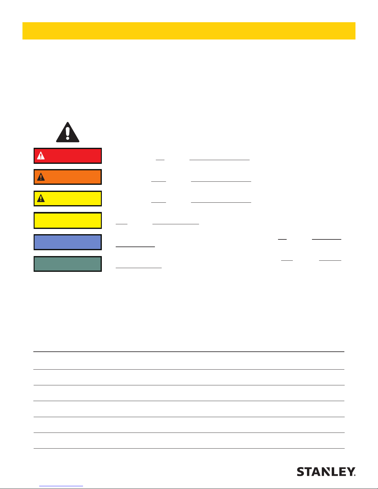
SAFETY SYMBOLS
Safety symbols and signal words, as shown below, are used to emphasize all operator, maintenance and repair actions which, if not strictly followed, could result in a life-threatening situation, bodily injury or damage to equipment.
This is the safety alert symbol. It is used to alert you to potential personal injury
hazards. Obey all safety messages that follow this symbol to avoid possible injury
or death.
This safety alert and signal word indicate an imminently hazardous situation which,
if not avoided, will result in death or serious injury.
This safety alert and signal word indicate a potentially hazardous situation which, if
not avoided, could result in death or serious injury.
This safety alert and signal word indicate a potentially hazardous situation which, if
not avoided, could result in death or serious injury.
This signal word indicates a potentially hazardous situation which, if not avoided,
may result in property damage.
This signal word indicates a situation which, if not avoided, will result in damage to
the equipment.
This signal word indicates a situation which, if not avoided, may result in damage
to the equipment.
Always observe safety symbols. They are included for your safety and for the protection of the tool.
LOCAL SAFETY REGULATIONS
Enter any local safety regulations here. Keep these instructions in an area accessible to the operator and maintenance personnel.
4 ► SRP 2240 / 3860 User Manual
Page 5
FOREWORD
These instructions include:
• Safety regulations
• Operating instructions
• Maintenance instructions
These instructions have been prepared for operation on the
construction site and for the maintenance engineer.
These instructions are intended to simplify operation of
the machine and to avoid malfunctions through improper
operation. Observing the maintenance instructions will
increase the reliability and service life of the machine when
used on the construction site and reduce repair costs and
downtimes.
Always keep these instructions at the place of use of the
machine.
Only operate the machine as instructed and follow these
instructions.
Also observe the corresponding rules and regulations valid
in your country. Always comply with the safety provisions in
your county and state.
Stanley is not liable for the function of the machine when
used in an improper manner and for other than the intended purpose.
Operating errors, improper maintenance and the use of incorrect operating materials are not covered by the warranty.
The above information does not extend the warranty and
liability conditions of business of Stanley.
We reserve us the right to make changes due to technical
development without announcement.
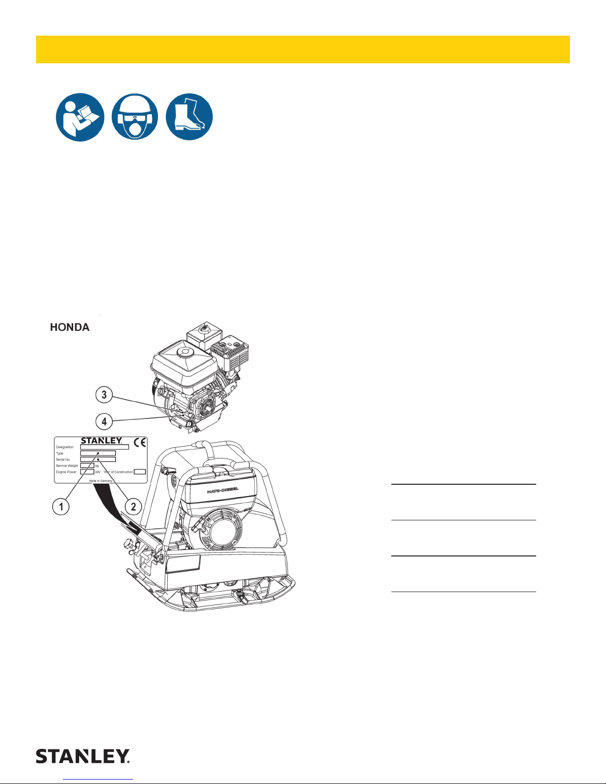
PLEASE ENTER (DATA ON MACHINE TYPE PLATE)
1. MACH.-TYPE:
2. MACH.-NO.:
3. ENGINE-TYPE:
4. ENGINE-NO.:
Stanley Hydraulic Tools
3810 SE Naef Rd
Milwaukie, OR 97267
Ph: 503-659-5660
Fax: 503-652-1780
www.stanleyhydraulics.com
SRP 2240 / 3860 User Manual ◄ 5
Page 6

SAFETY
This Stanley machine has been built according to the state of the
art in compliance with the pertinent rules. Nevertheless, these
machines can still constitute a hazard to persons and property if:
• not used for the intended purpose,
• not operated by suitably qualied and instructed personnel,
• modied or converted in an improper manner,
• the pertinent safety regulations are not observed
For this reason, any person entrusted with the operation, maintenance or repair of the machine is obliged to read and follow the
operating instructions and particularly to observe the safety
regulations. If necessary, it must be conrmed by the signature of
the company using the machine.
Furthermore, the following must be made known and observed:
• pertinent regulations for the prevention of accidents,
• generally recognized safety rules,
• country-specic regulations
Normal use
The machine is suitable for all compaction jobs in civil works and
road construction. All ground materials such as sand, gravel,
sludge, crushed stone, asphalt and composite sett paving can be
compacted.
Improper use
The machine can constitute hazards if not used by instructed
personnell or for other than the intended purpose.
Weighing down and riding on the machine is forbidden.
The machine must not be used on slopes with a gradient of more
than 25° (Honda 20°).
Do not use the machine on hard concrete, set asphaltic surfaces,
highly frozen or unstable surfaces.
Who is allowed to operate the machine?
Only suitable qualied, instructed and authorised persons over 18
years of age may operate the machine.
In variance from this, minors can be employed, as long as it is
necessary to their training objective and their protection is assured
by a supervisor.
Persons under the inuence of alcohol, medication or drugs must
not operate, maintain or repair the machine.
Maintenance and repairs, in particular of hydraulic systems and
electronic components require special knowledge and must be
carried out only by skilled persons (mechanics specialising in
construction and agricultural machinery).
Conversions and modications to the machine
Unauthorized modications and conversion of the machine are not
permitted for safety reasons.
Spare parts and special equipment not delivered by us are also
not approved by us. The installation and/or the use of such parts
can also have a detrimental effect on the operating safety.
The manufacturer disclaims all liability for any damage resulting
from the use of non-original parts or special equipment.
Safety information contained in the operating and maintenance
instructions
The following terms and symbols are used in this operating
manual that draw attention to important information:
Refers to special information and/or orders and
prohibitions directed towards preventing damage
Attention
Refers to orders and prohibitions designed to
prevent injury or extensive damage.
Danger
Refers to special information on how to use the machine
most efciently.
Important
Transporting the machine
Only load and transport the machine as specied in the operating
instructions.
Only use suitable means of transport and hoisting with sufcient
loading capacity!
Attach suitable slinging means to the points of attachment
provided.
Secure the machine to prevent it from tilting or slipping.
It is highly dangerous to walk or stand under suspended loads.
Secure the machine on transport vehicles to prevent it from
rolling, slipping and tilting.
Starting the machine
Prior to starting
Familiarise yourself with the operating and control elements and
the mode of operation of the machine and the working environment. This includes, e.g. obstacles in the working area, loading
capacity of the ground and the necessary safety provisions.
Use personal protective equipment (safety footwear, hearing
protectors, etc.).
Check to ensure that all safety devices are rmly in place.
Do not start the machine if instruments or control devices are
faulty.
Starting
For machines with hand start, only use the safety cranks tested by
the manufacturer, and precisely follow the operating instructions
of the motor manufacturer.
To crank-start diesel motors; Important is the correct position to
the motor and the correct hand position on the crank.
The hand crank must be turned with maximum force until the motor starts, otherwise the crank can rebound.
Precisely follow the starting and stopping procedures specied in
the operating instructions and observe indicator lights.
Only start and operate machines with an electrical starter from the
instrument panel.
Starting and operation of the machine in potentially explosives
atmospheres is forbidden!
Starting with battery junction cables
Connect «positive» to «positive» and «negative» to «negative»
(earthing lead). Always connect the earthing lead last and discon-
nect rst! Incorrect connection will cause serious damage to the
electrical system.
Starting in enclosed spaces, tunnels, mines or deep ditches
Engine exhaust gas are highly dangerous!
For this reason, when operating the machine in enclosed spaces,
tunnels, mines or deep ditches, it is important to ensure that there
is sufcient air to breath (see UVV «Construction work», BGV
C22, paragraphs 40 and 41).
6 ► SRP 2240 / 3860 User Manual
Page 7

SAFETY
Machine control
Operating devices which adjust themselves automatically when
released in normal use, must not be locked.
Check protective devices and brakes for proper functioning prior
to operation.
When reversing, particularly on the edges and banks of ditches,
as well as in front of obstacles, the machine operator cannot fall
or be crushed.
Always keep a safe distance away from the edges and banks
of ditches and refrain from any actions which could cause the
machine to topple over!
Always control the machine, so that hand injuries through hard
objects are avoided!
Always ascend slopes carefully in a direct path.
Reverse up steep slopes to prevent the machine from toppling
over on to the machine operator.
If faults on the safety devices or other faults detrimental to the
safe operation of the machine are noticed, operation of the machine must be stopped immediately and the faults remedied.
When undertaking compaction work in the vicinity of buildings or
above pipelines and similar, check the effect of the vibrations on
the buildings and pipes and stop compaction work if necessary.
Parking the machine
Park the machine on a rm and level surface.
Shutdown the drive and secure it to prevent accidental movement and unauthorized use. If available, close the fuel valve. Do
not place or store equipment with integrated moving gear on the
chassis. The moving device is intended only for transportation
purposes.
Filling Fuel
Only ll fuel by switched-off motor. No open re, do not smoke.
Do not spill any fuel, collect discharging fuel in a suitable
container, prevent fuel from seeping into the soil.
Ensure that the ller cap is tight.
Leaky fuel tanks constitute an explosion hazard and must therefore be replaced immediately.
Maintenance and repairs
Observe the maintenance, inspection and adjustments and intervals specied in the operating instructions, as well as the information for part replacement.
Maintenance work must be undertaken only by qualied and
authorised persons.
Maintenance and repairs only by switched-off drive.
Only carry out maintenance and repairs when the machine is
parked on a rm and even surface and is secured to prevent it
from rolling.
When changing larger assemblies and individual components,
only use suitable and perfectly functioning hoisting and lifting
gears with suitable loading capacity. Attach and secure parts on
hoisting carefully!
Spare parts must comply with the technical requirements of the
manufacturer. Therefore only use original spare parts.
Hydraulic lines must previously be rendered pressureless, before
working on them. Hydraulic oil discharging under pressure can
cause serious injuries.
Work on hydraulic devices must be undertaken only by persons
with a special knowledge of hydraulics and the necessary
experience!
Do not adjust pressure relief valves.
Drain hydraulic oil at operating temperature—caution risk of
scalding!
Collect discharging hydraulic oil and dispose of the same in an
environmentally-friendly manner.
Do not start the motor when hydraulic oil has been drained off.
After completing all work (by pressureless system), inspect all
connections and bolted connections for leaks.
Inspect all hoses and bolted connections for leaks at regular
intervals and externally visible damage! Rectify any damage
immediately.
Replace externally damaged hydraulic hose lines at regular
intervals (depending on time used), even when no safety-relevant
faults are visible.
Before working on the electrical system of the machine,
disconnect the battery and insulate by covering or remove.
Inspect the electrical equipment of the machine at regular intervals. Faults such as loose connections, worn or scorched cables
must be immediately eliminated.
During transport, secure the battery to prevent it from tilting, shortcircuit, slipping and damage.
Dispose of used batteries in a proper manner. Do not place any
tools on the battery.
Handling acid-batteries
Transport lled batteries upright to prevent acid spillage.
Keep away from sparks, open re and other sources of ignition.
Avoid contact of acid with skin and clothing. In case of contact,
wash off acid immediately with clear water and go to medical
institution.
Properly ret and inspect all protective devices after maintenance
and repairs.
Testing
Road rollers, trench rollers and vibrating plates must be tested for
safety by an expert depending on the particular application and
operating conditions as required, however at least once a year.
Disposal of the machine after nish of its service life
At disposal of the machine after nish of its service life, the owner
is obliged to comply with national regulations and laws on wastes
and protection of environment. Therefore we recommend in
such cases to contact the following:
• professional specialized companies engaged in such activities
and having the relevant certicate
• the manufacturers or contracting service organizations authorized by him.
The manufacturer is not responsible for damages to health of
owners neither for damages to the environment in events of failing
to comply with above mentioned hygienic and ecological
principles.
SRP 2240 / 3860 User Manual ◄ 7
Page 8
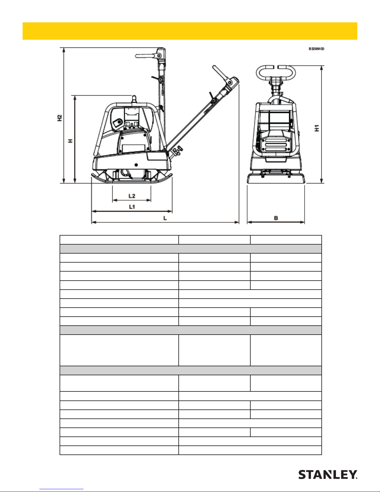
TECHNICAL DATA
SRP 2240 (HONDA) SRP 3860 (HONDA)
1. DIMENSIONS
LENGTH L 1140 MM / 44.8 IN 1365 MM / 53.7 IN
LENGTH L1 600 MM / 23.6 IN 860 MM / 33.8 IN
LENGTH L2 254 MM / 10.0 IN 410 MM / 16.1 IN
HEIGHT H 610 MM / 24.0 IN 750 MM / 29.5 IN
HEIGHT H1 1000 MM / 39.3 IN
HEIGHT H2 1180 MM / 46.4 IN
WORKING WIDTH B1 400 MM / 15.7 IN 450 MM / 17.7 IN
WORKING WIDTH B2 ---- 600 MM / 23.6 IN
2 WEIGHTS
BASIC UNIT B1
BASIC UNIT B2
TRANSPORTATION KIT
ELECTRICAL STARTER
3. DRIVE
MOTOR-TYPE
TYPE OF CONSTRUCTION 1-CYL-4-STROKE GASOLINE
POWER 2.9 KW (4.0 HP) 6,3 KW (8,6 HP)
BY SPEED 3600 1/MIN 3100 1/MIN
COOLING SYSTEM AIR
FUEL CONSUMPTION 0.9 L/H 2,1 L/H
MAX. SLOPING POSITION 20°
MAX. GRADE ABILITY 35 %
100 KG / 220.4 LB
----
+ 8 KG
----
HONDA
GX 120
242 KG / 533.5 LB
257 KG / 566.5 LB
----
----
HONDA
GX 270
8 ► SRP 2240 / 3860 User Manual
Page 9
TECHNICAL DATA
SRP 2240 SRP 3860
DRIVE VIA CENTRIFUGAL CLUTCH AND V-BELT
SHIFT (FORWARD / REVERSE) HYDRAULIC
4. SPEED
BASIC UNIT B1 0-25 M/MIN 0-26 M/MIN
BASIC UNIT B2 ---- 0-26 M/MIN
5. VIBRATION
CENTRIFUGAL FORCE 22 KN 38 KN
VIBRATION FREQUENCY 98 HZ 65 HZ
6. MAXIMUM PERFORMANCE
BASIC UNIT B1 600 m²/h 700 m²/h
BASIC UNIT B2 936 m²/h
7. FILLING QUANTITIES
2.5 l 6.0 l
8. OPTIONAL EQUIPMENT
VULKOLLAN MAT 16 IN.
VULKOLLAN MAT 24 IN.
P/N-75185
---
---
P/N-75264
TRANSPORTATION WHEELS
O = Option / S = Serial / — = Not available
9. NOISE AND VIBRATION DATA
THE FOLLOWING NOISE AND VIBRATION DATA ACCORDING TO EC MACHINERY DIRECTIVE
IN THE VERSION (2006/42/EC), WAS DETERMINED, TAKING INTO ACCOUNT THE FOLLOWING
STANDARDS AND DIRECTIVES. IN OPERATIONAL USE, VALUES CAN DEVIATE DEPENDING ON
THE PREVAILING CONDITIONS.
9.1 NOISE DATA
THE NOISE DATA SPECIFIED IN APPENDIX 1, SUB-CLAUSE 1.7.4.U OF THE EC MACHINERY
DIRECTIVE IS FOR:
SOUND PRESSURE LEVEL AT THE
OPERATOR PLACE LPA
MEASURED SOUND POWER LEVEL
LWA,M
GUARANTED SOUND POWER LEVEL
LWA,G
THE NOISE VALUES WERE DETERMINED, TAKING INTO ACCOUNT THE FOLLOWING DIRECTIVES AND STANDARDS: DIRECTIVE 2000/14/EC / EN ISO 3744 / EN 500-4
9.2 VIBRATION DATA
HAND/ARM VIBRATION VALUES ACCORDING TO APPENDIX 1, SUB-CLAUSE 3.6.3.1 OF THE EC
MACHINERY DIRECTIVE:
TOTAL VIBRATION VALUE OF THE
ACCELERATION AHV
UNCERTAINTY K 0.5 m/s²
THE ACCELERATION VALUE WAS DETERMINED, TAKING INTO ACCOUNT THE FOLLOWING
DIRECTIVES AND STANDARDS: EN 500-4 / DIN EN ISO 5349
P/N-75885
97.3 dB 103.7 dB
104 dB 105 dB
105 dB 108 dB
4.3 m/s² 2.0 m/s²
---
1) AS THE PERMISSIBLE RATING SOUND LEVEL OF 85 DB (A) CAN BE EXCEEDED BY THIS MACHINE, OPERATORS
MUST WEAR HEARING PROTECTORS.
SRP 2240 / 3860 User Manual ◄ 9
Page 10

OPERATION
Description
The SRP 2240/3860 is a reversible vibrating plate operating on the basis of the twin-shaft vibration system principle. The engine drives the exciter on the baseplate via
a centrifugal clutch and a V-belt. The exciter produces the
vibration required for compaction as a result of the built-in
imbalance.
The machine is guided at the tow-bar grip. It is operated
with the operating controls on the tow-bar.
The SRP 2240/3860 is suitable for all compaction work in
the elds of civil engineering and road construction. It can
be used to compact all ground materials such as sand,
gravel, slag, crushed stone, asphalt and composite sett
paving.
Take great care on downslopes. The machine
Danger
could slip down due to loose material or if the
surface is slippery.
Do not use the machine on hard concrete, set
asphaltic surfaces, highly frozen or unstable
surfaces.
2
Operating control at the tow-bar
1 Control lever
The control lever serves for adjustment of the unbalances
in the exciter and in turn for coninuous regulation.
I Forward
0 Point compacting
II Reverse
The control lever remains automatically in position only
when set to the maximum forward travel setting (a). In any
other position, the control lever moves in the direction of
maximum forward travel when released.
If the control lever is operated too quickly several times, the
shift lever will block in reverse travel. In this case:
• Release lever in forward travel position up to maximum
forward travel position
• Blocking is cleared within a few seconds and perfect
shifting is possible.
1 Engine
2 Central point suspension
3 Tow-bar
4 Operating control/tow-bar
5 Base plate with exciter
6 Transport truck (Special equipment)
10 ► SRP 2240 / 3860 User Manual
The control lever can be operated only with the engine
running. The lever blocks if operated when the machine is
stationary. Blocking is immediately cleared when the engine
is restarted.
2 Engine speed control lever
STOP Engine stop (SRP 3860 only)
MIN Idle (detent position)
MAX Full load.
The motor speed can be adjusted steplessly with the control lever. At minimum motor speed (min), the drive to the
exciter is disconnected at the centrifugal clutch and the motor idles. The centrifugal clutch engages when the control
lever is moved approximately ¼ of its adjustment travel.
Page 11

OPERATION
Before Operation
Use personal protective equipment (in particular
Danger
• Stand the machine on an even surface.
• Check
- the Engine oil level
- the hydraulic oil level
- the fuel supply
- that screw connections are secure
- condition and function of hydraulic hose lines
- the condition of the Engine and the machine.
• Top-off any missing lubrication in accordance with the
lubrication table.
hearing protectors and safety shoes). Risk of loss
of hearing!
Observe the safety conditions.
Observe the operation and maintenance
instructions.
Read the Engine operating instructions. Observe
the Importants on safety, operation and maintenance contained in them.
Adjusting / Locking the tow-bar
Adjusting the tow-bar
By turning adjustment-screw (2), the tow-bar (1) can be set
to any positions so as to obtain the best working height on
the tow-bar grip.
Locking the tow-bar
In case of loading and transport the tow-bar (1) has to be
locked in an upright position by turning up the locking bolt
(3).
SRP 2240 / 3860 User Manual ◄ 11
Page 12

OPERATION
Engine Operation - Honda
Starting the engine
• Move the fuel valve lever (2) to the «ON» position.
• Turn the engine switch (4) to the «ON» position.
• Move the choke lever (3) to the «CLOSE» position.
• Set the engine speed lever (1) to MIN.
If the motor doesn't start, set the throttle lever
Important
12 ► SRP 2240 / 3860 User Manual
about 1/3 of the way to «MAX».
• Pull the starter grip (5) lightly until you feel resistance,
then pull briskly in the direction of the arrow as shown
above.
• Return the starter grip gently.
Do not allow the starter grip (5) to snap back
Important
against the engine. Return it gently to prevent
damage to the starter.
Page 13

OPERATION
Warm up Instructions
• Set the engine speed lever (1) to idle (MIN).
• Allow the engine to run for 1-2 minutes in order to
warm up.
Stopping the engine
To stop the engine in an emergency, simply
Important
• Set the engine speed lever (1) to the «MIN» position.
turn the engine switch to the «OFF» position.
• If the choke lever (3) has been moved to the «CLOSED»
position to start the engine, gradually move it to the
«OPEN» position as the engine warms up.
• Turn the engine switch (4) to the «OFF» position.
• Turn the fuel valve lever (2) to the «OFF» position.
SRP 2240 / 3860 User Manual ◄ 13
Page 14

OPERATION / TRANSPORT
Operation
• Set the engine speed lever (2) to full load (MAX).
Operate the machine only at full throttle and turn
the machine in the idle position. Otherwise could
Attention
cause clutch damage or slipping of centrifugal
clutch.
Loading and Transportation
Only use sufciently strong and secure loading
Danger
ramps when loading.
Check the contact points (frame, lifting rings)
before use for damage and wear. Immediately replace damaged parts.
Secure the machine against rolling or slipping off
and against tipping over.
Ensure that no persons will be endangered.
When loading, lashing down and lifting the
machine always use the provided lifting points.
Persons are in danger, if they :
• go near swinging loads or
• stand under swinging loads
Lock the tow-bar to loading and transport.
• The proper position for the operator is behind the machine.
• Control and steer the machine using the tow bar grip (1).
• Set the travel direction and speed with the travel lever (2).
For compaction of paving stones, it is recom-
Important
mended to use Vulkollan plates and protective brackets (special accessories) to prevent
damages to the compaction material and to the
machine.
14 ► SRP 2240 / 3860 User Manual
After loading the machine should be lashed in place.
Use the centre-of-gravity suspension point (2) in order to lift
the machine.
Page 15

TRANSPORT
Transportation Trolley
During longer work breaks, e.g. at the end of the
work day, do not place the machine on the trans-
Danger
The transport trolley can be used for problem-free transport
of the machine.
port trolley so that the stability of the machine is
not compromised.
Take care when riding over uneven or sloping
oors. The machine can slip or tip over.
• Position the towing bar (1) vertically.
• Position the towing bar (1) horizontally and lock in
position (4).
• Remove the undercarriage (2) from the mounting bracket
(3) and place it on the oor.
• With the towing bar locked in position tip the machine on
to the front edge, the undercarriage will swing under the
board.
Be careful when raising and lowering the machine.
Danger
Do not place your feet under the raised base plate.
Danger of foot injuries!
SRP 2240 / 3860 User Manual ◄ 15
Page 16

TRANSPORT
• Using the towing bar, tilt the machine backwards until the
machine is horizontally seated on the undercarriage. The
device is ready to be moved.
• After transport hook the undercarriage back into position
by proceeding in reverse order.
1)Special equipment
16 ► SRP 2240 / 3860 User Manual
Page 17

MAINTENANCE
General Information
Maintenance:
increased service life
increased function
reduced downtimes
increased reliability
reduced repair costs
– Observe the safety regulations!
– Maintenance work should only be carried out when
the engine is shut off.
– The engine and machine should be cleaned thorougly
before carrying out maintenance work.
– Park the machine on a at surface and secure it against
rolling away and slipping.
– Ensure that operating materials and replaced parts are
disposed of safely and in an environmentally-friendly
way.
Maintenance Schedule
MaintenanceWorks
Clean machine
Check engine oil level 1)
Change engine oil 1)
Check the water trap 1)
Clean engine oil lter 1)
Clean fuel lter 1)
Change fuel lter 1)
Check air lter 1)
Change air lter element 1)
Check valve clearance 1)
Exciter: Check oil level
Exciter: Change oil ²)
Check rubber buffers
Check hydraulic oil level
Change hydraulic oil
Check the hydraulic hose lines ²)
Check V-belt
Check screwed connections for
tightness
1
)See engine operating manual
2
)or annually
3
)for the rst time
Intervals
Daily 20 h 50 h 100 h 200 h 250 h 400 h
•
•
3
•
) •
•
3
•
)
•
3
•
) •
3
•
) •
– Before commencing work on any electrical equipment,
disconnect the battery and cover it with insulating materials.
– Do not exchange «PLUS» and «MINUS» poles on the
battery.
– It is essential that short-circuits be prevented in cables
carrying current.
– Before welding work on the machine disconnect all battery connections and cables.
– Burn-out lightbulbs in indicator lamps should be
replaced immediately.
– When cleaning the machine with a high-pressure water
jet, do not spray the electrical components directly.
– After cleaning the components, blow-dry them with compressed air in order to prevent surface corrosion.
If
Necessary
•
•
•
•
3
•
) •
•
•
•
SRP 2240 / 3860 User Manual ◄ 17
Page 18

Lubrication Schedule
MAINTENANCE
Lubricating point Quantity
1. Engine
SRP 2240 0.6 l
SRP 3860 1.1 l
2. Exciter
SRP 2240 0.5 l
SRP 3860 1.0 l
2. Hydraulic
SRP 2240 0.17 l
SRP 3860 0.65 l
Changing intervals
[operating hours]
First time after 20 h;
then every 100 h
First time after 100 h
the every 500 h or
annually
Not Necessary
Lubricant
Engine oil
API SG-CE
SAE 10W40
Engine oil
API SG-CE
SAE 10W40
Hydro-Oil
HVLP 46
Alternative Lubrication Schedule
18 ► SRP 2240 / 3860 User Manual
Page 19

MAINTENANCE
Maintenance Work (Honda)
Only the maintenance work which has to be performed
daily is included in the Operating Manual. Please refer
to the engine Operating Manual and to the maintenance
instructions and intervals listed therein.
Filling-up with fuel
Only add fuel when engine is off and has
cooled down.
Danger
No open ame. Do not smoke.
Do not ll-up in closed rooms. Do not inhale
petrol fumes.
Collect spilt fuel in a suitable container and
prevent spillage entering the soil.
SRP
SRP
Checking the engine oil level
Immediately replace damaged seals.
Collect old oil and dispose of it in an environment friendly manner.
Environment
Do not permit oil to run onto the oor into
the drains.
– Stand the machine horizontally.
– Stop the engine.
– Stop the engine.
– Clean around the fuel ller socket.
– Open the fuel ller socket and visually check the fuel
level. Rell the tank if the fuel level is low.
Never use stale or contaminated gasoline or an
Important
oil/gasoline mixture. Avoid getting dirt or water
in the fuel tank.
– Add fuel to the bottom of the maximum fuel level limit of
the fuel tank. Do not overll. Use unleaded automotive
gasoline only.
– Wipe up spilled fuel before starting the engine.
– Close the tank tightly.
– Remove the oil ller cap/dipstick (1) and wipe it clean.
– Insert the oil ller cap/dipstick (1) into the oil ller neck as
shown, but do not screw it in, then remove it to check the
oil level.
– If the oil level is near or below the lower limitmark on the
dip- stick, ll with the recommended oil to the upper limit
mark (bottom edge of the oil ll hole). Do not overll.
– Reinstall the oil ller cap/dipstick (1).
SRP 2240 / 3860 User Manual ◄ 19
Page 20

MAINTENANCE
Clean the air lter
Change the lter element:
Attention
– if the lter element is damaged
– if moist or oily deposits are present
– if engine performance reduces
– minimum once a year
Never operate the engine without air lter. Do
not allow dust to enter into carburator.
– Paper air lter element:
- Blow compressed air [not exceeding 207 kPa (2.1 kgf/
cm,30 psi)] through the lter element (4) from the inside.
– Foam air lter element (5):
- Clean in warm soapy water, rinse, and allow to dry thor-
oughly. Or clean in non-ammable solvent and allow to
dry.
- Dip the lter element (5) in clean engine oil, then
squeeze out all excess oil. The engine will smoke when
started if too much oil is left in the foam.
– Wipe dirt from the inside of the air cleaner case and
cover using a moist rag. Be careful to prevent dirt from
entering the air duct that leads to the carburetor.
– Place the foam air lter element (5) over the paper ele
ment (4).
– Reinstall the assembled air lter. Be sure the gasket is in
place beneath the air lter.
– Tighten the air lter wing nut securely.
– Install the air cleaner cover (2), and tighten the wing nut
securely.
– Remove the wing nut (1) from the air cleaner cover (2),
and remove the cover.
– Remove the wing nut from the air lter (3), and remove
the lter.
– Remove the foamlter (5) from the paper lter (4).
– Inspect both air lter elements, and replace them if they
are damaged. Clean the air lter elements if they are to
be reused:
Never use petrol or cleaning solutions with a
low ash point for cleaning the lter element!
Danger
Do not smoke in the working area; avoid
open re and sparks – re and explosion
hazard!
Risk of eye injuries! – Wear safety goggles.
20 ► SRP 2240 / 3860 User Manual
Page 21

MAINTENANCE
Maintenance work - Machine
Cleaning
Clean the machine thoroughly daily.
For cleaning, do not use any ammable or
Attention
aggressive materials.
When cleaning the machine with a pressure
washer, do not spray the electrical components
directly.
When cleaning the machine with a pressure
washer, do not hold it directly over the air lter.
Tightening Torque
Torque Information
• Clean the machine on a daily basis.
• After cleaning all cables, hoses and connections check
the unit for leakage on hoses or at connections. Check for
chang points and other damage.
Do not use your hand to check hoses for leaks as this
could cause pressurized oil injection into body.
• Detected faults are to be eliminated immediately.
Strength grades for screws with untreated, unlubricated
surfaces.
The values show 90% use of the yield strength; at a friction
coef- cient of µtot = 0.14.
Tightening torque is controlled with torque wrenches.
The values given do not apply when MoS2 lubrication is
used.
Replace all self-locking nuts after each
Important
disassembly.
SRP 2240 / 3860 User Manual ◄ 21
Page 22

MAINTENANCE
Screw Connections
With vibrating devices, it is important to check intermittently
the screw connections for tightness. Pay attention to the
tightening torque.
Checking the rubber buffers
Check the rubber buffers (1) for tears and outbreaks, as
well as for secure t. If they are damaged, replace them
immediately.
22 ► SRP 2240 / 3860 User Manual
Page 23

MAINTENANCE
V-Belt: Tension / Condition - SRP 2240 V-Belt: Tension / Condition - SRP 3860
• Remove V-belt guard.
• Check V-belt for tension and condition.
• Tension if necessary:
SRP
• Unscrew the nuts (1) of the rubber stops on the outside.
• Push the upper tray (2) upwards on both sides.
It is important to ensure that the frame is also
actually pushed on the rubber stop contact
Important
surfaces and not just the rubber elements are
stretched and then spring back again. If necessary apply light blows with a hammer to knock
the rubber stops downwards.
• Remove V-belt guard.
• Check V-belt for tension and condition.
• Tension if necessary:
SRP 3860
• Loosen set screws (1), do not unscrew.
• Insert auxiliary tools (ø 6 mm) into bores (2) and (3).
• Tension vee-belt by turning clutch halves (2) and (3) in
opposite directions
• Tension clutch halves (2) and (3). X= 10 mm.
• Crank the drive manually and re-check tension and
correct if necessary.
• Replace V-belt guard.
• Both buffers should be equally pre-tensioned.
• Tighten nuts (1).
• Crank the drive manually and re-check tension and
correct if necessary.
• Replace V-belt guard.
Do not start the engine without V-belt
Danger
guard. Danger of injuries.
• Check the tension of the V-belt after 25 op. hrs. again.
Adjust the tension if necessary.
Do not start the engine without V-belt
guard. Danger of injuries.
Danger
• Check the tension of the V-belt after 25 op. hrs. again.
Adjust the tension if necessary.
SRP 2240 / 3860 User Manual ◄ 23
Page 24

MAINTENANCE
Exciter: Oil Level / Oil Change
Check / change exciter oil when its warm.
SRP 3860: The venting screw (3) must always
Important
rst be unscrewed when checking the oil level
or changing the oil.
• Unscrew venting screw (3), oil lling plug/dipstick (1) and
oil drain plug (2).
• Drain-off old oil.
• Fill-in new oil through the oil ll hole (1). See lubrication
plan for quantity and quality.
When the dipstick is screwed in, the optimal
oil level is between the «MIN» and «MAX»
Attention
markings.
• Replace oil lling plug/dipstick (1) and venting screw (3).
• Unscrew oil lling plug/dipstick (1), check the oil level
again and top up with oil if necessary.
Care is to be taken with the draining of
Danger
hot oil: Danger of scalding!
Collect oil which has run out or over-
owed and dispose it in an environment
Environment
friendly manner.
• Screw-in oil drain screw (2).
24 ► SRP 2240 / 3860 User Manual
Page 25

MAINTENANCE
Filling and Bleeding the Circuit Hydraulic Hose Lines
SRP
SRP 3860
• Release locking screw (1).
• Set throttle lever (2) to «V».
• Pour in hydraulic uid while continually changing the
throttle lever position. To ensure correct bleeding, at
times place the shaft vertically.
• Stop lling when
- a distinct «clicking»-noise is heard in the exciter
while shifting the lever
- you will no longer feel a cushion of air when
moving the throttle lever.
1 Serial No.
2 Manufacturer/Month and year of manufacture
3 Max. operating pressure
The function of hydraulic hose lines must be tested at
regular intervals (minimum once a year) by an expert (with
a knowledge of hydraulics).
Hose lines must immediately be replaced in the following
instances:
• Damage to the outer layer to the inner lining (abrasion
marks, cracks, cuts, etc.).
• Brittleness of the outer layer (cracking of hose covering).
• Unnatural deformations of the hose line. This applies to
both a pressureless and pressurised condition (e.g. layer
separation, blister formation, crushed areas, kinks).
• Leaks.
• Damage or deformation of hose ttings (impaired sealing
function).
• Hose slips out of the tting.
• Corrosion of tting (degrading of function and strength).
• Improper installation.
• Use beyond the expiry date of max. 6 years.
When lling, the circuit path is shortened.
Important
• To check oil level, start engine and bring up to operating
speed.
• Move throttle lever several times backwards and for
wards between «V» and «R».
• The correct oil level should be somewhere in the area
shown (See Illus.); at this point the throttle lever must be
in the «V» position.
• If the level is too low, top up with hydraulic uid; if too
high, drain off excess uid.
• With the machine running and the throttle lever in the
«V» position, close locking screw (1).
SRP 2240 / 3860 User Manual ◄ 25
Page 26

TROUBLESHOOTING
General Information
• Observe the safety information
• Only qualied and authorised persons may carry out
repair work (mechanics specialising in construction and
agricultural machinery).
• In case of faults, the operating and maintenance instruc tions must be referred to for correct operation and main tenance.
Fault Table
Possible cause Remedy Remarks
Engine does not start
Speed control lever in «STOP»-position
No fuel
– Tank run dry
– Fuel lter blocked
– Fuel valve «OFF»
– Defective feed pump
Oil pressure lost
Compression too low
Set lever to «START»-position
Add fuel
Renew fuel lter
Move lever to «ON» position
Function must be checked
Check engine oil level
Contact a Stanley-service center
• If the cause of the fault cannot be located or remedied, an
authorised Stanley Service Center should be contacted.
• Always rst check the most likely causes (fuses,
LEDs, etc.).
HONDA
Engine switch «OFF»
Choke «OPEN»
Spark plug faulty, fouled or improperly
gapped
Spark plug wet with fuel (ooded engine)
Turn engine switch to «ON» position
Move lever to «CLOSE» position
Gap or replace spark plug
Dry and reinstall spark plug
Engine stops by itself during regular operation
Fuel supply is interrupted
– Tank run dry
– Fuel lter blocked
– Defective feed pump
Oil pressure lost
Mechanical defects
Add fuel
Renew fuel lter
Function must be checked
Check engine oil level
Contact a Stanley-service center
Reduced engine performance
Fuel supply is obstructed
– Tank run dry
– Fuel lter blocked
– Tank venting is inadequate
– Leaks at pipes unions
Air cleaner blocked
Incorrect valve clearance
Too much oil in engine
Too much oil in exciter
Default in hydraulic system
Add fuel
Renew fuel lter
Ensure that tank is adequately vented
Check threaded pipe unions
Remove dirt from air cleaner
Adjust valve clearance
Correct the engine oil level
Check exciter oil level
Contact a Stanley-service center
Engine runs, machine does not move forward
Insufcient V-belt tension
V-belt broken
Centrifugal clutch lining worn
Too much oil in exciter
Default in hydraulic system
Retention V-belt
Replace V-belt
Replace linings and springs
Check exciter oil level
Contact a Stanley-service center
HONDA
HONDA (Unless the engine is warm)
HONDA
HONDA (Start engine with throttle
lever in «MAX» position)
26 ► SRP 2240 / 3860 User Manual
Page 27

NOTES
SFP 2240 / 3860 User Manual ◄ 27
Page 28

Stanley Hydraulic Tools
3810 SE Naef Road
Milwaukie, Oregon 97267-5698 USA
(503) 659-5660 / Fax (503) 652-1780
www.stanleyhydraulics.com
 Loading...